
NewsNEWCENTER
Featured products
Contact Us
Schneider 140ACI03000 Analog Input Module Troubleshooting Guide
2026-09-18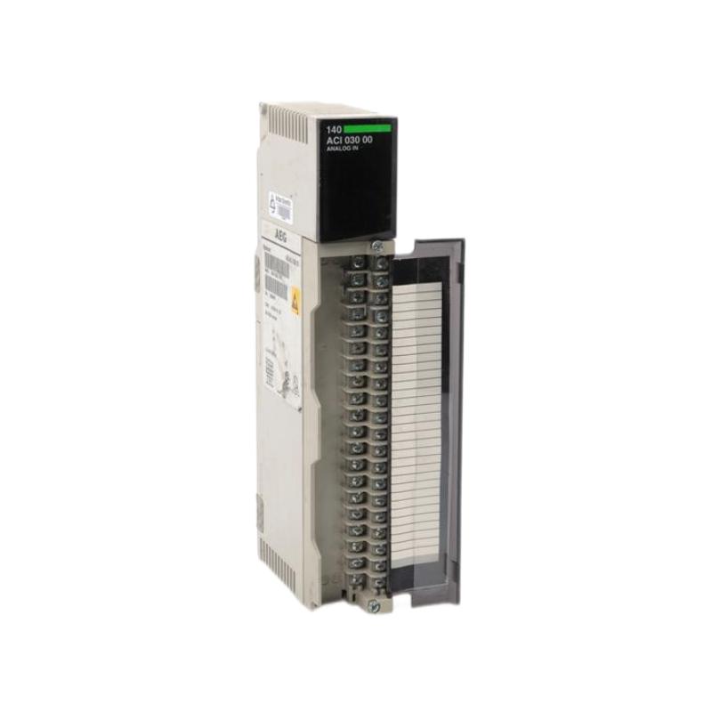
Schneider 140ACI03000 troubleshooting should begin by separating an actual analog input module fault from problems caused by field instruments, wiring, shielding, grounding, configuration, or PLC scaling. Symptoms such as unstable readings, incorrect values, missing channels, or intermittent process signals do not automatically indicate module failure. This Schneider 140ACI03000 Troubleshooting Guide provides a structured method for fault diagnosis, testing, and repair.
Table of Contents
- Schneider 140ACI03000 Fault Diagnosis Overview
- Schneider 140ACI03000 Common Fault Symptoms
- Common Causes of Schneider 140ACI03000 Faults
- Schneider 140ACI03000 Troubleshooting Diagnostic Logic
- Schneider 140ACI03000 Signal Testing and Fault Analysis
- Schneider 140ACI03000 Repair and Replacement Procedure
- Schneider 140ACI03000 Field Troubleshooting Case
- Schneider 140ACI03000 Troubleshooting FAQ
- Schneider 140ACI03000 Technical Summary
Schneider 140ACI03000 Analog Input Module Fault Diagnosis Overview
The 140ACI03000 receives analog information from field devices and transfers that information into the PLC control system. Because the module is one part of a larger measurement chain, troubleshooting should examine the source instrument, field wiring, terminal connections, module channel, PLC configuration, and displayed engineering value.
A useful diagnostic strategy is to find the point where the signal changes from normal to abnormal.
Field Instrument
      |
      v
Field Cable
      |
      v
Terminal Interface
      |
      v
Schneider 140ACI03000
      |
      v
Quantum I/O / Backplane
      |
      v
PLC Data
      |
      v
HMI / SCADA
If the transmitter output is correct but the PLC value is wrong, the investigation can progressively move through the signal path instead of replacing the module immediately.
Schneider 140ACI03000 Common Fault Symptoms
Common symptoms that may lead to an investigation of the 140ACI03000 include:
- Analog value remains fixed.
- Input value fluctuates unexpectedly.
- PLC displays an incorrect engineering value.
- One input channel is unavailable.
- Several related analog signals become abnormal.
- Input values change when nearby motors or drives operate.
- An I/O diagnostic appears after maintenance.
- PLC and local instrument readings do not agree.
- An analog channel behaves intermittently.
Each symptom should be correlated with the operating condition. For example, a value that becomes unstable only when a motor starts may point toward signal interference rather than an internal module defect.
Common Causes of Schneider 140ACI03000 Faults
Field Instrument Failure
A transmitter or analog sensor may produce an incorrect or unstable output. The instrument should be checked independently whenever possible.
Loose or Damaged Wiring
Loose terminals, broken conductors, damaged insulation, or poor connections can cause intermittent analog readings or complete loss of a channel.
Incorrect Configuration
If the physical signal type and PLC configuration do not match, the resulting value may be incorrect even though the electrical connection is intact.
Incorrect Scaling
A valid raw input can be converted into an incorrect engineering value when the application uses an incorrect scaling formula, range, or channel assignment.
Electrical Interference
Drives, motors, contactors, and switching equipment can introduce noise into poorly routed analog cables. Shielding and grounding arrangements should therefore be investigated when fluctuations correlate with equipment switching.
Module Hardware Failure
If the field signal, wiring, configuration, and receiving system are verified while one channel remains abnormal, the 140ACI03000 hardware becomes a stronger candidate for replacement or technical evaluation.
Schneider 140ACI03000 Troubleshooting Diagnostic Logic
Analog Input Fault
       |
       v
Check PLC Diagnostic Information
       |
       v
Verify Field Instrument
       |
   +---+---+
   |       |
 Normal  Abnormal
   |       |
   v       v
Check     Repair /
Wiring    Test Instrument
   |
   v
Check Terminal Connections
   |
   v
Check 140ACI03000 Channel
   |
   v
Check PLC Configuration
   |
   v
Check Scaling
   |
   v
Confirm Root Cause
This sequence is especially useful when a field instrument appears normal but the PLC value is incorrect. It also helps distinguish an electrical signal problem from an application-level scaling problem.
Schneider 140ACI03000 Signal Testing and Fault Analysis
Testing should be performed using instruments appropriate for the actual signal type and plant safety requirements. Critical process loops should be tested according to the approved maintenance and control-loop procedures.
Recommended Test Sequence
- Record the exact abnormal channel and displayed value.
- Determine whether the fault is constant or intermittent.
- Check PLC and I/O diagnostic information.
- Verify the field instrument output.
- Inspect field wiring and terminals.
- Check cable shielding and grounding.
- Compare the physical input with the PLC raw value.
- Check channel configuration.
- Verify engineering-unit scaling.
- Repeat the test while the process changes.
Illustrative Diagnostic Record
Process condition: Stable

Field instrument:
Output behavior = stable

PLC observation:
Analog value = fluctuating

Additional observation:
Fluctuation occurs when nearby switching equipment operates

Diagnostic direction:
Inspect analog cable routing, shielding, grounding,
and electrical interference before replacing the module.
The record above is an illustrative field troubleshooting example, not a universal electrical test specification for the 140ACI03000.
Schneider 140ACI03000 Repair and Replacement Procedure
When evidence points toward a hardware problem, replacement should be performed only after the external signal path has been checked.
Step 1: Document the Fault
Record the affected channel, process condition, PLC value, diagnostic information, and field-instrument behavior.
Step 2: Isolate the System
Follow the plant’s approved isolation procedure before removing the module or disconnecting field wiring.
Step 3: Inspect the Module and Rack
Check the module, rack connector, adjacent wiring, and cabinet for visible damage, contamination, overheating, or loose connections.
Step 4: Verify Field Wiring
Confirm the affected conductor, terminal, polarity where applicable, shielding, and cable continuity using the appropriate procedure.
Step 5: Verify Configuration
Check rack position, module identification, channel assignment, signal configuration, and scaling before concluding that the hardware has failed.
Step 6: Replace the Module if Evidence Supports It
When the external signal path and configuration are confirmed healthy and the channel remains abnormal, replace the module with a properly verified compatible unit.
Step 7: Recommission the Complete Loop
After replacement, verify the field signal, PLC value, engineering scaling, alarm functions, HMI display, and process response.
Schneider 140ACI03000 Field Troubleshooting Case
During a representative process-control maintenance event, one analog process measurement began fluctuating during periods of heavy equipment operation. Operators initially suspected the 140ACI03000 because the unstable value appeared directly in the PLC and HMI.
The maintenance team compared the field transmitter with the PLC indication. The transmitter remained stable while the PLC value changed whenever a nearby motor-driven system started.
The engineers then inspected the signal cable and found that the analog cable was routed too close to a high-power switching path. After improving the cable separation and checking the shielding arrangement, the analog value became stable.
The terminal board and analog input module were therefore not the root cause. This case demonstrates why signal-quality problems should be investigated at the field and wiring level before replacing PLC hardware.
Schneider 140ACI03000 Troubleshooting FAQ
What is the first step when a 140ACI03000 analog value is wrong?
Determine whether the field instrument is producing the correct signal. Then trace the signal through the field wiring, terminal connection, module channel, PLC configuration, and scaling.
Why does the PLC value sometimes fluctuate even though the transmitter is stable?
Possible causes include electrical interference, inadequate shielding, grounding problems, cable routing, loose terminals, or an issue within the I/O signal path.
How can I tell whether the problem is scaling rather than hardware?
Compare the physical signal and the PLC raw input value with the expected configuration. If the raw input follows the field signal but the displayed engineering value is incorrect, the application scaling or channel configuration should be investigated.
Should I replace the 140ACI03000 when one channel stops working?
Not automatically. First check the field instrument, wiring, terminals, configuration, and I/O diagnostics. If those areas are verified and the channel remains abnormal, module replacement may then be appropriate.
What should be tested after replacing the module?
Verify all affected channels, field measurements, PLC values, engineering scaling, alarms, HMI or SCADA indications, and the original operating condition that caused the fault.
Schneider 140ACI03000 Technical Summary
The Schneider 140ACI03000 Analog Input Module forms part of the analog measurement path in a PLC-based industrial control system. Its troubleshooting requires a complete view of field instrumentation, wiring, shielding, grounding, I/O hardware, PLC configuration, and application scaling.
The most reliable troubleshooting method is to trace the analog signal from the field instrument toward the PLC, compare the signal at each stage, and reproduce the original operating condition after corrective work. This approach can distinguish genuine module failures from wiring, configuration, scaling, and electrical-noise problems and can reduce unnecessary hardware replacement.