
NewsNEWCENTER
Featured products
Contact Us
Schneider 140ACI03000 Analog Input Module Installation Guide
2026-09-18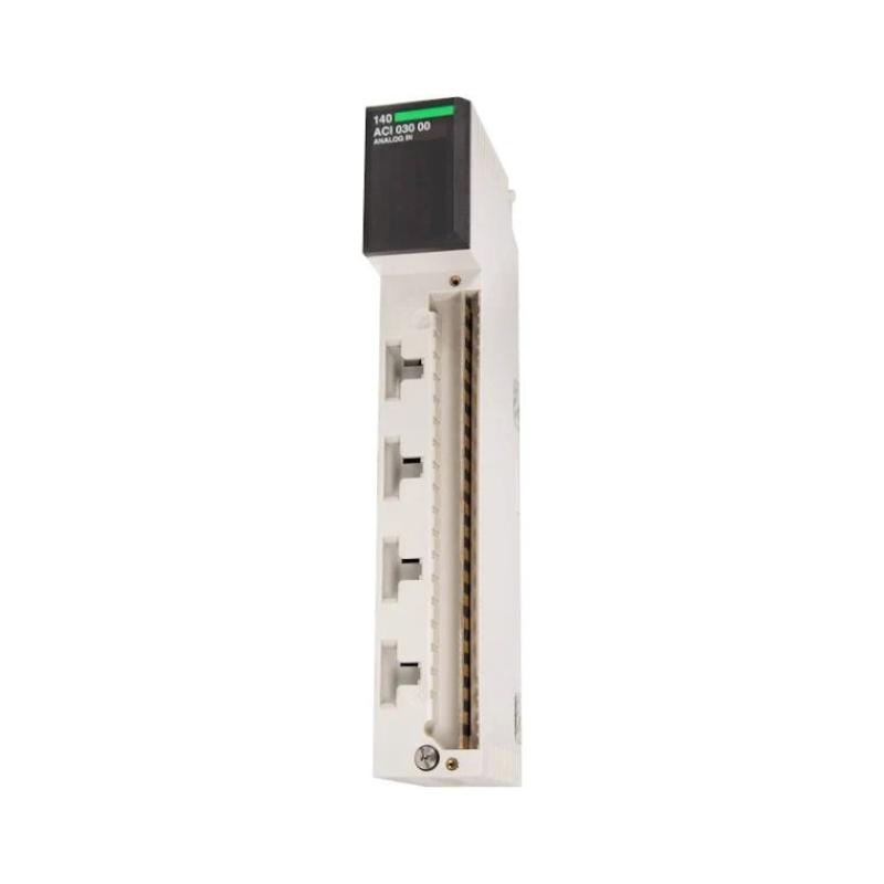
The Schneider 140ACI03000 Analog Input Module installation should be handled as a complete Modicon Quantum I/O integration task, including module identification, rack installation, field wiring, signal configuration, grounding, and commissioning. Correct setup is essential for reliable acquisition of process signals such as transmitters, instrumentation outputs, and other analog devices. This Schneider 140ACI03000 Installation Guide provides a practical workflow for installation, wiring, setup, and commissioning.
Table of Contents
- Schneider 140ACI03000 Analog Input Module Installation Overview
- Schneider 140ACI03000 Function in a PLC Control System
- Schneider 140ACI03000 Installation Preparation
- Schneider 140ACI03000 Rack Installation and Cabinet Layout
- Schneider 140ACI03000 Wiring and Analog Signal Integration
- Schneider 140ACI03000 Setup and Configuration
- Schneider 140ACI03000 Commissioning Procedure
- Schneider 140ACI03000 Installation Validation
- Schneider 140ACI03000 Field Commissioning Case
- Schneider 140ACI03000 Installation FAQ
- Schneider 140ACI03000 Technical Summary
Schneider 140ACI03000 Analog Input Module Installation Overview
The 140ACI03000 is a Schneider Electric analog input module associated with the Modicon Quantum automation platform. Its role is to bring analog process information into the PLC control architecture so that the controller can monitor continuously varying process conditions.
Typical applications can include process transmitters, instrumentation signals, temperature-related conditioning equipment, pressure measurement, flow measurement, level monitoring, and other analog process variables. The exact input type, channel arrangement, scaling, and wiring method must be verified against the applicable module documentation and project drawings.
During installation, the objective is not simply to make the module appear in the PLC rack. The complete signal chain must be correct:
Process Instrument
       |
       v
Field Wiring
       |
       v
Schneider 140ACI03000
Analog Input Module
       |
       v
Quantum I/O Rack
       |
       v
PLC Controller
       |
       v
Control Logic / HMI / SCADA
Schneider 140ACI03000 Function in a PLC Control System
An analog input module converts field-level analog information into data that can be processed by the PLC application. The controller can then use this information for monitoring, alarms, closed-loop control, sequencing, trending, and operator displays.
For example, a process transmitter may continuously change its output according to pressure or flow. The 140ACI03000 receives the corresponding analog signal, processes it through the I/O system, and makes the resulting input value available to the control program.
Typical Application Structure
- Field transmitter or analog instrument
- Signal cable and terminal interface
- 140ACI03000 analog input module
- Quantum rack and backplane
- PLC processor
- HMI or SCADA system
- Control, alarm, and data-logging functions
Because analog signals contain continuously varying information, wiring quality and configuration accuracy are particularly important. A poor connection may appear as unstable process measurement rather than an obvious hardware failure.
Schneider 140ACI03000 Installation Preparation
Before installing the module, review the I/O list, electrical drawings, instrument schedule, PLC configuration, and field wiring documentation. The purpose is to establish exactly which field signal belongs to each input channel.
- Confirm the complete 140ACI03000 model number.
- Verify compatibility with the installed Quantum rack and system configuration.
- Review the project’s I/O allocation.
- Identify the signal source for every assigned channel.
- Confirm the applicable analog signal type.
- Check field cable identification.
- Verify the required power and grounding arrangements.
- Inspect the rack and module connectors.
- Check the cabinet for excessive dust, moisture, vibration, or heat.
For replacement work, document the original channel assignments before removing the existing module. A clear record can prevent accidental channel swaps during recommissioning.
Schneider 140ACI03000 Rack Installation and Cabinet Layout
The 140ACI03000 should be installed in the designated Quantum rack position according to the system design. The module should be inserted carefully into the correct slot without excessive mechanical force.
Rack Installation Checklist
- Isolate the equipment according to the approved maintenance procedure.
- Verify the correct rack and slot location.
- Inspect the module for visible mechanical damage.
- Inspect the rack connector and mating interface.
- Insert the module correctly into the rack.
- Secure the module according to the rack design.
- Check adjacent modules and wiring for interference.
- Confirm that the cabinet provides suitable environmental conditions.
Do not install the module into an unknown slot simply because the physical connector appears compatible. The PLC configuration and I/O addressing must correspond with the physical installation.
Schneider 140ACI03000 Wiring and Analog Signal Integration
Analog input wiring should be performed using the actual terminal assignment for the 140ACI03000 configuration. Signal type and wiring topology must be confirmed before connecting field conductors.
A simplified installation arrangement is:
Analog Transmitter
       |
       | Shielded / Instrument Cable
       v
Field Terminal / Interface
       |
       v
+----------------------+
| Schneider 140ACI03000|
| Analog Input Module  |
+----------------------+
       |
       v
Quantum Backplane
       |
       v
PLC Processor
Analog Wiring Inspection
- Verify each channel against the I/O schedule.
- Confirm signal polarity where applicable.
- Use the correct field cable type.
- Inspect conductors for damaged insulation.
- Verify terminal tightness according to the applicable installation procedure.
- Check cable shielding and grounding arrangements.
- Separate analog signal cables from high-current switching conductors where practical.
- Check for accidental shorts between adjacent conductors.
Do not assume that two analog input modules with similar part numbers use identical terminal assignments. The project drawing and applicable technical documentation should always take precedence over memory or visual assumptions.
Schneider 140ACI03000 Setup and Configuration
After physical installation, the module must be correctly represented in the PLC hardware configuration. Configuration should correspond to the actual rack position and application requirements.
Configuration Checklist
- Confirm the physical rack position.
- Verify the module identification in the PLC configuration.
- Check channel allocation against the I/O list.
- Configure the appropriate input characteristics.
- Confirm scaling and engineering-unit conversion in the application.
- Verify alarm limits where applicable.
- Check diagnostic settings.
- Download or activate the configuration according to the approved procedure.
Scaling deserves particular attention. A correctly wired analog signal can still display an incorrect engineering value if the PLC application uses the wrong raw-data interpretation or scaling range.
Schneider 140ACI03000 Commissioning Procedure
Commissioning should progress from the module level to the complete control loop. The technician should verify the physical signal first and then compare it with the value seen by the PLC and operator interface.
Recommended Commissioning Sequence
- Power the control system using the approved startup procedure.
- Check module and controller diagnostics.
- Verify that the module is recognized in the PLC configuration.
- Check representative analog channels.
- Compare field instrumentation readings with PLC values.
- Confirm engineering-unit scaling.
- Test alarm and limit functions.
- Verify HMI or SCADA display values.
- Perform the complete control-loop test.
- Record final commissioning values.
Commissioning Logic
Module Installed
       |
       v
Rack / Configuration Check
       |
       v
Module Diagnostic Check
       |
       v
Verify Field Signal
       |
       v
Check PLC Raw Value
       |
       v
Check Engineering Scaling
       |
       v
Verify HMI / SCADA
       |
       v
Functional Loop Test
Schneider 140ACI03000 Installation Validation
A properly commissioned analog input module should be validated under realistic operating conditions. A single static measurement is not always sufficient because loose terminals, electrical interference, and incorrect scaling may only become visible as the process changes.
- Confirm all assigned channels are available.
- Verify field measurements against PLC values.
- Check that signals remain stable during normal process changes.
- Verify engineering-unit conversion.
- Test high and low process conditions where permitted.
- Check alarm thresholds and operator displays.
- Verify that no unexpected I/O diagnostic remains active.
- Record the final channel configuration.
Schneider 140ACI03000 Field Commissioning Case
In one representative PLC commissioning case, an analog process value displayed correctly when the equipment was idle but fluctuated after several motors and valves were activated. The maintenance team initially suspected that the analog input module was unstable.
Instead of replacing the module immediately, the engineers compared the transmitter output with the PLC value and inspected the analog cable route. The field transmitter remained stable, while the PLC value became noisy only when nearby switching equipment operated.
The investigation identified inadequate separation between the analog signal cable and a high-noise power cable. After the routing and shielding arrangement were corrected, the PLC measurement became stable.
This example demonstrates an important commissioning principle: analog input problems can originate outside the I/O module. Field wiring, grounding, shielding, cable routing, and nearby electrical equipment should all be considered.
Schneider 140ACI03000 Installation FAQ
What is the Schneider 140ACI03000 used for?
The 140ACI03000 is an analog input module used within a Schneider Modicon Quantum control architecture to acquire analog process signals for PLC monitoring and control.
What should be checked before installing the module?
Confirm the model, rack compatibility, slot assignment, channel allocation, signal type, field wiring, grounding arrangement, and applicable PLC configuration.
Why can an analog value be incorrect even when the wiring is correct?
Incorrect channel configuration or scaling can cause a valid electrical signal to be interpreted incorrectly by the PLC application. The hardware configuration and engineering-unit conversion should therefore be checked.
Why is shielding important for analog input signals?
Analog signals can be affected by electrical interference from motors, drives, contactors, and other switching equipment. Appropriate cable routing, shielding, and grounding can help maintain signal integrity.
What should be done if the 140ACI03000 shows an unstable process value?
Compare the signal at the field instrument with the PLC value, then inspect wiring, terminals, shielding, grounding, cable routing, configuration, and nearby electrical noise sources before replacing the module.
Schneider 140ACI03000 Technical Summary
The Schneider 140ACI03000 Analog Input Module is an important I/O component for acquiring analog process information within a PLC control system. Reliable installation depends on correct rack placement, accurate channel assignment, appropriate field wiring, proper configuration, signal scaling, and systematic commissioning.
The best installation approach is to validate the complete signal chain from the field instrument to the PLC and finally to the HMI or SCADA system. This method makes it easier to identify wiring, configuration, grounding, or signal-quality problems before the equipment is returned to production.