

ProductPRODUCT
Featured products
Contact Us
- Allen Bradley
- 20G1ANF034JA0NNNNN
- PowerFlex AC Drive
- USA
- 570 × 345 × 377 mm
- 14.51kg
- Xiamen, China
- New & In Stock
- T/T, PayPal, Western Union
- 1 Year
- 1-3 Working Days
- DHL, UPS, TNT, FedEx and EMS.
- 24-Hour Service
- COO
- 2
Our advantage

Global Logistics
We have a 10-year logistics and express cooperation agreement, so our products can be shipped to any place in the world.

Brand new and original
Our products are imported in bulk from the place of origin. Because of the cooperative relationship, our products are all original and 100% new.

24-hour service
We provide 7*24 hours service to our customers. We will be there whenever you need us.

Price advantage
All our products are priced very favorably because we have our own warehouse and supply.
| Company Information | |||
| [email protected] | |||
| Mobile | +8615980777398 | ||
| +8615980777398 | |||
| 15980777398 |
20G1ANF034JA0NNNNN — Detailed Product Specifications, Product Introduction, Applications, Advantages and Related Models
1. Product Overview
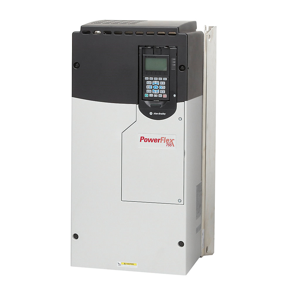
The 20G1ANF034JA0NNNNN is an industrial AC variable frequency drive from the PowerFlex 755 series. It is designed for controlling three-phase AC motors in industrial machinery, automated production systems, process equipment, material-handling systems and other applications requiring adjustable motor speed and controlled motor operation.
This model belongs to the 690 VAC class and has a nominal 34 A output-current rating. Its approximate power rating is 30 kW for normal-duty applications and 22 kW for heavy-duty applications.
The drive uses a Frame 6 mechanical configuration and forced-air cooling. The JA0 configuration is particularly notable because it includes an internal dynamic-braking transistor, making it different from closely related configurations without dynamic-braking capability.
The drive is also designed for integration into industrial automation systems, with embedded Ethernet/IP communication. It can therefore be used as part of a centralized control architecture in which the motor drive communicates with a PLC or other industrial controller.
2. Brand and Series Information
| Item | Information |
|---|---|
| Brand | Allen-Bradley |
| Product family | PowerFlex |
| Product series | PowerFlex 755 |
| Model family | 20G |
| Product type | AC Variable Frequency Drive |
| Voltage class | 690 VAC |
| Mechanical frame | Frame 6 |
| Cooling method | Forced air |
| Communication | Embedded Ethernet/IP |
| Main application | Industrial AC motor control |
| Main function | Variable-speed and torque control |
The PowerFlex 755 series is intended for industrial applications where a higher level of motor control is required than a simple fixed-speed starter can provide.
The series is available in different current and power configurations. This makes it possible to select a drive according to the actual motor current, voltage, duty cycle and mechanical load.
3. Basic Product Parameters
| Parameter | Specification |
|---|---|
| Model | 20G1ANF034JA0NNNNN |
| Brand | Allen-Bradley |
| Series | PowerFlex 755 |
| Product type | AC Variable Frequency Drive |
| Input voltage class | 690 VAC |
| Input phase | Three-phase |
| Output phase | Three-phase |
| Output current | 34 A |
| Normal-duty power | 30 kW |
| Heavy-duty power | 22 kW |
| Frame size | Frame 6 |
| Cooling | Forced air |
| Enclosure type | Open type |
| Protection class | IP20/IP00 |
| Input configuration | AC input with precharge |
| DC terminals | None |
| Filter | Filtered configuration |
| Common-mode configuration | CM jumper installed |
| Dynamic braking | Internal DB transistor |
| HIM | Blank / no HIM |
| Communication | Embedded Ethernet/IP |
| Approx. width | 570 mm |
| Approx. height | 345 mm |
| Approx. depth | 377 mm |
| Approx. dimensions | 570 × 345 × 377 mm |
| Approx. weight | 14.51 kg |
| Installation | Electrical cabinet / industrial control panel |
| Cooling requirement | Forced-air ventilation |
| Main application | Variable-speed AC motor control |
The dimensions and weight are approximate reference values. For a final cabinet design, the exact mechanical drawing and actual drive configuration should be checked because installation clearances, cable routing and accessory requirements can increase the required cabinet space.
4. Detailed Electrical Parameters
| Technical parameter | 20G1ANF034JA0NNNNN |
|---|---|
| Model | 20G1ANF034JA0NNNNN |
| Rated voltage class | 690 VAC |
| Input voltage | 690 VAC class |
| Input phase | 3 phase |
| Output phase | 3 phase |
| Output current | 34 A |
| Normal-duty current | Approximately 34 A |
| Heavy-duty current | Approximately 27 A class |
| Normal-duty motor power | 30 kW |
| Heavy-duty motor power | 22 kW |
| Input frequency | 50/60 Hz class |
| Drive frame | Frame 6 |
| Cooling | Forced air |
| Enclosure | Open type |
| Protection | IP20/IP00 |
| Input precharge | Yes |
| DC terminals | No |
| Input filtering | Filtered |
| CM jumper | Installed |
| Dynamic-braking transistor | Yes |
| Local HIM | Not included |
| Communication | Embedded Ethernet/IP |
| Mounting | Panel/cabinet |
| Approx. dimensions | 570 × 345 × 377 mm |
| Approx. weight | 14.51 kg |
5. Normal-Duty Rating
The normal-duty rating of this model is approximately 30 kW.
Normal-duty applications generally involve relatively moderate overload requirements. Typical examples include fans, centrifugal pumps and general-purpose machinery where the load does not continuously demand very high starting or overload torque.
The 30 kW rating should not be interpreted as meaning that every 30 kW motor can automatically be connected to the drive.
The motor’s actual nameplate current is an important sizing parameter.
The following should normally be considered together:
- Motor rated voltage
- Motor rated current
- Motor power
- Motor frequency
- Load type
- Starting torque
- Acceleration requirements
- Overload requirements
- Operating temperature
6. Heavy-Duty Rating
For heavy-duty applications, the drive is approximately rated at 22 kW.
Heavy-duty applications can involve:
- Higher starting torque
- Frequent acceleration
- Frequent deceleration
- Large mechanical inertia
- Rapid load changes
- High overload requirements
- Repeated starting cycles
Typical examples include:
- Loaded conveyors
- Mixers
- Material-handling machines
- Processing machinery
- High-inertia equipment
- Certain positive-displacement pumping systems
The distinction between normal duty and heavy duty is important when selecting the drive.
A motor with a relatively moderate kW rating may still require a larger drive if the application has a demanding torque profile.
7. 690 VAC Design
One of the most important characteristics of the 20G1ANF034JA0NNNNN is its 690 VAC voltage class.
This makes it suitable for industrial systems using higher-voltage three-phase motors.
Higher-voltage motor systems are commonly used in larger industrial installations because they can provide an appropriate electrical architecture for higher-power machinery.
The drive should be matched to the actual motor and electrical supply.
A 30 kW drive with a different voltage class should not automatically be considered a replacement for this 690 VAC model.
8. Output Current
The drive has an approximately 34 A output-current rating.
Output current is one of the most important drive-sizing parameters.
The motor’s actual full-load current should be compared with the drive’s continuous current capability.
For example, two motors with the same nominal power rating can have different full-load currents because of differences in:
- Motor efficiency
- Power factor
- Rated voltage
- Motor design
- Operating temperature
- Application load
- Motor duty
For replacement applications, the motor nameplate current should therefore be checked before selecting the drive.
9. Dynamic Braking
The JA0 configuration is important because it includes an internal dynamic-braking transistor.
Dynamic braking is used when a motor needs to decelerate while handling energy returned from the motor during braking.
When a high-inertia motor is commanded to slow down, the motor can temporarily operate in a regenerative condition. Energy can return toward the drive’s DC bus.
A braking circuit can provide a controlled path for dissipating this energy through an appropriate braking resistor.
This can be useful for machinery requiring:
- Rapid deceleration
- Controlled stopping
- Frequent stopping
- High-inertia loads
- Conveyor systems
- Centrifuges
- Material-handling machinery
- Certain hoisting-related applications
The presence of the internal braking transistor does not mean that the drive can dissipate unlimited braking energy. The braking resistor and its thermal rating must be correctly matched to the actual application.
10. Difference Between JA0 and JN0 Configurations
The 20G1ANF034JA0NNNNN should not be confused with similar PowerFlex 755 configurations using different option codes.
The JA0 configuration is associated with an internal dynamic-braking transistor.
This is an important consideration when replacing a drive.
| Feature | 20G1ANF034JA0NNNNN | Similar JN0 configuration |
|---|---|---|
| Voltage | 690 VAC | 690 VAC |
| Output current | 34 A | 34 A class |
| Normal-duty power | 30 kW | Similar rating |
| Heavy-duty power | 22 kW | Similar rating |
| Frame | 6 | 6 |
| Cooling | Forced air | Forced air |
| Ethernet/IP | Yes | Yes |
| Filtered | Yes | Yes |
| Dynamic braking | Internal DB transistor | No internal DB transistor |
| HIM | Blank / no HIM | Blank / no HIM |
| Approx. weight | 14.51 kg | Approximately similar |
| Approx. dimensions | 570 × 345 × 377 mm | Approximately similar |
For machinery that requires dynamic braking, the braking configuration should be checked before selecting a replacement.
11. Cooling System
The drive uses forced-air cooling.
The power electronics generate heat during normal operation. Forced airflow removes heat from the power section and helps maintain an acceptable operating temperature.
The cabinet should therefore be designed with appropriate airflow.
Important considerations include:
| Cooling consideration | Description |
|---|---|
| Cabinet ventilation | Must provide adequate airflow |
| Ambient temperature | Higher temperature increases thermal stress |
| Fan operation | Cooling fans should be checked during maintenance |
| Dust | Excessive dust can obstruct airflow |
| Clearance | Adequate space should be maintained around the drive |
| Heat load | Heat from all cabinet components should be considered |
| Air circulation | Hot air should not be continuously recirculated through the drive |
When several drives are installed in one cabinet, the combined heat load needs to be considered.
12. Enclosure and Protection
The drive uses an open-type IP20/IP00 construction.
This type of drive is normally installed inside an electrical control cabinet.
It is not intended to function as a standalone weatherproof motor controller.
The external enclosure should protect the drive against environmental conditions such as:
- Water
- Condensation
- Dust
- Conductive particles
- Oil contamination
- Corrosive materials
- Mechanical impact
The appropriate cabinet protection level depends on the actual installation environment.
13. Ethernet/IP Communication
The drive has embedded Ethernet/IP communication.
This allows it to be integrated into an industrial automation system.
A PLC or other controller can exchange information with the drive.
Typical information includes:
- Start command
- Stop command
- Speed reference
- Actual speed
- Output current
- Drive status
- Fault status
- Alarm information
- Parameter information
- Diagnostic data
This can reduce the amount of hardwired control required in a large automated machine.
14. No Local HIM
The specified configuration is a blank / no-HIM configuration.
This means the drive does not rely on a permanently installed local operator interface for normal machine operation.
In a centralized automation system, the drive can instead be controlled through the industrial network.
A typical architecture can be:
PLC → Ethernet/IP → Drive → Motor
The operator may interact with the PLC or HMI rather than directly operating the drive.
This arrangement is common in automated production machinery.
15. AC Input With Precharge
The drive uses an AC input configuration with precharge.
The internal DC-link capacitors require controlled charging when the drive is energized.
Precharge helps limit the initial charging current and provides a controlled startup sequence for the drive’s DC-link system.
This is particularly important in higher-power electronic drive systems.
16. Filtering
The specified configuration includes filtering.
Variable-frequency drives use high-frequency switching devices to generate the motor output waveform.
These switching actions can generate electrical noise.
The filtered configuration helps manage electrical interference within the electrical installation.
Correct installation remains important.
Recommended installation practices include:
- Proper grounding
- Appropriate motor cable selection
- Correct cable shielding
- Separation between power and signal cables
- Suitable cabinet layout
- Correct termination of shields and grounds
17. Common-Mode Configuration
The configuration includes a CM jumper installed arrangement.
Common-mode components can influence high-frequency electrical behavior and leakage currents.
The configuration should be maintained according to the requirements of the actual electrical system.
The grounding and motor-cable arrangement should be considered together with the drive configuration.
18. Product Applications
18.1 Conveyor Systems
The 20G1ANF034JA0NNNNN is suitable for industrial conveyor systems where motor speed needs to be adjusted.
Typical functions include:
- Controlled starting
- Adjustable speed
- Controlled stopping
- Production-line synchronization
- Material-flow control
Dynamic braking can be particularly useful where the conveyor has significant rotating inertia or requires relatively fast stopping.
18.2 Pumping Equipment
The drive can be used for industrial pumps where flow or pressure needs to be adjusted.
Typical applications include:
- Process-water pumps
- Cooling-water pumps
- Circulation systems
- Industrial fluid-transfer systems
- Manufacturing process pumps
Variable-speed operation can reduce the need to operate a pump continuously at full speed.
18.3 Fans and Blowers
Fans and blowers often operate at different airflow requirements depending on production conditions.
The drive can vary motor speed to match the required operating condition.
Typical applications include:
- Industrial ventilation
- Exhaust systems
- Cooling systems
- Air-handling equipment
- Process ventilation
18.4 Mixers
Industrial mixers can require controlled acceleration and adjustable speed.
The drive can be used to control the motor during:
- Startup
- Mixing
- Processing
- Speed changes
- Shutdown
The exact motor and drive rating should be selected according to the material being mixed and the required torque.
18.5 Material-Handling Equipment
The drive is suitable for many material-handling applications.
Examples include:
- Conveyors
- Feeders
- Transfer equipment
- Production-line material handling
- Automated movement systems
Controlled acceleration can reduce mechanical shock to belts, gears, couplings and shafts.
18.6 High-Inertia Machines
The internal braking transistor makes this configuration particularly interesting for applications where controlled deceleration is required.
Examples can include:
- Large rotating machinery
- High-inertia conveyors
- Certain centrifuge applications
- Rapid-cycle production machinery
The complete braking resistor arrangement must be designed according to the application’s braking energy.
19. Product Advantages
19.1 690 VAC Industrial Capability
The drive is designed for a higher-voltage industrial motor system.
This makes it suitable for machinery using 690 VAC class motors and distribution systems.
19.2 34 A Output Capacity
The 34 A output rating provides a useful capacity for medium-power industrial motor applications.
The approximately 30 kW normal-duty rating provides substantial motor-control capacity within the Frame 6 product range.
19.3 30 kW Normal-Duty Rating
The 30 kW normal-duty rating makes this model suitable for applications where the motor operates under relatively moderate overload conditions.
This can include pumps, fans, blowers and general industrial machinery.
19.4 22 kW Heavy-Duty Rating
The 22 kW heavy-duty rating provides a lower power rating for applications requiring greater overload capability.
This makes the drive suitable for more demanding load profiles than a simple kW comparison might suggest.
19.5 Internal Dynamic-Braking Transistor
The internal DB transistor is one of the notable features of the JA0 configuration.
It can simplify the design of applications requiring dynamic braking because the drive already contains the switching element required for the braking circuit.
A correctly selected external braking resistor is still required where the application needs dynamic braking.
19.6 Ethernet/IP Integration
Embedded Ethernet/IP allows the drive to participate in centralized automation.
This can be useful for:
- Production-line control
- Centralized monitoring
- Fault management
- Speed control
- Machine diagnostics
- Drive parameter management
19.7 Forced-Air Cooling
Forced-air cooling is suitable for properly ventilated industrial cabinets.
It provides a practical cooling arrangement for this power level.
19.8 Broad Product Family
The PowerFlex 755 family provides multiple current and voltage configurations.
This allows equipment manufacturers to use a common drive platform across different motor sizes.
20. Five Recommended Models From the Same Series
The following five models are closely related to the 20G1ANF034JA0NNNNN and can be considered when selecting another PowerFlex 755 configuration.
| Model | Voltage | Output current | Normal-duty power | Heavy-duty power | Frame | Cooling | Approx. dimensions | Approx. weight |
|---|---|---|---|---|---|---|---|---|
| 20G1ANF023JA0NNNNN | 690 VAC | 23 A | 18.5 kW | 15 kW | Frame 6 | Forced air | Approx. 570 × 345 × 377 mm | Approx. 14.51 kg |
| 20G1ANF030JA0NNNNN | 690 VAC | 30 A | 22 kW | 18.5 kW | Frame 6 | Forced air | Approx. 570 × 345 × 377 mm | Approx. 14.51 kg |
| 20G1ANF034JA0NNNNN | 690 VAC | 34 A | 30 kW | 22 kW | Frame 6 | Forced air | Approx. 570 × 345 × 377 mm | Approx. 14.51 kg |
| 20G1ANF046JA0NNNNN | 690 VAC | 46 A | 37 kW | 30 kW | Frame 6 | Forced air | Approx. 570 × 345 × 377 mm* | Approx. 14.51 kg* |
| 20G1ANF052JA0NNNNN | 690 VAC | 52 A class | Higher power class | Higher HD class | Frame 6 | Forced air | Approx. Frame 6 dimensions* | Approx. 14.51 kg* |
The models above are useful for comparing nearby current and power ratings within the same product family.
The 23 A and 30 A versions are useful when the required motor size is lower than the 34 A configuration, while the 46 A and larger configurations can be considered when additional current capacity is required.
*Approximate physical values for related models should be confirmed against the exact configuration before final cabinet design.
21. Same-Series Model Comparison
| Specification | 20G1ANF023JA0NNNNN | 20G1ANF030JA0NNNNN | 20G1ANF034JA0NNNNN | 20G1ANF046JA0NNNNN |
|---|---|---|---|---|
| Voltage class | 690 VAC | 690 VAC | 690 VAC | 690 VAC |
| Output current | 23 A | 30 A | 34 A | 46 A |
| Normal-duty power | 18.5 kW | 22 kW | 30 kW | 37 kW |
| Heavy-duty power | 15 kW | 18.5 kW | 22 kW | 30 kW |
| Frame | 6 | 6 | 6 | 6 |
| Cooling | Forced air | Forced air | Forced air | Forced air |
| Enclosure | IP20/IP00 | IP20/IP00 | IP20/IP00 | IP20/IP00 |
| Ethernet/IP | Yes | Yes | Yes | Yes |
| Dynamic-braking transistor | Yes | Yes | Yes | Yes |
| HIM | None | None | None | None |
| Approx. dimensions | 570 × 345 × 377 mm* | 570 × 345 × 377 mm* | 570 × 345 × 377 mm | 570 × 345 × 377 mm* |
| Approx. weight | 14.51 kg* | 14.51 kg* | 14.51 kg | 14.51 kg* |
This comparison shows how the same general architecture can be used across several motor-power levels.
22. Five Related Popular Models Under the Same Brand
For applications where a different product series is acceptable, the following models provide additional options from the same brand’s drive portfolio.
They should not be treated as direct replacements without checking voltage, current, power, braking, communication and mechanical requirements.
| Model | Product series | Voltage class | Output current / rating | Typical power class | Cooling | Approx. dimensions | Approx. weight |
|---|---|---|---|---|---|---|---|
| 20G1ANF030JA0NNNNN | PowerFlex 755 | 690 VAC | 30 A | 22 kW ND / 18.5 kW HD | Forced air | Approx. 570 × 345 × 377 mm | Approx. 14.51 kg |
| 20G1ANF046JA0NNNNN | PowerFlex 755 | 690 VAC | 46 A | 37 kW ND / 30 kW HD | Forced air | Approx. 570 × 345 × 377 mm* | Approx. 14.51 kg* |
| 20F11ND034AA0NNNNN | PowerFlex 753 | 480 VAC class | Approx. 34 A | Approx. 22 kW class | Forced air | Configuration dependent | Approx. 10–15 kg* |
| 25B-D030N114 | PowerFlex 525 | 480 VAC class | Approx. 30 A | Approx. 15 kW class | Fan cooled | Compact frame | Approx. 7 kg* |
| 25B-D017N114 | PowerFlex 525 | 480 VAC class | Approx. 17 A | Approx. 7.5 kW class | Fan cooled | Compact frame | Approx. 4 kg* |
The first two models are the closest alternatives because they remain within the PowerFlex 755 family.
The PowerFlex 753 and PowerFlex 525 models are more appropriate when the machine has different voltage, size or control requirements.
23. Application Comparison
| Application | Suitability | Main reason |
|---|---|---|
| Conveyor | High | Adjustable speed and controlled acceleration |
| Pump | High | Variable-speed flow control |
| Fan | High | Adjustable airflow |
| Blower | High | Variable process airflow |
| Mixer | High | Adjustable motor speed |
| Material handling | High | Controlled motor operation |
| High-inertia machinery | Suitable with correct braking design | Internal DB transistor |
| Production line | High | Networked motor control |
| Process machinery | High | Variable speed and automation integration |
| Fixed-speed simple motor | May be unnecessary | VFD functionality may exceed requirements |
24. Cabinet Installation
The approximate dimensions of the drive are:
570 mm × 345 mm × 377 mm
with an approximate weight of:
14.51 kg
The physical dimensions should not be used as the complete cabinet envelope.
Additional space may be required for:
- Input power cables
- Motor cables
- Control cables
- Ethernet cable
- Grounding connections
- Airflow
- Terminal access
- Maintenance
- Cooling
- Braking-resistor connections
The drive should be mounted securely because the complete assembly weighs approximately 14.51 kg.
25. Thermal Management
A drive of this power level can generate a considerable amount of heat.
When installing the unit in a cabinet, the following should be considered:
| Thermal factor | Importance |
|---|---|
| Ambient temperature | High |
| Cabinet airflow | High |
| Drive cooling fan | High |
| Cabinet heat load | High |
| Neighboring drives | High |
| Dust accumulation | Medium to high |
| Air inlet/outlet arrangement | High |
| Internal cabinet temperature | High |
A cabinet that is physically large enough may still be thermally unsuitable if airflow is insufficient.
26. Dynamic Braking Application Considerations
The internal braking transistor makes the JA0 configuration useful for applications that require dynamic braking.
However, dynamic braking should be designed according to:
- Motor inertia
- Load inertia
- Desired stopping time
- Number of braking cycles
- Motor speed
- DC-bus energy
- Braking-resistor rating
- Resistor duty cycle
- Ambient temperature
The braking resistor must be capable of handling the energy generated during the actual braking cycle.
For applications involving frequent rapid stops, the braking system should be sized according to the worst operating condition rather than the average operating condition.
27. Advantages in Automated Machinery
The combination of variable-speed operation and network communication makes this drive particularly useful in automated machinery.
For example, a production line can use the drive to:
- Receive a speed command from the controller.
- Accelerate the motor according to a defined ramp.
- Maintain the required operating speed.
- Monitor motor operating conditions.
- Detect faults.
- Reduce speed when the production process changes.
- Decelerate when the machine stops.
- Report drive status back to the controller.
This provides much greater control than a simple contactor-based motor starter.
28. Maintenance and Service Considerations
Routine inspection is important for long-term operation.
| Component / area | Inspection item |
|---|---|
| Cooling fan | Operation and abnormal noise |
| Air passages | Dust and obstruction |
| Power terminals | Loose connections and heat marks |
| Motor cables | Insulation and connection |
| Grounding | Connection condition |
| Cabinet | Dust and moisture |
| Ethernet/IP cable | Connection integrity |
| Braking circuit | Resistor and wiring condition |
| Drive alarms | Alarm history |
| Drive faults | Fault history |
| Ambient temperature | Operating environment |
Maintenance frequency should be adjusted according to actual operating conditions.
29. Important Selection Factors
When choosing the 20G1ANF034JA0NNNNN for a new machine or replacement project, the following parameters should be checked.
| Selection factor | Required check |
|---|---|
| Motor voltage | Must match drive application |
| Supply voltage | Must match 690 VAC class |
| Motor current | Must be within applicable drive rating |
| Motor power | Compare with ND/HD rating |
| Duty type | Normal or heavy duty |
| Acceleration | Check motor and load inertia |
| Deceleration | Check braking requirements |
| Dynamic braking | JA0 configuration provides DB transistor |
| Communication | Confirm Ethernet/IP requirements |
| Cabinet size | Confirm dimensions and clearance |
| Cooling | Confirm adequate airflow |
| Environment | Check temperature, dust and humidity |
| Motor cable | Check cable length and construction |
| Grounding | Confirm system grounding |
| Maintenance access | Allow adequate service space |
30. Model Number and Configuration Significance
The catalog number 20G1ANF034JA0NNNNN is not simply a model name.
The individual sections identify different aspects of the drive configuration.
The important practical information represented by the model includes:
- PowerFlex 755 family
- 690 VAC class
- 34 A current class
- Frame 6 mechanical arrangement
- JA configuration
- Dynamic-braking transistor
- Filter configuration
- Communication configuration
- Operator-interface configuration
This is why two drives that appear almost identical can have different electrical capabilities.
For replacement work, the complete catalog number should be compared rather than selecting a drive solely from the nominal motor power.
31. Quick Reference Table
| Category | 20G1ANF034JA0NNNNN |
|---|---|
| Model | 20G1ANF034JA0NNNNN |
| Brand | Allen-Bradley |
| Series | PowerFlex 755 |
| Voltage | 690 VAC |
| Phase | Three-phase |
| Output current | 34 A |
| Normal-duty power | 30 kW |
| Heavy-duty power | 22 kW |
| Frame | Frame 6 |
| Cooling | Forced air |
| Enclosure | Open type |
| Protection | IP20/IP00 |
| Ethernet/IP | Yes |
| HIM | None / blank |
| Dynamic braking | Internal DB transistor |
| Input precharge | Yes |
| DC terminals | None |
| Filter | Yes |
| CM jumper | Installed |
| Dimensions | 570 × 345 × 377 mm |
| Weight | 14.51 kg |
| Main applications | Pumps, fans, conveyors, mixers, material handling, process machinery |
| Installation | Industrial electrical cabinet |
32. Final Product Summary
The 20G1ANF034JA0NNNNN is a high-capacity industrial variable-frequency drive in the PowerFlex 755 series.
It is designed for 690 VAC three-phase motor systems and provides approximately 34 A output current, 30 kW normal-duty capacity and 22 kW heavy-duty capacity.
Its Frame 6 construction, forced-air cooling, Ethernet/IP communication, filtered configuration and open-type IP20/IP00 enclosure make it suitable for integration into industrial control panels and automated production equipment.
One of the most significant characteristics of this particular model is its internal dynamic-braking transistor. This provides an important advantage in applications where controlled deceleration is required, although the external braking resistor must still be selected according to the actual braking energy and duty cycle.
The approximate physical dimensions are 570 × 345 × 377 mm, and the approximate weight is 14.51 kg. These figures are useful for product comparison and preliminary cabinet planning, while the exact mechanical drawing should be used for final installation.
The drive can be used for conveyors, pumps, fans, blowers, mixers, material-handling systems, production machinery, process equipment and high-inertia applications where variable motor speed and controlled acceleration/deceleration are required.
Its main advantages include 690 VAC operation, 34 A output capability, 30 kW normal-duty capacity, 22 kW heavy-duty capability, Ethernet/IP integration, forced-air cooling, filtered electrical configuration, Frame 6 construction and an internal dynamic-braking transistor.
For applications requiring a similar drive with a different power rating, the 20G1ANF023JA0NNNNN, 20G1ANF030JA0NNNNN, 20G1ANF046JA0NNNNN and other PowerFlex 755 configurations provide useful alternatives.
For a broader product selection, the PowerFlex 753 and PowerFlex 525 families provide options for applications requiring different voltage classes, power ranges, physical sizes or machine-control architectures.
When selecting a replacement or designing a new system, the most important factors are the motor nameplate voltage, motor full-load current, motor kW, duty classification, overload requirement, acceleration/deceleration characteristics, braking requirements, communication method, cabinet dimensions, cooling conditions and installation environment.
The JA0 configuration should be specifically identified when dynamic braking is required. A similar model with a different option code may have the same voltage and current rating but may not provide the same braking hardware.