

ProductPRODUCT
Featured products
Contact Us
- Honeywell
- 05704-A-0148
- 5704F Fire Status Panel
- USA
- 172 × 25 × 132 mm
- 0.5 kg
- Xiamen, China
- New & In Stock
- T/T, PayPal, Western Union
- 1 Year
- 1-3 Working Days
- DHL, UPS, TNT, FedEx and EMS.
- 24-Hour Service
- COO
- 4
Our advantage

Global Logistics
We have a 10-year logistics and express cooperation agreement, so our products can be shipped to any place in the world.

Brand new and original
Our products are imported in bulk from the place of origin. Because of the cooperative relationship, our products are all original and 100% new.

24-hour service
We provide 7*24 hours service to our customers. We will be there whenever you need us.

Price advantage
All our products are priced very favorably because we have our own warehouse and supply.
| Company Information | |||
| [email protected] | |||
| Mobile | +8615980777398 | ||
| +8615980777398 | |||
| 15980777398 |
Product Overview
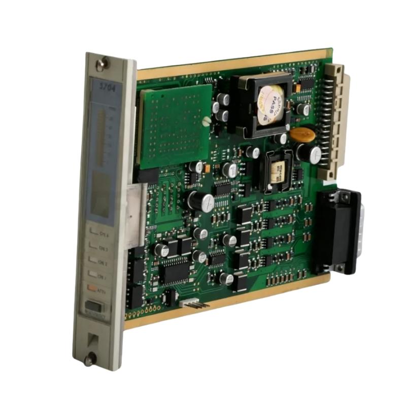
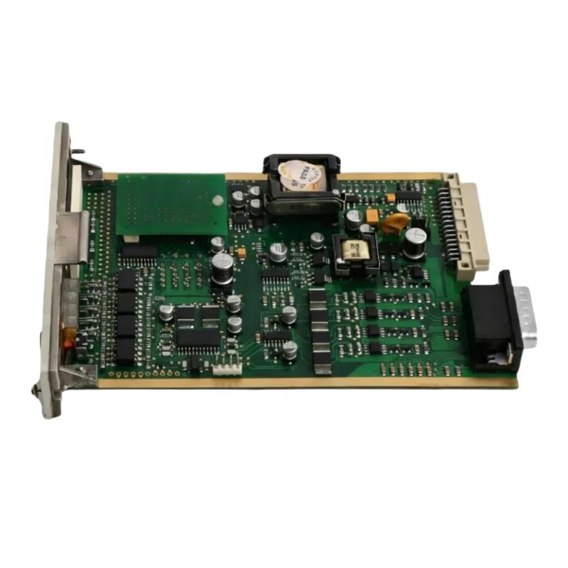
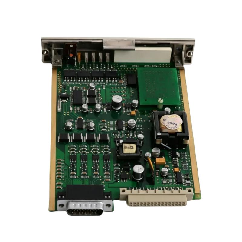
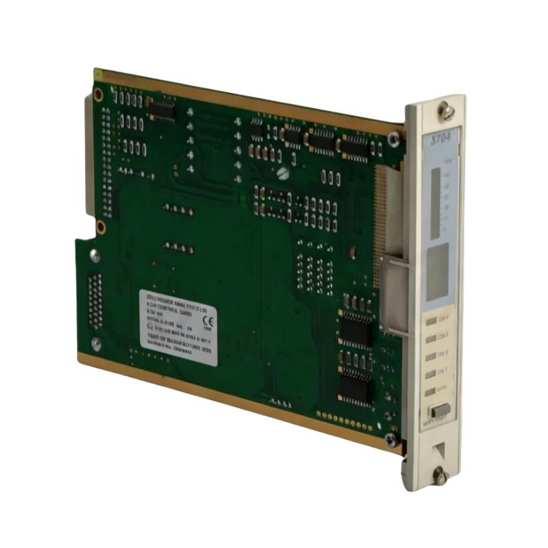
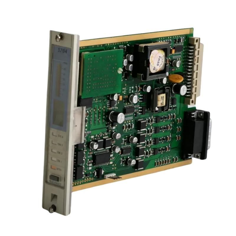
The Honeywell 05704-A-0148 is a 5704F Fire Status Panel belonging to the System 57 fire and gas detection platform. It provides centralized visual and audible status indication for fire detection equipment installed in a rack, allowing operators to identify fire alarms, faults, inhibited channels, and other system conditions from a common front-panel interface.
In an industrial fire detection cabinet, multiple 5704F Fire Control Cards may monitor different detection channels. Checking each card individually can make routine operation and alarm acknowledgment more cumbersome. The Fire Status Panel consolidates common indications and operator controls into one accessible location, helping personnel assess the overall status of the fire detection system.
The panel includes LED indicators for Fire, Fault, Inhibit, Select, Walk Test, Earth Fault, and Power. It also incorporates an audible sounder and push-button controls for functions such as Accept, Silence, Reset, and Lamp Test. Channel-related functions include Walk Test and Inhibit, allowing authorized personnel to carry out designated operating and maintenance actions through the associated system.
The 05704-A-0148 connects to a compatible 5704F Fire Control Card through a short flying lead and is installed immediately to the right of the associated card. One Fire Status Panel is required per rack in the documented arrangement. Its function is supervisory indication and operator interaction; the connected fire control cards and associated detection equipment perform the underlying monitoring functions.
Technical Specifications
| Parameter | Specification |
|---|---|
| Manufacturer | Honeywell |
| Model | 05704-A-0148 |
| Product Family | System 57 |
| Product Type | 5704F Fire Status Panel |
| Compatible System | Honeywell System 57 / 5704F |
| Installation Format | Rack-mounted front-panel module |
| Panel Height | 3U |
| Front-Panel Width | 25 mm |
| Supply Voltage | 18–32 V DC |
| Power Consumption | 0.75 W |
| Status Indicators | Fire, Fault, Inhibit, Select, Walk Test, Earth Fault, Power |
| Audible Alarm | Integrated sounder |
| Operator Controls | Accept, Silence, Reset, Lamp Test, Walk Test, Inhibit |
| Connection | Flying lead to the associated Fire Control Card |
| Dimensions | 172 × 25 × 132 mm |
| Weight | 0.5 kg |
Product Features
- Centralized fire status indication: Displays common fire detection system conditions through dedicated front-panel indicators.
- Audible alarm notification: Provides an audible indication of designated fire and fault events.
- Common operator controls: Supports alarm acceptance, sounder silencing, reset, and lamp testing.
- Channel-level functions: Provides Walk Test and Inhibit controls for supported maintenance and operating procedures.
- System 57 integration: Works with compatible 5704F Fire Control Cards within the established rack arrangement.
- Flying-lead connection: Connects to the designated header on the associated Fire Control Card.
- Rack-level status monitoring: Allows personnel to review common system indications without checking every control card separately.
Working Principle
The 05704-A-0148 receives its operating power and status information through its connection to the associated Fire Control Card. It presents the relevant system conditions through front-panel LEDs and an audible sounder, giving operators a common point for reviewing alarm and fault indications.
A simplified arrangement is:
Fire Detection Devices → 5704F Fire Control Cards → Fire Status Panel → Operator Indication and Control
When a fire or fault condition is reported by the associated control system, the panel displays the corresponding status indication. The sounder provides an additional alert for designated events, helping draw attention to conditions that require operator assessment.
The front-panel controls allow authorized personnel to acknowledge or silence audible indications, reset supported conditions, and perform lamp testing. Walk Test and Inhibit functions support designated channel-level operations when used with the appropriate control-card and system configuration.
The panel does not independently detect combustible gases, smoke, or fire. It displays and supports interaction with conditions handled by the connected System 57 equipment. Actual detection, alarm evaluation, relay operation, and protective actions depend on the configuration of the fire control cards, field devices, and associated system logic.
During commissioning, the panel’s indicators, sounder, controls, and connection to the designated Fire Control Card should be checked against the system’s approved test procedure. In a live installation, alarm acceptance, silencing, reset, and inhibition must follow site safety procedures and the applicable fire protection strategy.
Role in the Honeywell System 57 Fire Detection Architecture
The 05704-A-0148 occupies the operator interface layer of the System 57 fire detection rack. It consolidates common status indications and provides local controls, while the Fire Control Cards process detection inputs and the wider system handles configured alarm responses.
Fire and Gas Detection Devices → 5704F Fire Control Cards → 05704-A-0148 Fire Status Panel → Operator Response
| System Element | Function |
|---|---|
| 05704-A-0148 Fire Status Panel | Displays common fire and fault conditions and provides operator controls |
| 5704F Fire Control Card | Processes the associated detection channels and system conditions |
| Engineering Card | Supports system configuration and designated engineering functions |
| Field Detection Devices | Supply detection signals to the configured control channels |
| Relay Interface Assembly | Provides relay outputs for configured external alarm or control circuits |
| System 57 Rack | Houses the control cards, status panel, and associated hardware |
| Plant Alarm Interface | Receives configured alarm or status signals where provided |
| Operator | Reviews indications and follows the site’s response procedures |
Industrial Applications
| Application | Practical Use |
|---|---|
| Industrial Fire Detection Cabinets | Centralizing fire and fault indications from compatible 5704F cards |
| Oil and Gas Facilities | Providing a common status interface for installed fire detection systems |
| Petrochemical Plants | Supporting operator awareness of configured fire detection conditions |
| Power Generation Facilities | Displaying fire system status within dedicated control racks |
| Chemical Processing Plants | Supporting alarm acknowledgment and maintenance operations |
| Industrial Utility Rooms | Providing local indication for compatible System 57 installations |
| Process Control Rooms | Allowing personnel to review rack-level fire system conditions |
| Fire Detection System Maintenance | Supporting lamp tests, alarm acknowledgment, and designated channel tests |
| System 57 Rack Refurbishment | Replacing a matching status panel while retaining the existing rack arrangement |
| Industrial Safety Instrumentation | Providing operator-facing indications as part of the configured fire detection architecture |
Installation and Maintenance
- Verify the complete model reference: Confirm 05704-A-0148 and ensure that the panel matches the installed System 57 / 5704F configuration.
- Check the rack arrangement: Identify the associated Fire Control Card and confirm the required mounting position immediately to its right.
- Inspect the flying lead: Check the cable, connector, and mating header for damage, contamination, or signs of mechanical strain.
- Isolate the equipment as required: Follow the approved maintenance procedure before removing or reconnecting the panel.
- Check the mounting position: Ensure the panel fits the designated rack opening and does not interfere with adjacent cards or front-panel components.
- Connect the flying lead: Attach the lead to the correct header on the associated Fire Control Card without forcing the connector.
- Inspect the front-panel indicators: Check the LED lenses and labels for damage or obscured markings.
- Check the operator controls: Inspect the push-buttons for mechanical damage and confirm that they move correctly.
- Verify the supply connection: Confirm that the panel receives power through the intended control-card connection and operates within the specified supply range.
- Test the audible sounder: Use the approved commissioning or maintenance procedure to verify the sounder response without disrupting required site alarm coverage.
- Verify control functions: Test Accept, Silence, Reset, Lamp Test, Walk Test, and Inhibit functions as applicable, ensuring that any inhibited channels are restored afterward.
- Record the maintenance results: Document the panel reference, associated control card, functional test results, and any defects requiring follow-up.
Compatible System Components
| Component | Function |
|---|---|
| Honeywell 05704-A-0148 | Provides common fire status indication and operator controls |
| Honeywell 05704-A-0146 | 5704F Fire Control Card for the associated detection system |
| Honeywell 05704-A-0133 | 5704F Relay Interface Assembly for configured relay functions |
| Honeywell 05704-A-0123 | 5704F Hex Relay Interface Card |
| Honeywell System 57 Engineering Card | Supports system configuration and engineering functions |
| Honeywell System 57 Rack | Houses compatible control cards and the status panel |
| Honeywell System 57 DC Input Card | Supplies the rack’s configured DC power arrangement |
| Fire Detection Devices | Provide field signals to the configured detection channels |
| Alarm and Indication Circuits | Use the configured outputs to communicate system conditions |
Recommended Related Models
| Model | Product Type | Typical Application |
|---|---|---|
| Honeywell 05704-A-0146 | 5704F Fire Card | Processing fire detection channel signals |
| Honeywell 05704-A-0133 | 5704F Fire Relay Interface Assembly | Providing configured relay interfaces for external circuits |
| Honeywell 05704-A-0123 | 5704F Hex Relay Interface Card | Interfacing control-card signals with field wiring |
| Honeywell 05704-A-0144 | 5704 Four-Channel Control Card, Catalytic | Monitoring compatible catalytic detection channels |
| Honeywell 05704-A-0145 | 5704 Four-Channel Control Card, 4–20 mA | Monitoring compatible 4–20 mA detection inputs |
| Honeywell 05704-C-0160 | 5704 Interconnect Cable | Providing the designated interconnection for compatible 5704 system hardware |
Key Advantages
- Consolidates common fire detection status indications at the rack level.
- Combines visual indicators with an audible alert for designated events.
- Provides common and channel-level operator controls.
- Integrates with compatible 5704F Fire Control Cards through the designated flying-lead connection.
- Supports routine functional testing and maintenance of the System 57 fire detection rack.
Technical FAQs
How many Fire Status Panels are required in a System 57 rack?
The documented 5704F arrangement uses one Fire Status Panel per rack. The panel is installed immediately to the right of an associated Fire Control Card and connected through its flying lead.
Which operating functions are available from the 05704-A-0148 front panel?
The panel provides common controls for Accept, Silence, Reset, and Lamp Test, along with Walk Test and Inhibit functions for supported channel-level operations. The exact operating procedure depends on the installed control cards and system configuration.
Does the 05704-A-0148 perform fire detection independently?
No. It provides common status indication and operator interaction for the connected fire detection system. Detection inputs and associated alarm processing are handled by the compatible Fire Control Cards and their configured field devices.
What should be checked if the panel powers up but does not display the expected status?
Inspect the flying-lead connection, associated Fire Control Card, rack power arrangement, and system configuration. Then verify the relevant detection channel and status indications using the approved commissioning or troubleshooting procedure.