

ProductPRODUCT
Featured products
Contact Us
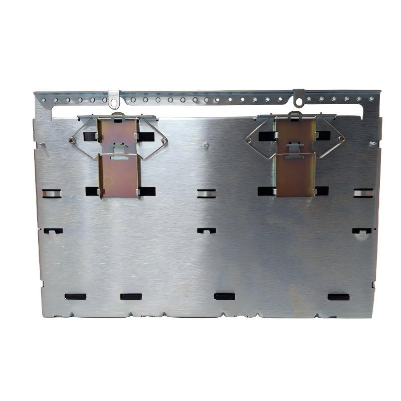
- GE
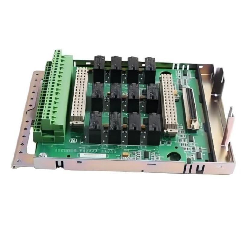
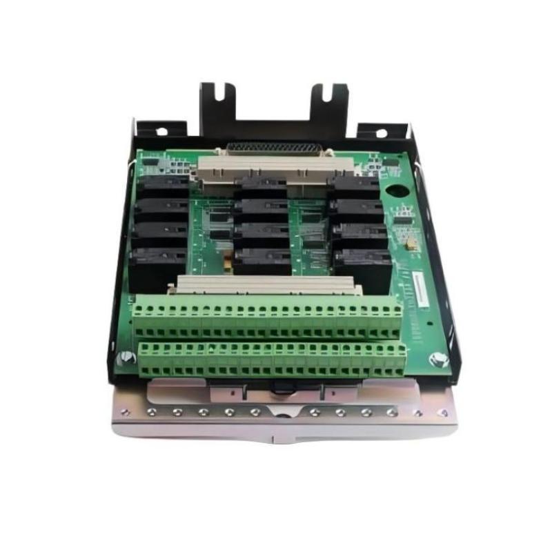
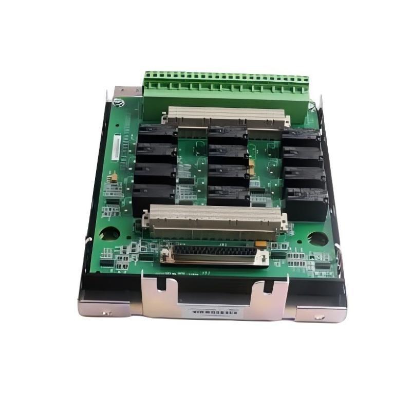
- IS230SRLYH2A IS200SRLYH2AAA
- Digital Output DIN Rail Module
- USA
- 225 x 167 x 55 mm
- 0.5 kg
- Xiamen, China
- New & In Stock
- T/T, PayPal, Western Union
- 1 Year
- 1-3 Working Days
- DHL, UPS, TNT, FedEx and EMS.
- 24-Hour Service
- COO
- 5
Our advantage

Global Logistics
We have a 10-year logistics and express cooperation agreement, so our products can be shipped to any place in the world.

Brand new and original
Our products are imported in bulk from the place of origin. Because of the cooperative relationship, our products are all original and 100% new.

24-hour service
We provide 7*24 hours service to our customers. We will be there whenever you need us.

Price advantage
All our products are priced very favorably because we have our own warehouse and supply.
| Company Information | |||
| [email protected] | |||
| Mobile | +8615980777398 | ||
| +8615980777398 | |||
| 15980777398 |
Product Overview
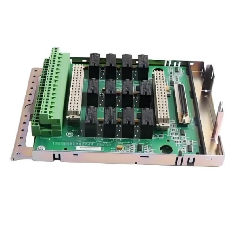
The GE IS230SRLYH2A / IS200SRLYH2AAA Digital Output DIN Rail Module is identified as an industrial control component for use in compatible GE automation systems. Digital output modules generally provide an interface through which a controller sends discrete control commands to external devices. These commands represent defined states, such as ON or OFF, and are commonly used to operate relays, solenoids, indicator devices, and other compatible control equipment.
In industrial automation, digital outputs connect programmed control logic with physical actions in the field. A controller may use an output command to enable equipment, activate an interposing relay, signal an operating condition, or initiate a sequence. The associated output hardware and wiring must match the electrical requirements of the connected device to ensure safe and reliable operation.
The product identification supplied includes IS230SRLYH2A and IS200SRLYH2AAA, together with the description Digital Output DIN Rail Module. Because a model designation and product description alone do not establish the precise relationship between two part numbers, their compatibility and intended function should be confirmed against the original hardware markings and the applicable GE system documentation before ordering or replacement.
The listed physical dimensions are 225 × 167 × 55 mm, and the listed weight is approximately 0.5 kg. These specifications support physical identification, cabinet-layout planning, and replacement logistics.
Technical Specifications
| Parameter | Specification |
|---|---|
| Manufacturer | General Electric (GE) |
| Model Identification | IS230SRLYH2A / IS200SRLYH2AAA |
| Product Type | Digital Output DIN Rail Module |
| Product Family | GE IS200 / IS230 Series |
| Primary Function | Digital output interface, subject to hardware verification |
| Signal Category | Discrete output |
| General System Role | Transfers discrete control commands to compatible external circuits |
| Installation Format | DIN rail module, as identified in the supplied description |
| Dimensions | 225 × 167 × 55 mm |
| Weight | 0.5 kg |
| Electrical Ratings | Confirm against the applicable hardware documentation |
| Output Channel Count | Confirm against the applicable hardware documentation |
| Host-System Compatibility | Verify before installation |
Note: Output voltage, current rating, switching characteristics, channel count, terminal assignments, isolation specifications, and supported load types must be confirmed for the exact assembly and revision.
Understanding Digital Output Technology
Digital output hardware allows a control system to issue discrete commands to connected equipment. Unlike analog outputs, which represent a continuously variable reference, digital outputs typically indicate a defined state.
For example, a controller may command an output to activate a relay when a process condition is satisfied. The relay may then operate a downstream circuit, provided the output interface and electrical design are suitable for that application.
A typical control path can be represented as:
Controller Logic → Digital Output Hardware → Terminal or Field Wiring → Compatible Device → Physical Action
The exact arrangement for the GE IS230SRLYH2A / IS200SRLYH2AAA must be verified for the installed system. The product should not be assumed to support a particular voltage, current, load type, or switching arrangement without confirmation.
Function and Working Principle
1. Discrete Command Processing
The controller evaluates its programmed logic, input conditions, interlocks, and operating states. When the required conditions are met, it issues a discrete command to the relevant output point.
The associated output hardware provides the electrical interface needed to represent that command in the connected circuit.
2. Output Switching
Depending on the specific hardware design, a digital output module may use electronic switching elements or relay-based circuitry to control an external circuit. The implementation used by this particular GE assembly should be verified from its technical documentation.
The receiving device must be compatible with the output’s electrical characteristics. Connecting an unsuitable load can cause malfunction or damage.
3. Field Device Activation
A valid output command may activate a compatible relay, solenoid, indicator, or other discrete-control device. The resulting physical action depends on the field wiring, connected equipment, and control logic.
For example, an automation sequence may issue an output command to enable an auxiliary device after the necessary permissive conditions have been satisfied.
4. Feedback and Status Monitoring
In many control systems, output commands are monitored alongside feedback signals from the controlled equipment. The controller may compare the intended command with an available status input to determine whether the expected response occurred.
Feedback is a separate function and should not be assumed to be provided by the digital output module itself.
Role in Industrial Automation Systems
Digital output interfaces are an important link between programmed control functions and field equipment. They allow the automation system to execute discrete actions in response to operator commands, sensor states, sequence logic, or process conditions.
Within a compatible GE control architecture, the IS230SRLYH2A / IS200SRLYH2AAA may form part of an output-wiring arrangement connecting control electronics to external circuits. Its exact place in the architecture depends on the verified hardware configuration.
Typical system-level uses of digital output technology include:
- Activating compatible control devices.
- Sending discrete commands to external equipment.
- Supporting automatic operating sequences.
- Communicating defined status or enable signals.
- Coordinating equipment operation with control logic.
- Supporting maintenance diagnostics through system-level monitoring.
These functions describe digital output technology in general. The specific capabilities of this assembly must be established from the actual installed hardware.
Industrial Applications
Power Generation
Power generation facilities use discrete control signals for auxiliary equipment, equipment enables, and operating sequences. Digital output interfaces can support these functions when the module is approved for the particular control system and connected load.
Gas Turbine Control
Gas turbine installations contain numerous control and auxiliary circuits that operate according to defined logic and permissive conditions. A compatible digital output interface may form part of the wider control architecture. Suitability for a specific turbine-control function must be verified before installation.
Industrial Manufacturing
Production systems often use discrete commands to operate relays, machine interfaces, indicators, and auxiliary devices. Digital outputs help coordinate these actions with the programmed sequence.
Process Automation
Industrial process facilities may use discrete outputs for equipment enable commands, valve-control interfaces, alarms, and other defined control actions, depending on the system design.
Utility and Auxiliary Equipment
Pumps, ventilation systems, and other auxiliary equipment may use discrete control signals as part of their operating logic. The output hardware and connected device must have compatible electrical requirements.
These are common application areas for digital output technology, not a confirmation that every listed application is supported by this particular GE assembly.
Installation and System Integration
Correct installation requires verification of the part number, mounting arrangement, wiring, and electrical compatibility. The product description should not be used as a substitute for the approved hardware documentation.
1. Verify the Model Identification
Confirm the complete model designation and the markings on the original assembly:
- IS230SRLYH2A
- IS200SRLYH2AAA
Determine whether these identifiers represent an approved assembly relationship, a replacement designation, or separate hardware variants in the intended system. Do not assume they are interchangeable solely because they appear together in a product listing.
2. Confirm the DIN Rail Mounting Arrangement
Check that the module’s mounting mechanism matches the intended DIN rail or assembly arrangement. Inspect the rail, retaining features, and surrounding components for damage or deformation.
The listed dimensions are 225 × 167 × 55 mm, and the listed weight is 0.5 kg. Ensure that the installation location provides sufficient space for wiring, connector access, and maintenance.
3. Verify Electrical Requirements
Before connecting field devices, confirm the output voltage, current capacity, load type, switching characteristics, and any required external protection.
Do not infer the electrical ratings from the model number. Use the specifications for the exact hardware revision and the receiving device.
4. Follow Safe Wiring Procedures
Apply the site’s approved isolation and lockout/tagout procedures before installing or disconnecting the module. Verify that the relevant circuits are in a safe state before handling conductors.
Check the wiring diagram, terminal identification, conductor labels, grounding requirements, and protection arrangements before making connections.
5. Verify Host-System Compatibility
Confirm that the module is supported by the installed GE control platform and that the associated configuration and hardware requirements are satisfied.
Physical fit does not establish functional compatibility. Connector layout, electrical interface, and control-system requirements must also match.
6. Complete Commissioning Checks
After installation, inspect the connections and verify the module’s status using the approved system procedure. Where authorized, test the output circuit under controlled conditions and confirm that the connected device responds as intended.
Check relevant interlocks, alarms, and operating sequences before returning the equipment to service. For turbine or other safety-critical installations, commissioning must follow the applicable site procedures.
Troubleshooting the GE Digital Output Module
Output faults may originate in the controller, output module, wiring, power supply, protection devices, or connected field equipment. A systematic diagnosis should examine the complete control path.
Output Does Not Activate
If the connected device does not respond to an output command, check:
- Controller status and programmed output command.
- Relevant interlocks and permissive conditions.
- Module seating and connector condition.
- Output circuit wiring and terminal identification.
- Required power and protective devices.
- Connected device condition.
- System diagnostic messages.
A missing output response does not necessarily indicate a defective module. The controller may not be issuing the command, or the receiving device may have a separate fault.
Output Remains Active
If an output appears to remain active unexpectedly, verify the control logic, command state, sequence conditions, and field wiring.
A wiring short, external circuit issue, or fault in the associated switching hardware may also produce unexpected behavior. Follow the approved diagnostic procedure and do not bypass interlocks or protection functions to force an output state.
Intermittent Output Operation
Intermittent operation may result from loose terminals, damaged wiring, connector problems, unstable power, vibration, or a fault in the connected device.
Inspect the circuit under approved safe-work conditions and review system diagnostics. Record the circumstances under which the problem occurs to help identify a recurring pattern.
Connected Device Operates Incorrectly
If a device responds to the output but does not perform the expected action, check the output assignment, field wiring, receiving-device requirements, and control sequence.
Confirm that the output is connected to the intended circuit and that the receiving device is suitable for the module’s verified electrical characteristics.
Hardware Fault Alarm
If the control system reports a module or interface fault, record the diagnostic message and check the module identification, connector condition, system configuration, and associated hardware status.
Use the diagnostic procedures for the host control platform before replacing the assembly.
Maintenance Recommendations
Preventive maintenance can help reduce unexpected output faults and support reliable industrial control operation.
Inspect the module: Check for physical damage, contamination, corrosion, and signs of overheating.
Check mounting security: Ensure that the module remains properly seated and secured to the intended mounting arrangement.
Inspect wiring and terminals: Look for loose connections, damaged insulation, corrosion, or mechanical strain.
Review output diagnostics: Record recurring alarms, unexpected switching behavior, and intermittent faults.
Maintain configuration records: Keep the module identification, revision, output assignments, and wiring diagrams up to date.
Verify connected devices: When an output problem occurs, check the receiving device and external circuit as well as the module.
Follow approved test procedures: Testing should be performed under conditions that account for the operational consequences of activating or deactivating connected equipment.
Compatible System Components
A digital output installation commonly contains several functional elements. Exact compatible GE part numbers for the IS230SRLYH2A / IS200SRLYH2AAA should be verified for the specific system.
| Component | General Function |
|---|---|
| GE IS230SRLYH2A / IS200SRLYH2AAA | Digital output module identified for the application |
| Control Processor | Executes control logic and generates output commands |
| Field Wiring | Connects output circuits to external equipment |
| Terminal Assemblies | Provide designated connection points where required |
| Relay or Actuator Interface | Receives or relays a compatible output command |
| External Power and Protection | Supplies and protects circuits as specified by the design |
| Operator Interface | Displays system states, alarms, and operating information |
| Engineering Tools | Support configuration and diagnostics |
This table describes the functional components of a typical digital output system. It is not a verified list of directly compatible modules or a confirmation of the exact architecture of the supplied model.
Replacement and Procurement Considerations
When sourcing the GE IS230SRLYH2A / IS200SRLYH2AAA Digital Output DIN Rail Module, confirm the intended hardware identity and application before purchase.
Important checks include:
- Complete part number and revision.
- Relationship between the supplied model identifiers.
- Host GE control platform.
- Mounting and connector arrangement.
- Output voltage and current ratings.
- Supported load types and switching characteristics.
- Terminal layout and wiring requirements.
- Required configuration and commissioning procedures.
The listed dimensions are 225 × 167 × 55 mm, and the listed weight is 0.5 kg. These values can assist with cabinet planning, spare-parts inventory, and replacement logistics.
Do not choose a substitute solely because it fits the mounting space or carries a similar product description. Functional compatibility must be confirmed before installation.
Technical FAQs
What is the GE IS230SRLYH2A / IS200SRLYH2AAA?
The supplied product description identifies this item as a Digital Output DIN Rail Module for industrial control applications. The relationship between the two model identifiers should be confirmed against the original hardware and system documentation.
What does a digital output module do?
A digital output module generally sends discrete commands from a controller to compatible external circuits, allowing equipment to be switched or commanded according to programmed logic.
What are the dimensions of the module?
The listed dimensions are 225 × 167 × 55 mm.
How much does the module weigh?
The listed weight is approximately 0.5 kg.
What devices can it control?
Digital outputs commonly interface with compatible relays, solenoids, indicators, and other discrete-control devices. The specific devices supported by this assembly depend on its verified electrical ratings and output design.
Why might an output fail to activate?
Possible causes include missing control commands, unmet interlocks, wiring faults, power issues, a defective receiving device, or a problem with the output hardware.
Can another GE digital output module replace it?
Not automatically. The complete model number, revision, output characteristics, mounting arrangement, and host-system compatibility must be checked before substitution.
Conclusion
The GE IS230SRLYH2A / IS200SRLYH2AAA Digital Output DIN Rail Module is identified as an industrial control component associated with discrete output functions. Digital output interfaces help translate controller commands into defined electrical states that can be used by compatible external equipment.
With listed dimensions of 225 × 167 × 55 mm and a weight of 0.5 kg, the module can be evaluated for installation space and replacement logistics. Reliable operation depends on accurate part identification, correct wiring, compatible field devices, appropriate configuration, and thorough commissioning.
Before purchasing or replacing this component, verify the relationship between the supplied model identifiers and confirm the electrical and mechanical requirements of the installed GE control system. Careful inspection and systematic troubleshooting help maintain dependable output operation and stable industrial automation performance.