

ProductPRODUCT
Featured products
Contact Us
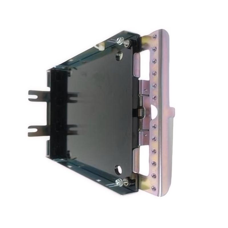
- GE
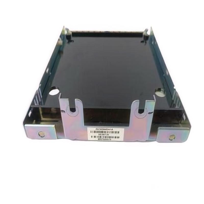
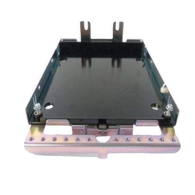
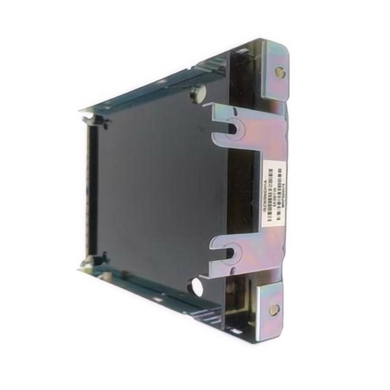
- IS230SNTCH4A
- Simplex Thermocouple Input Assembly
- USA
- 187 x 153 x 38 mm
- 0.4 kg
- Xiamen, China
- New & In Stock
- T/T, PayPal, Western Union
- 1 Year
- 1-3 Working Days
- DHL, UPS, TNT, FedEx and EMS.
- 24-Hour Service
- COO
- 5
Our advantage

Global Logistics
We have a 10-year logistics and express cooperation agreement, so our products can be shipped to any place in the world.

Brand new and original
Our products are imported in bulk from the place of origin. Because of the cooperative relationship, our products are all original and 100% new.

24-hour service
We provide 7*24 hours service to our customers. We will be there whenever you need us.

Price advantage
All our products are priced very favorably because we have our own warehouse and supply.
| Company Information | |||
| [email protected] | |||
| Mobile | +8615980777398 | ||
| +8615980777398 | |||
| 15980777398 |
Product Overview
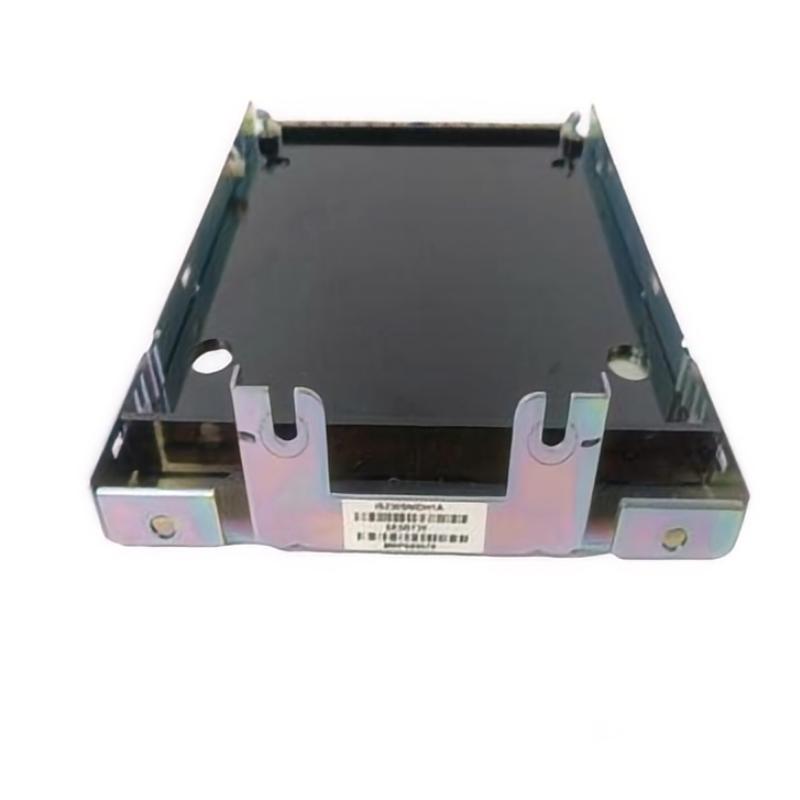
The GE IS230SNTCH4A Simplex Thermocouple Input Assembly is an industrial automation component designed for thermocouple-based temperature measurement in compatible GE control system configurations. Thermocouple input assemblies support the connection of temperature sensors to control hardware, allowing temperature-related signals to be incorporated into process monitoring, equipment supervision, and automated control strategies.
Temperature is a critical operating variable in many industrial environments. In gas turbine systems, power generation facilities, manufacturing processes, and other process industries, reliable temperature measurements help operators assess equipment conditions and identify deviations from normal operation. Thermocouples are widely used because they can measure temperature across a broad range of industrial conditions when paired with suitable input electronics and correctly installed wiring.
The IS230SNTCH4A is identified as a Simplex Thermocouple Input Assembly. Its general role is to provide an interface for thermocouple-related input signals within a compatible control architecture. The exact number of supported channels, thermocouple types, temperature ranges, accuracy, isolation characteristics, and system compatibility must be verified against the applicable hardware documentation.
With listed dimensions of 187 × 153 × 38 mm and a weight of approximately 0.4 kg, the assembly can be assessed for physical fit, cabinet layout, and replacement planning in industrial control installations.
Technical Specifications
| Parameter | Specification |
|---|---|
| Manufacturer | General Electric (GE) |
| Model | IS230SNTCH4A |
| Product Type | Simplex Thermocouple Input Assembly |
| Product Family | GE IS230 Series |
| Primary Function | Thermocouple temperature-signal input interface |
| Measurement Category | Temperature |
| Sensor Type | Thermocouple, subject to compatible system configuration |
| Control Architecture | Compatible GE industrial control system |
| Dimensions | 187 × 153 × 38 mm |
| Weight | 0.4 kg |
| Installation | Compatible industrial control assembly |
| Channel Capacity | Verify against the applicable hardware documentation |
| Supported Thermocouple Types | Verify against the applicable hardware documentation |
Note: Input ranges, thermocouple types, channel count, accuracy, cold-junction compensation method, terminal assignments, and electrical isolation specifications should be confirmed for the exact hardware revision.
Understanding Thermocouple Input Technology
A thermocouple measures temperature using the electrical voltage generated by the junction of two dissimilar conductive materials. This voltage changes with the temperature difference between the measurement junction and the reference junction.
Because thermocouple signals are generally small, the associated input electronics must be designed to handle the expected signal range and account for the relevant measurement conditions. Correct sensor selection, wiring, reference-junction compensation, and configuration all contribute to reliable temperature measurement.
A typical measurement path can be represented as:
Process Temperature → Thermocouple Sensor → Thermocouple Wiring → IS230SNTCH4A Assembly → Compatible Control Electronics → Temperature Value
The exact signal path depends on the installed GE system architecture. The assembly should be used only with thermocouple sensors, wiring arrangements, and associated electronics confirmed to be compatible.
Function and Working Principle
1. Temperature Signal Acquisition
A thermocouple generates a small electrical signal associated with the temperature difference between its measurement junction and reference junction. The compatible input system receives this signal through the designated sensor connections.
The IS230SNTCH4A is identified as a thermocouple input assembly, making temperature-signal interfacing its stated application. Specific sensor types and input characteristics must be confirmed before the assembly is connected to field wiring.
2. Signal Conditioning and Measurement Processing
Thermocouple signals can be affected by electrical noise, wiring resistance, connection quality, and environmental conditions. Thermocouple input electronics are generally designed to acquire and process these signals so that the control system can interpret the measured temperature.
The exact signal-conditioning functions implemented by the IS230SNTCH4A should not be assumed without the relevant technical documentation. In particular, its internal conversion method and measurement performance should be verified for the installed configuration.
3. Reference-Junction Compensation
Thermocouple measurements depend on the temperature difference between the measurement junction and the reference junction. Accurate measurement therefore requires an appropriate reference-junction compensation method.
The method used in the IS230SNTCH4A installation must be confirmed from the associated system documentation. Correct configuration and installation are important because compensation errors can produce a systematic temperature offset.
4. Communication With the Control System
After the temperature signal has been acquired and processed by the appropriate electronics, the resulting measurement can be used by the control system for monitoring, alarm evaluation, data recording, or control logic.
The assembly’s exact connection to the controller depends on the host platform and its configured hardware architecture.
Role in Industrial Automation
Temperature monitoring is important for both process control and equipment condition assessment. A thermocouple input assembly helps bring temperature-related information from the field into a compatible automation system.
Within an industrial control architecture, the assembly can form part of a measurement chain that includes the sensor, thermocouple extension wiring, input hardware, controller, and operator interface.
Typical system-level uses of thermocouple input technology include:
- Monitoring process and equipment temperatures.
- Providing temperature values to control logic.
- Supporting configured high- and low-temperature alarms.
- Recording temperature trends for operational review.
- Helping operators identify abnormal thermal conditions.
- Supporting automated process responses where the control strategy requires temperature feedback.
The exact role of the IS230SNTCH4A depends on its approved application and the functions assigned to the complete control system.
Industrial Applications
Gas Turbine Temperature Monitoring
Gas turbine installations rely on temperature information for monitoring operating conditions and supporting control and protection strategies. Thermocouple technology is commonly used in high-temperature industrial measurement applications.
The suitability of the IS230SNTCH4A for a particular turbine measurement point must be confirmed using the relevant GE system documentation.
Power Generation
Power generation facilities monitor temperatures in equipment and auxiliary processes to support operating supervision and maintenance. Thermocouple input assemblies can form part of the instrumentation system where the sensor and control platform are compatible.
Industrial Process Manufacturing
Chemical processing, material production, and other industrial operations may require continuous temperature monitoring. Thermocouple signals can be integrated into control systems to provide process feedback and support temperature-related alarms.
Heating and Thermal Equipment
Industrial furnaces, heaters, and thermal processing systems use temperature sensors to observe and regulate operating conditions. A suitable thermocouple input interface can connect these sensors to compatible control hardware.
General Industrial Instrumentation
Thermocouples are used in a wide range of industrial applications because they can support temperature measurement under varied operating conditions. Reliable performance depends on selecting the correct sensor type, installation method, and input configuration.
These examples describe common thermocouple measurement applications. They do not confirm that every application or sensor type is supported by the IS230SNTCH4A.
Installation and System Integration
Correct installation helps preserve measurement accuracy and reduce avoidable signal faults. The assembly should be installed only in the intended GE control configuration.
1. Verify the Model and Revision
Confirm the complete model designation IS230SNTCH4A, available revision markings, and the assembly’s intended location within the control system.
Compare the replacement with the original component and the applicable hardware records. Similar-looking assemblies may have different input characteristics or wiring requirements.
2. Confirm Thermocouple Compatibility
Identify the installed thermocouple type and verify that it is supported by the associated input hardware and configuration.
Thermocouple types use different material combinations and have different temperature-voltage relationships. An incorrect type selection or configuration can produce inaccurate readings even when the wiring appears correct.
3. Check Polarity and Wiring
Thermocouple wiring polarity must be correct. Reversed connections can cause abnormal readings or temperature changes that move in the wrong direction.
Use the approved wiring diagram to verify terminal assignments, extension-wire type, and connection polarity. Do not infer terminal numbers from the product model or physical appearance.
4. Review Grounding and Noise Control
Thermocouple signals are relatively small and can be affected by electrical interference. Cable routing, shielding, grounding, and separation from high-power conductors should follow the requirements of the installed control system.
Avoid introducing unapproved grounding connections or wiring modifications, as these may affect measurement quality or system safety.
5. Verify Reference-Junction Compensation
Confirm that the applicable reference-junction compensation method is correctly implemented and configured. Incorrect compensation can cause a consistent measurement offset.
The specific method should be determined from the documentation for the complete input assembly and control platform.
6. Commission the Temperature Measurement
After installation, verify the wiring, sensor configuration, and diagnostic status. Compare the displayed temperature with an appropriate reference or expected process condition when practical.
Where required, perform sensor and input-loop checks using approved test procedures. Confirm that temperature alarms and control responses behave as intended before returning the equipment to normal operation.
Troubleshooting the IS230SNTCH4A
Temperature measurement problems may originate in the thermocouple, extension wiring, terminal connections, input assembly, configuration, or associated control electronics. Troubleshooting should consider the entire measurement chain.
No Temperature Reading
If the controller does not display a valid temperature, inspect:
- Thermocouple condition and connection.
- Sensor cable and extension-wire continuity.
- Terminal assignments and polarity.
- Assembly seating and connector condition.
- Associated input hardware status.
- Sensor configuration and diagnostic messages.
- Relevant control-system power and interface connections.
A broken thermocouple or damaged cable can produce symptoms similar to an input hardware fault.
Reading Is Too High or Too Low
An incorrect temperature may be caused by the wrong thermocouple type, reversed polarity, incorrect reference-junction compensation, unsuitable extension wire, poor connections, or an input configuration problem.
Compare the configured sensor type with the actual installed sensor. Verify the measurement using an appropriate reference method before replacing the assembly.
Unstable Temperature Reading
Fluctuating values may result from loose connections, electrical interference, damaged wiring, poor shielding, a deteriorating sensor, or unstable process conditions.
Inspect the signal wiring and installation environment. If permitted by the maintenance procedure, compare the measurement at appropriate points in the signal chain to identify where the instability originates.
Temperature Changes in the Wrong Direction
Unexpected readings during heating or cooling may indicate reversed thermocouple polarity, incorrect wiring, a configuration mismatch, or a sensor fault.
Verify the positive and negative connections according to the specified thermocouple type and wiring diagram. Do not swap conductors without first confirming the correct configuration.
Persistent Measurement Offset
A persistent difference between the displayed temperature and an independent reference may indicate incorrect sensor selection, reference-junction compensation issues, unsuitable extension wiring, or a problem in the measurement electronics.
Use an approved test method to distinguish sensor-related errors from input-system errors.
Maintenance Recommendations
Regular inspection of the sensor and the associated input assembly can help maintain dependable temperature measurement.
Inspect sensor wiring: Look for damaged insulation, loose connections, corrosion, and mechanical strain.
Check thermocouple condition: Inspect the sensor for wear, contamination, or damage caused by its operating environment.
Maintain correct wire types: Ensure that thermocouple extension and compensation wires are appropriate for the installed sensor type and system requirements.
Review temperature trends: Investigate unusual offsets, unexpected fluctuations, or gradual changes that cannot be explained by normal process behavior.
Check configuration records: Maintain accurate records of the sensor type, input assignment, wiring arrangement, and applicable configuration settings.
Protect the control assembly: Keep the enclosure within the environmental limits specified for the installed equipment and protect connectors from contamination.
Document maintenance activities: Record recurring faults, sensor replacements, test results, and any changes made to the measurement configuration.
All testing and maintenance should follow the approved procedures for the host control platform and operating process.
Compatible System Components
The IS230SNTCH4A should be integrated only with components confirmed to be compatible with the intended GE control system. A typical thermocouple measurement arrangement may include:
| Component | General Function |
|---|---|
| GE IS230SNTCH4A | Thermocouple input assembly identified for the application |
| Thermocouple Sensor | Produces a temperature-dependent electrical signal |
| Thermocouple Extension Wire | Carries the sensor signal to the control assembly |
| Compatible Input Electronics | Acquires and processes the thermocouple signal |
| Control Processor | Uses the temperature measurement in control logic |
| Operator Interface | Displays temperature values and configured alarms |
| Engineering and Diagnostic Tools | Support configuration checks and fault analysis |
This table describes the functional elements of a typical thermocouple measurement chain. Exact companion module numbers, channel assignments, and approved sensor combinations must be confirmed for the installed system.
Replacement and Procurement Considerations
When sourcing a replacement GE IS230SNTCH4A Simplex Thermocouple Input Assembly, verify the complete part number and its intended role within the host control architecture.
Important checks include:
- Full model designation and revision.
- Original installation location.
- Supported thermocouple types.
- Input channel capacity and electrical characteristics.
- Terminal arrangement and wiring polarity.
- Reference-junction compensation requirements.
- Compatibility with associated GE control hardware.
- Required configuration and commissioning procedures.
The listed dimensions are 187 × 153 × 38 mm, and the listed weight is 0.4 kg. These details are useful for inventory management, cabinet planning, and replacement logistics.
A component should not be selected solely because its physical dimensions are similar to those of the original assembly. Thermocouple input hardware can differ in sensor compatibility, wiring, and measurement characteristics, so the exact hardware configuration must be verified before substitution.
Technical FAQs
What is the GE IS230SNTCH4A?
The GE IS230SNTCH4A is identified as a Simplex Thermocouple Input Assembly designed for temperature-signal interfacing in a compatible industrial control system.
What is a thermocouple input assembly used for?
It supports the connection and acquisition of thermocouple-related signals so that temperature information can be used by the associated control system.
What types of thermocouples does the IS230SNTCH4A support?
The supported sensor types should be verified using the applicable hardware documentation. They should not be inferred from the model designation alone.
What are the dimensions of the IS230SNTCH4A?
The listed dimensions are 187 × 153 × 38 mm.
How much does the IS230SNTCH4A weigh?
The listed weight is approximately 0.4 kg.
Why is thermocouple polarity important?
Reversed polarity can cause unexpected temperature readings, including a measurement that changes in the wrong direction as the process temperature changes.
What can cause an inaccurate temperature reading?
Possible causes include sensor damage, incorrect thermocouple type selection, wiring errors, electrical interference, reference-junction compensation problems, and faults in the associated input electronics.
Can another GE input assembly replace the IS230SNTCH4A?
Not automatically. The complete part number, revision, supported thermocouple type, input characteristics, wiring arrangement, and host-system compatibility should be confirmed before replacement.
Conclusion
The GE IS230SNTCH4A Simplex Thermocouple Input Assembly is an industrial control component identified for thermocouple-based temperature measurement in compatible GE automation systems. By supporting the connection of temperature sensors to the control architecture, it can contribute to process monitoring, equipment supervision, and temperature-related control strategies.
With listed dimensions of 187 × 153 × 38 mm and a weight of 0.4 kg, the assembly can be evaluated for physical fit and replacement planning. Reliable operation depends on correct sensor selection, accurate wiring, appropriate reference-junction compensation, compatible input hardware, and thorough commissioning.
For procurement and maintenance, verify the complete IS230SNTCH4A designation and the requirements of the installed control system before replacement. Careful wiring inspection, systematic troubleshooting, and accurate configuration records help maintain dependable temperature measurement and stable industrial control operation.