

ProductPRODUCT
Featured products
Contact Us
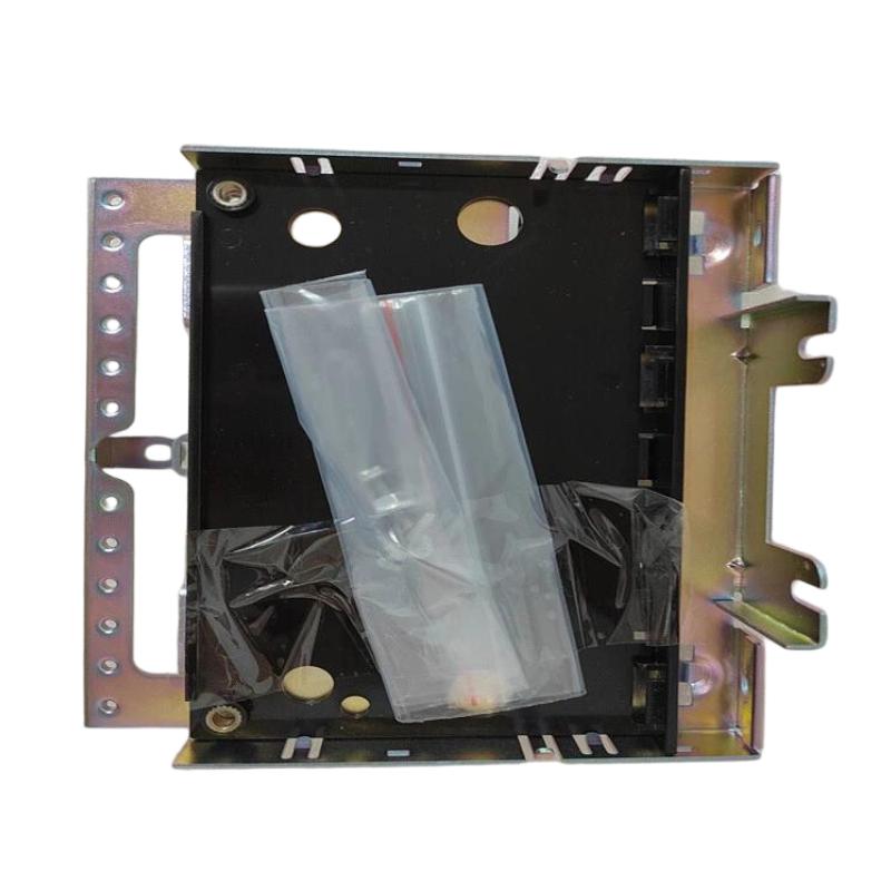
- GE
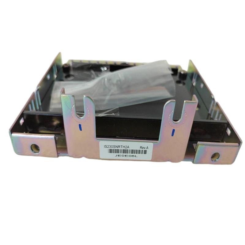
- IS230SNRTH2A
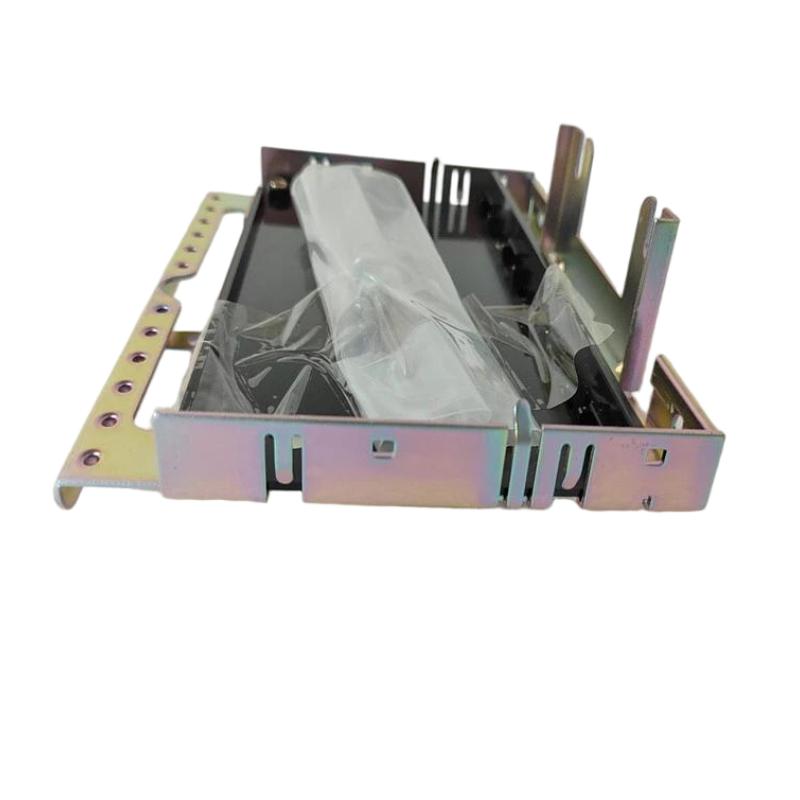
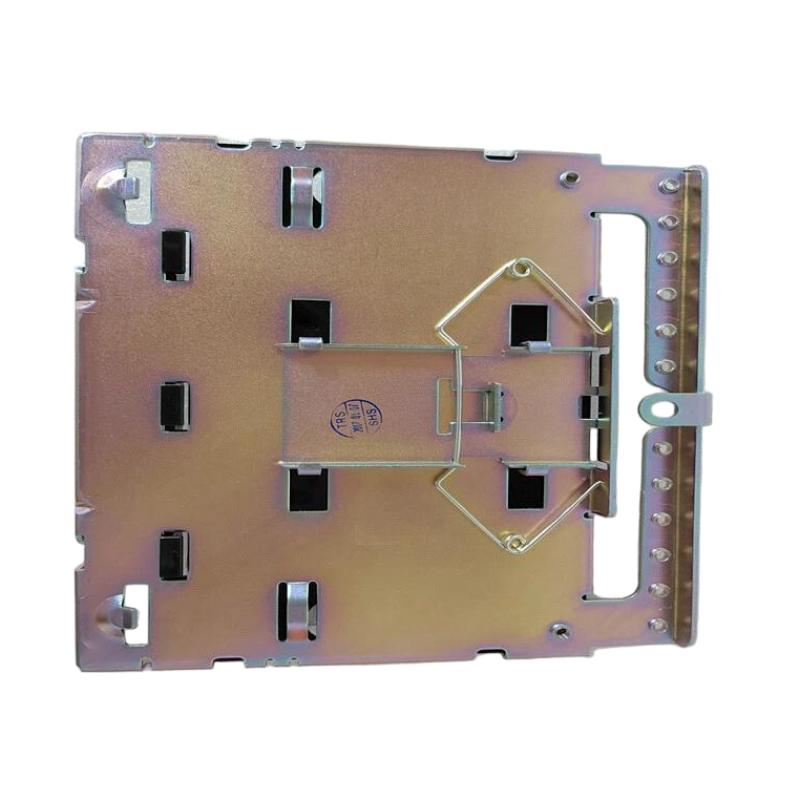
- Gas Turbine Module Base
- USA
- 167 × 148 × 55 mm
- 0.6 kg
- Xiamen, China
- New & In Stock
- T/T, PayPal, Western Union
- 1 Year
- 1-3 Working Days
- DHL, UPS, TNT, FedEx and EMS.
- 24-Hour Service
- COO
- 5
Our advantage

Global Logistics
We have a 10-year logistics and express cooperation agreement, so our products can be shipped to any place in the world.

Brand new and original
Our products are imported in bulk from the place of origin. Because of the cooperative relationship, our products are all original and 100% new.

24-hour service
We provide 7*24 hours service to our customers. We will be there whenever you need us.

Price advantage
All our products are priced very favorably because we have our own warehouse and supply.
| Company Information | |||
| [email protected] | |||
| Mobile | +8615980777398 | ||
| +8615980777398 | |||
| 15980777398 |
Product Overview
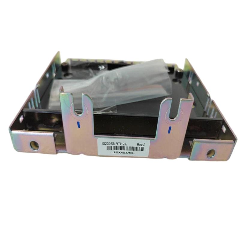
The GE IS230SNRTH2A Gas Turbine Module Base is an industrial control hardware component identified for use in compatible GE gas turbine automation systems. Module bases provide a physical and electrical foundation for integrating control-related hardware into an organized system architecture. Depending on the specific assembly design, a module base may support component mounting, electrical interconnection, and the arrangement of associated modules within a control cabinet or equipment enclosure.
Gas turbine control systems coordinate multiple functions associated with turbine operation, monitoring, protection, and auxiliary equipment. These systems rely on properly installed electronic assemblies and reliable interconnections to support communication between control hardware and the wider automation architecture. A correctly matched module base helps maintain the intended mechanical arrangement and provides the foundation required for the associated components.
The IS230SNRTH2A is identified as a Gas Turbine Module Base. Its exact electrical role, supported modules, connector configuration, and position within a specific GE control system should be verified against the installed equipment and applicable hardware documentation. The model designation alone does not establish its detailed pin assignments or interchangeability with other module bases.
With listed dimensions of 167 × 148 × 55 mm and a weight of approximately 0.6 kg, the IS230SNRTH2A can be evaluated for physical fit, replacement planning, and spare-parts inventory in compatible industrial control installations.
Technical Specifications
| Parameter | Specification |
|---|---|
| Manufacturer | General Electric (GE) |
| Model | IS230SNRTH2A |
| Product Type | Gas Turbine Module Base |
| Product Family | GE IS230 Series |
| Primary Role | Module mounting and system integration base |
| Application Area | Gas turbine control and industrial automation |
| Installation Environment | Compatible industrial control assembly |
| Dimensions | 167 × 148 × 55 mm |
| Weight | 0.6 kg |
| Electrical Interface | Confirm against the applicable hardware documentation |
| Compatible Modules | Verify according to the host-system configuration |
Note: Connector layout, pin assignments, electrical ratings, supported module types, and exact system compatibility must be confirmed for the specific hardware revision.
Understanding the GE IS230SNRTH2A Module Base
A module base is different from a controller, input/output module, or signal-processing board. Its primary purpose is to provide the mechanical and, where designed, electrical interface required to install associated hardware within a control system.
In an industrial turbine-control environment, electronic modules may be arranged in dedicated assemblies to support monitoring, control, communication, or protection functions. The module base helps establish the physical relationship between the installed component and the wider control architecture.
The general relationship can be represented as:
Control Cabinet → Module Base → Compatible Electronic Assembly → Control System Interconnection
The actual arrangement for the IS230SNRTH2A depends on the GE platform and the equipment in which it is installed. Its precise role should be determined from the system’s assembly drawings, component labels, and approved configuration records.
Function and Working Principle
1. Mechanical Support
A module base provides a mounting foundation for the hardware designed to fit it. Proper mechanical support helps keep the assembly securely positioned and reduces the risk of movement caused by vibration or routine equipment handling.
The listed dimensions of 167 × 148 × 55 mm can help technicians assess whether the component fits the intended mounting location. Physical measurements should be compared with the original assembly before replacement.
2. Hardware Integration
Depending on its design, a module base may provide the mechanical alignment and connector interface needed to integrate an associated electronic module into the control system.
The exact connection arrangement for the IS230SNRTH2A should not be inferred from its external appearance. Connector type, contact arrangement, and compatible hardware must be verified using the applicable documentation.
3. Electrical Interconnection
Some module bases provide electrical connections between the installed hardware and other parts of the control system. Where this applies, correct mating and alignment are important for maintaining the intended electrical path.
The specific electrical functions of the IS230SNRTH2A should be confirmed before installation. It should not be assumed to perform signal acquisition, output generation, or control processing unless those functions are explicitly assigned to the associated assembly.
4. Support for System Maintenance
A properly identified and installed module base helps technicians maintain the intended hardware arrangement. Correct component identification and documented installation procedures can simplify inspection, replacement, and troubleshooting.
This is particularly important in turbine-control systems, where incorrect component substitution may affect system availability or require additional commissioning work.
Role in Gas Turbine Control Systems
Gas turbine control systems combine hardware and software to manage operating conditions, monitor equipment status, coordinate auxiliary systems, and respond to abnormal conditions. Different assemblies perform distinct roles within this architecture.
A module base contributes at the hardware-integration level. It provides the mounting and interconnection arrangement required for the compatible component rather than replacing the functions of the control processor or associated electronic module.
Depending on the overall system design, the wider assembly may support functions such as:
- Turbine operating-condition monitoring.
- Control-system hardware integration.
- Communication between electronic assemblies.
- Installation and replacement of designated modules.
- Organization of hardware within the control cabinet.
- Maintenance of the intended system configuration.
These are general functions of gas turbine control architectures. The specific functions associated with the IS230SNRTH2A depend on its verified installation and compatible hardware.
Industrial Applications
Gas Turbine Control Equipment
Gas turbine installations use dedicated control hardware to coordinate turbine operation and associated systems. A compatible module base can provide the mounting or interconnection foundation for the designated assembly.
Power Generation Facilities
Power plants depend on organized control cabinets and reliable electronic hardware integration. Module bases can contribute to the physical structure of the control system and support maintenance activities.
Industrial Turbine Installations
Gas turbines are also used in industrial applications requiring mechanical power or on-site energy generation. The module base may be used within an approved control configuration where the relevant GE hardware is installed.
Turbine Auxiliary Systems
Turbine installations include auxiliary equipment and monitoring systems that support normal operation. The specific application of the IS230SNRTH2A within an auxiliary or primary control assembly should be confirmed from the equipment documentation.
These examples describe potential application environments for turbine-control hardware and do not independently verify every installation supported by this specific model.
Installation and System Integration
Installation should be performed by qualified personnel following the procedures established for the host GE control system. Because a module base may include mechanical and electrical interfaces, incorrect installation can affect the fit or connection of associated hardware.
1. Verify the Model Number
Confirm the complete designation IS230SNRTH2A, available revision markings, and the identification of the original assembly.
Compare the replacement with the installed part and the system’s component records. Similar dimensions or a similar product name do not guarantee compatibility.
2. Confirm the Associated Hardware
Identify the electronic module or assembly intended to fit the base. Verify the applicable part numbers, revision requirements, connector arrangement, and mounting configuration before proceeding.
Do not install a module solely because it appears to fit mechanically.
3. Follow Electrical Safety Procedures
Before removing or installing the module base, follow the site’s approved isolation and lockout/tagout procedures. Confirm that the relevant equipment is in a safe state and comply with any turbine-specific maintenance requirements.
Where the work could affect turbine availability or protection functions, follow the applicable outage planning and change-control procedures.
4. Inspect the Mounting Location
Check the mounting surface, retaining features, connectors, and surrounding hardware for damage, contamination, corrosion, or mechanical distortion.
The listed dimensions are 167 × 148 × 55 mm, and the listed weight is 0.6 kg. Confirm adequate space for the base, mating components, wiring, and maintenance access.
5. Check Connectors and Alignment
Before mating the associated hardware, inspect the connection interfaces for bent contacts, foreign material, damaged guides, or other visible defects.
Align components according to the approved procedure. Avoid forcing a connector or using excessive mechanical pressure to compensate for incorrect positioning.
6. Complete Post-Installation Checks
After installation, verify that the base and associated module are properly seated and secured. Check the assembly against the system drawings and confirm that the control system reports the expected hardware status.
Any required functional tests should be completed under the approved commissioning procedure before the equipment is returned to service.
Troubleshooting the IS230SNRTH2A
Problems involving a module base may appear as mechanical fit issues, connector problems, or faults associated with the installed electronic assembly. Troubleshooting should distinguish between a base-related issue and a fault originating in the connected module or wider control system.
Module Does Not Seat Correctly
If the associated module does not fit securely, inspect:
- Correct base model and revision.
- Mechanical alignment and mounting position.
- Retaining features and guides.
- Connector condition.
- Signs of deformation or physical damage.
- Compatibility of the associated module.
Do not force the components together. Confirm the approved assembly combination before continuing.
Intermittent Hardware Connection
Intermittent faults may be associated with loose seating, damaged contacts, vibration, contamination, or a problem in the connected module.
Inspect the assembly under approved safe-work conditions and review the control system’s diagnostic information. Where permitted, compare the behavior with the maintenance history to determine whether the fault is recurring.
Control System Reports a Hardware Fault
A hardware alarm does not automatically indicate that the module base has failed. The cause may be associated with the electronic module, connector interface, power supply, configuration, or another part of the system.
Record the diagnostic message and verify the installed hardware against the approved configuration. Follow the platform-specific diagnostic procedure before replacing components.
Visible Damage or Corrosion
Cracked mounting features, damaged connectors, corrosion, or other physical defects may affect the reliability of the assembly. Remove the component from service only in accordance with the relevant maintenance procedure and replace it with a verified compatible part when necessary.
Maintenance Recommendations
Routine inspection and accurate maintenance records can help preserve the integrity of the module assembly.
Inspect the physical condition: Look for cracks, deformation, corrosion, contamination, or damage to the mounting and connection features.
Check component seating: Confirm that the associated hardware is properly aligned and secured according to the approved procedure.
Protect connector interfaces: Prevent foreign material from entering connection points and handle the assembly carefully during maintenance.
Maintain environmental conditions: Keep the control cabinet within the environmental limits specified for the installed equipment.
Document component identification: Record the model, revision, installation location, replacement date, and any associated diagnostic findings.
Verify the complete assembly: When a hardware fault occurs, inspect the base, connected module, power and interface connections, and system configuration rather than assuming that the base is the source of the problem.
All inspection and testing should follow the maintenance requirements for the specific GE control platform.
Compatible System Components
The IS230SNRTH2A should be used only with components verified for the intended system configuration. A typical turbine-control hardware arrangement may include the following functional elements.
| Component | General Function |
|---|---|
| GE IS230SNRTH2A | Module base identified for the gas turbine control application |
| Compatible Electronic Module | Performs the function assigned to the installed assembly |
| Control Processor | Executes control logic and manages system operation |
| Input/Output Hardware | Interfaces with supported field signals |
| Communication Interfaces | Support data exchange where required by the system design |
| Power Supply | Provides power to components that require it |
| Control Cabinet | Houses and protects the installed hardware |
| Engineering and Diagnostic Tools | Support configuration, status checks, and maintenance |
This table describes common elements of an industrial control architecture, not a verified list of specific modules compatible with the IS230SNRTH2A. Exact companion part numbers must be confirmed before procurement or installation.
Replacement and Procurement Considerations
When purchasing a replacement GE IS230SNRTH2A Gas Turbine Module Base, verify the exact part number and the intended system application.
Important checks include:
- Complete model designation and revision.
- Original installation location.
- Associated electronic module.
- Mechanical mounting arrangement.
- Connector type and interface configuration.
- Compatibility with the host GE control system.
- Physical condition of the original assembly.
- Required installation and commissioning procedures.
The listed dimensions are 167 × 148 × 55 mm, and the listed weight is 0.6 kg. These measurements can support cabinet planning, stock management, and replacement logistics.
Because industrial control components may share similar physical characteristics while serving different purposes, dimensional similarity alone should never be used to establish electrical or functional compatibility.
Technical FAQs
What is the GE IS230SNRTH2A?
The GE IS230SNRTH2A is identified as a Gas Turbine Module Base for a compatible industrial control installation.
What is the purpose of a module base?
A module base provides a physical mounting foundation and, depending on its design, an interface for connecting compatible electronic hardware to the wider control assembly.
Is the IS230SNRTH2A a turbine controller?
It is identified as a module base rather than a general-purpose controller. The control functions are performed by the associated electronic hardware and system configuration.
What are the dimensions of the IS230SNRTH2A?
The listed dimensions are 167 × 148 × 55 mm.
How much does the IS230SNRTH2A weigh?
The listed weight is approximately 0.6 kg.
Can another GE IS230-series base replace it?
Not automatically. The complete part number, revision, mounting arrangement, connector configuration, and supported hardware must be verified before substitution.
What should be checked if the installed module reports a fault?
Inspect the seating and connector condition, verify the associated module and system configuration, and review the control system’s diagnostic information. A fault should not be attributed to the base without appropriate checks.
Does the module base perform signal processing?
Its primary identification is that of a module base. Any signal-processing or control function should be attributed to the associated electronics only when confirmed by the applicable hardware documentation.
Conclusion
The GE IS230SNRTH2A Gas Turbine Module Base is an industrial control hardware component intended to support the mounting and integration of compatible equipment in a GE turbine-control environment. Correct mechanical alignment, verified hardware compatibility, and reliable connector interfaces are essential for maintaining the integrity of the installed assembly.
With listed dimensions of 167 × 148 × 55 mm and a weight of 0.6 kg, the component can be evaluated for physical fit and replacement planning. Successful integration depends on confirming the full model designation, identifying the associated module, following approved installation procedures, and completing the necessary post-installation checks.
For replacement and maintenance work, verify the IS230SNRTH2A identification and the intended hardware combination before installation. Careful inspection, accurate component records, and systematic troubleshooting help support reliable industrial control equipment and long-term maintainability.