
NewsNEWCENTER
Featured products
Contact Us
GE IS200TBC1H1BCE Mark VI Contact Terminal Board Troubleshooting Guide
2026-09-17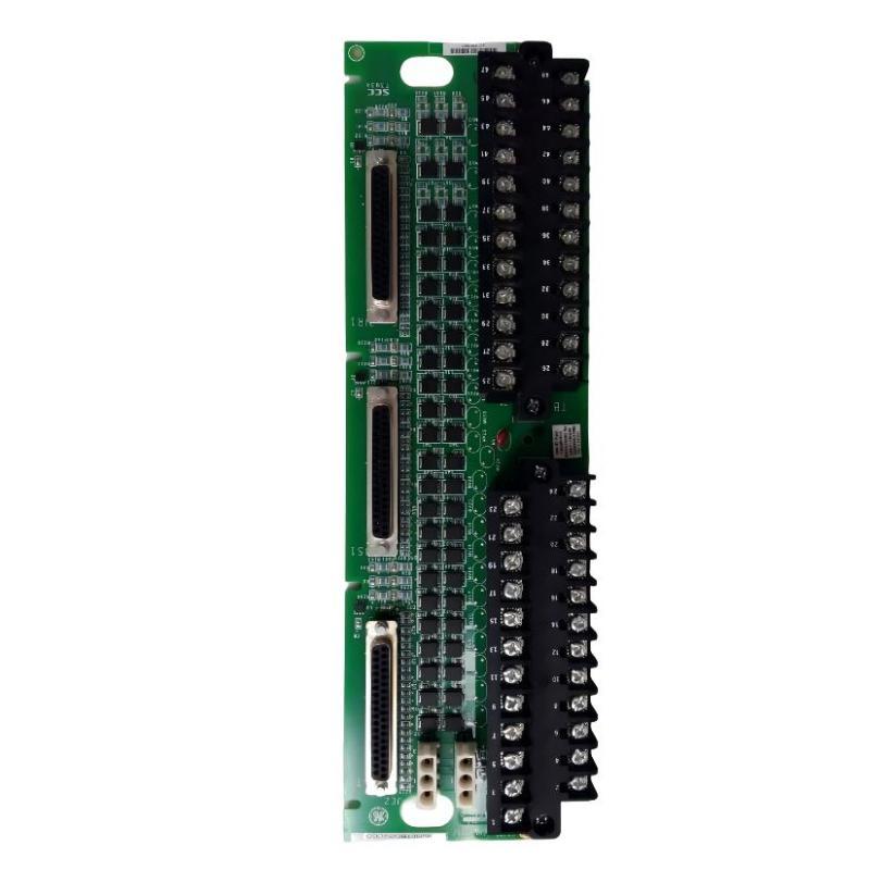
Table of Contents
- GE IS200TBC1H1BCE Fault Diagnosis Overview
- GE IS200TBC1H1BCE Common Fault Symptoms
- Common Causes of GE IS200TBC1H1BCE Faults
- GE IS200TBC1H1BCE Troubleshooting Diagnostic Logic
- GE IS200TBC1H1BCE Signal Testing and Fault Analysis
- GE IS200TBC1H1BCE Repair and Replacement Procedure
- GE IS200TBC1H1BCE Field Troubleshooting Case
- GE IS200TBC1H1BCE Troubleshooting FAQ
- GE IS200TBC1H1BCE Technical Summary
GE IS200TBC1H1BCE Mark VI Fault Diagnosis Overview
The GE IS200TBC1H1BCE sits within the field-signal interface of a Mark VI control system. As a result, troubleshooting should not automatically identify the terminal board as the source of an I/O problem. A reliable diagnosis separates the field device, field cable, terminal interface, I/O electronics, and controller configuration into individual sections.
The basic diagnostic principle is simple: determine where a signal changes from normal to abnormal.
Field Device
     |
     v
Field Wiring
     |
     v
IS200TBC1H1BCE
     |
     v
Mark VI I/O
     |
     v
Controller
     |
     v
HMI / Control Logic
If the field device is producing a valid signal but the controller receives an incorrect state, the investigation can progressively move through each interface until the fault location is isolated.
GE IS200TBC1H1BCE Common Fault Symptoms
Potential symptoms associated with the IS200TBC1H1BCE interface include:
- One or more field contact indications are incorrect.
- Digital input status changes intermittently.
- Several related signals disappear simultaneously.
- An I/O diagnostic appears after cabinet maintenance.
- A field signal is correct locally but incorrect in the Mark VI controller.
- Control logic responds to an incorrect contact state.
- Alarm or permissive conditions appear unexpectedly.
- Signals change when a cable or connector is physically disturbed.
- A replacement terminal board does not eliminate the original symptom.
These symptoms should be treated as diagnostic clues rather than proof of terminal-board failure.
Common Causes of GE IS200TBC1H1BCE Faults
Loose Field Termination
A loose conductor can create intermittent contact behavior, especially in equipment exposed to vibration or repeated thermal cycling.
Incorrect Wiring
A conductor installed on the wrong terminal can create a persistent but misleading signal fault. This is particularly common after replacement work when field labels are unclear.
Damaged Cable or Connector
Broken conductors, damaged insulation, corroded contacts, or mechanically damaged connectors can interrupt the signal between the field device and I/O system.
Field Device Failure
A faulty switch, sensor, relay contact, or actuator interface may produce an abnormal signal even when the terminal board is operating correctly.
I/O or Controller Problem
The Mark VI I/O interface or controller configuration can also be responsible. A terminal-board investigation should therefore include the receiving I/O channel.
Terminal Board Failure
If field wiring and the connected device are verified, while the signal path through the IS200TBC1H1BCE remains abnormal, the board itself becomes a stronger candidate for replacement or further technical evaluation.
GE IS200TBC1H1BCE Troubleshooting Diagnostic Logic
The following diagnostic sequence can be adapted to the actual Mark VI system:
Reported Field Signal Fault
          |
          v
Check Mark VI Diagnostic Information
          |
          v
Check Field Device
          |
     +----+----+
     |         |
   Normal   Abnormal
     |         |
     v         v
Check Wiring  Repair / Test
     |
     v
Check IS200TBC1H1BCE Terminals
     |
     v
Check I/O Interface
     |
     v
Compare Controller Signal
     |
     v
Identify Root Cause
When several signals fail together, give particular attention to common connections, shared wiring, common power, connectors, and the terminal-board interface.
GE IS200TBC1H1BCE Signal Testing and Fault Analysis
Testing should be performed with appropriate electrical instruments and according to the plant’s safety procedures. For critical control, protection, or trip circuits, technicians should use the approved test procedure and avoid creating unintended control commands.
Practical Test Sequence
- Record the exact alarm or abnormal signal.
- Determine whether the fault is continuous or intermittent.
- Review recent maintenance activity.
- Check the physical condition of the terminal board.
- Inspect the affected wiring and connectors.
- Verify the field device at the source.
- Compare the signal at the terminal interface.
- Check the corresponding Mark VI I/O channel.
- Compare the physical signal with the controller indication.
- Repeat the test under the condition that originally produced the fault.
Illustrative Measurement Record
Condition:
Field contact verified at source

At terminal interface:
Signal present during initial test

Observed:
Controller indication intermittently changes

Further inspection:
Cable termination and connector condition checked

Diagnostic direction:
Investigate intermittent connection before replacing
the terminal board.
This is an illustrative troubleshooting example rather than a manufacturer-defined test specification. Actual electrical measurements and acceptable limits must come from the applicable Mark VI system documentation.
GE IS200TBC1H1BCE Repair and Replacement Procedure
When the troubleshooting process indicates that the IS200TBC1H1BCE may be defective, replacement should be performed systematically.
Step 1: Document the Existing Condition
Record alarms, affected signals, controller indications, recent maintenance history, and the operating condition in which the fault occurred.
Step 2: Isolate the Equipment
Follow the approved electrical isolation and lockout procedure before removing the board or disconnecting field wiring.
Step 3: Inspect Before Removal
Look for damaged connectors, loose mounting hardware, contamination, corrosion, abnormal heating, or damaged wiring. These observations can reveal the real cause of the fault.
Step 4: Verify the Replacement Board
Confirm the complete IS200TBC1H1BCE identification and applicable revision. Do not substitute a visually similar board without confirming system compatibility.
Step 5: Transfer and Verify Wiring
Reconnect conductors according to the approved drawings. Each terminal should be independently verified rather than transferred solely by physical position.
Step 6: Perform Controlled Testing
Restore the system following the approved startup procedure and check Mark VI diagnostics, field signals, I/O states, and control responses.
Step 7: Reproduce the Original Fault Condition
If possible, test the system under the same operating condition that originally produced the problem. This provides stronger evidence that the repair has resolved the root cause.
GE IS200TBC1H1BCE Field Troubleshooting Case
In a representative Mark VI troubleshooting case, several digital field indications intermittently changed state during equipment operation. The controller and I/O diagnostics did not immediately identify a failed electronic module.
The maintenance team compared the field-device states with the controller indications and discovered that the signals were correct at the field devices but unstable at the control-system interface. The investigation then focused on the common wiring path and terminal connections.
A mechanical inspection found a loose field termination. After the connection was corrected, the signals remained stable during repeated equipment cycles. The terminal board itself did not require replacement.
This example highlights an important fault-diagnosis rule: when the source signal is healthy but the controller indication is unstable, investigate the complete transmission path before condemning the terminal board.
GE IS200TBC1H1BCE Troubleshooting FAQ
What is the first thing to check when an IS200TBC1H1BCE signal is abnormal?
Start by identifying whether the abnormal signal exists at the field device itself. Then trace the signal through the wiring, terminal board, I/O interface, and controller.
Why can several field signals fail at the same time?
Multiple simultaneous failures can indicate a common interface, connector, wiring group, power source, I/O path, or configuration issue. The common elements should be investigated before replacing individual field devices.
How can I distinguish a wiring problem from a terminal-board problem?
Compare the signal at the field device, at the terminal interface, and at the receiving I/O channel. If the signal is correct before the terminal interface but abnormal after it, the interface and its connections deserve closer investigation.
Should an intermittent signal automatically lead to terminal-board replacement?
No. Intermittent signals are frequently associated with loose terminals, damaged conductors, connector problems, vibration, or field-device contacts. These possibilities should be checked first.
What should be recorded after troubleshooting?
Record the original symptom, affected signals, diagnostic information, inspection findings, measurements, corrective action, replacement board identification if applicable, and final functional-test results.
GE IS200TBC1H1BCE Technical Summary
The GE IS200TBC1H1BCE Mark VI Contact Terminal Board is part of the field-interface architecture connecting plant devices with the Mark VI control system. Troubleshooting requires a signal-path approach because field-device faults, wiring problems, connector issues, I/O problems, and terminal-board failures can produce similar symptoms.
The most reliable GE IS200TBC1H1BCE troubleshooting method is to trace the affected signal from its source toward the controller, compare the signal at each interface, and reproduce the original fault condition after corrective work. This approach helps maintenance teams identify the actual root cause and avoid unnecessary replacement of otherwise serviceable hardware.