
NewsNEWCENTER
Featured products
Contact Us
GE IS200TBC1H1BCE Mark VI Contact Terminal Board Installation Guide
2026-09-17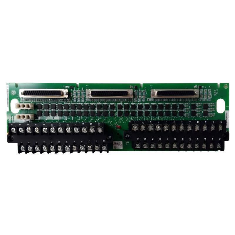
Table of Contents
- GE IS200TBC1H1BCE Installation Overview
- GE IS200TBC1H1BCE Function in the Mark VI System
- GE IS200TBC1H1BCE Installation Preparation
- GE IS200TBC1H1BCE Mounting and Cabinet Layout
- GE IS200TBC1H1BCE Wiring and Signal Integration
- GE IS200TBC1H1BCE Setup and Commissioning
- GE IS200TBC1H1BCE Installation Validation
- GE IS200TBC1H1BCE Field Commissioning Case
- GE IS200TBC1H1BCE Installation FAQ
- GE IS200TBC1H1BCE Technical Summary
GE IS200TBC1H1BCE Mark VI Contact Terminal Board Installation Overview
The IS200TBC1H1BCE is a GE Mark VI contact terminal board used as part of the control-system field interface. In a Mark VI installation, terminal boards help organize field connections between sensors, switches, actuators, protection circuits, and the associated control electronics.
Because terminal boards are directly associated with field wiring, installation errors can affect multiple signals simultaneously. A single incorrectly identified conductor, loose terminal, damaged connector, or poor shield connection may create symptoms that initially appear to be a controller, I/O, or field-device problem.
GE IS200TBC1H1BCE Function in the Mark VI System
The main role of the GE IS200TBC1H1BCE Mark VI Contact Terminal Board is to provide an organized electrical interface between field circuits and the Mark VI control architecture. The actual signal types and connection assignments depend on the specific system configuration and should be verified against the applicable engineering drawings.
A simplified Mark VI signal path can be represented as follows:
Field Sensors / Switches / Devices
              |
              v
     GE IS200TBC1H1BCE
       Contact Terminal Board
              |
              v
       Mark VI I/O Interface
              |
              v
       Mark VI Controller
              |
              v
   Control Logic / HMI / Plant Network
This architecture makes the terminal board an important troubleshooting and commissioning point. When several field signals behave abnormally at the same time, technicians should inspect the common interface before replacing individual field devices.
GE IS200TBC1H1BCE Installation Preparation
Good preparation is especially important when replacing an existing terminal board. Before removing the original board, record the existing wiring arrangement and compare it with the approved system drawings.
- Confirm the complete IS200TBC1H1BCE part number and applicable board revision.
- Verify compatibility with the installed Mark VI system configuration.
- Review the electrical schematic and terminal assignment documentation.
- Identify every connected field cable before disconnection.
- Record cable and terminal labels.
- Apply the required electrical isolation procedure.
- Check for stored electrical energy before handling wiring.
- Inspect the cabinet for dust, moisture, corrosion, or loose hardware.
- Inspect connectors and terminal interfaces for mechanical damage.
Photographs taken before removing the original board can provide useful maintenance evidence, but photographs should not replace engineering documentation. Previous field modifications may not be obvious from a visual inspection.
GE IS200TBC1H1BCE Mark VI Mounting and Cabinet Layout
The IS200TBC1H1BCE should be installed in its designated Mark VI cabinet position using the correct mounting hardware. The board should be mechanically stable while leaving sufficient space for wiring, connector access, inspection, and maintenance.
Mounting Checklist
- Confirm that the equipment is isolated according to the approved procedure.
- Inspect the mounting location.
- Check the replacement board for visible damage.
- Position the board correctly without forcing connectors or hardware.
- Secure the board using the designated mounting points.
- Check that field cables are not pulling against the terminal board.
- Maintain appropriate separation between signal wiring and noisy power conductors.
- Confirm that connectors and terminal interfaces remain accessible for inspection.
GE IS200TBC1H1BCE Wiring and Signal Integration
Correct wiring is the most important part of the IS200TBC1H1BCE installation process. The exact terminal assignments should always be confirmed from the documentation for the particular Mark VI configuration. Technicians should not assume that similarly named terminal boards have identical wiring.
A practical connection model is:
Field Device
     |
     | Field Cable
     v
+-------------------------+
| GE IS200TBC1H1BCE       |
| Mark VI Contact         |
| Terminal Board          |
+-------------------------+
     |
     | Interface Connection
     v
Mark VI I/O Electronics
     |
     v
Controller / Application Logic
Field Wiring Inspection
- Verify each conductor against the approved schematic.
- Check terminal identification before connecting wires.
- Inspect conductors for damaged insulation.
- Check terminal tightness according to the applicable installation procedure.
- Inspect connectors for bent, contaminated, or damaged contacts.
- Verify shield and drain-wire arrangements where applicable.
- Keep signal cables properly routed and supported.
- Separate sensitive signal wiring from high-energy switching circuits where required.
Do not use terminal position alone to identify an unknown wire. Markings, drawings, cable schedules, and system records should be used together to confirm the connection.
GE IS200TBC1H1BCE Setup and Commissioning
After mechanical installation and wiring, the Mark VI system should be commissioned progressively. The objective is to confirm that field signals reach the controller correctly before the equipment is returned to normal operating service.
Initial Commissioning Sequence
- Complete a visual inspection of the installed terminal board.
- Verify all connectors and field wiring.
- Confirm that no unused conductor can accidentally contact an adjacent terminal.
- Restore power according to the approved startup procedure.
- Check Mark VI controller and I/O diagnostics.
- Verify representative field inputs individually.
- Check associated outputs where applicable.
- Compare displayed values with field measurements.
- Perform functional testing of the affected control loop.
- Record commissioning results.
Commissioning Logic
Board Installed
      |
      v
Wiring Verification
      |
      v
System Power-Up
      |
      v
Mark VI Diagnostic Check
      |
      v
Verify Field Inputs
      |
      v
Verify Outputs / Commands
      |
      v
Functional Loop Test
      |
      v
Return to Service
GE IS200TBC1H1BCE Installation Validation
A complete installation validation should test the terminal board as part of the entire signal chain rather than checking only the physical board.
- Confirm that the Mark VI system starts without unexpected I/O diagnostics.
- Verify representative field signals.
- Compare controller values with local instrumentation where practical.
- Check digital contact states for correct open/closed behavior.
- Verify relevant output commands.
- Check for intermittent signals during equipment movement or vibration.
- Inspect terminal temperatures if abnormal resistance is suspected.
- Confirm that alarm and trip circuits respond according to the approved test procedure.
For critical control or protection signals, functional testing should follow the plant’s approved commissioning procedure rather than relying only on software indications.
GE IS200TBC1H1BCE Field Commissioning Case
In one representative Mark VI maintenance case, a terminal board was replaced after several field contact indications became intermittent. The Mark VI controller itself remained online, but operators observed occasional changes in several related status signals.
The commissioning team initially suspected multiple field switches. Instead of replacing the switches individually, the engineers traced the signals back toward the common interface. Inspection found that one field cable c