

ProductPRODUCT
Featured products



Contact Us


- GE
- IS200GGXIG1AFE
- Extended Load Source Board
- USA
- 220 × 140 × 35 mm
- 0.8 kg
- Xiamen, China
- New & In Stock
- T/T, PayPal, Western Union
- 1 Year
- 1-3 Working Days
- DHL, UPS, TNT, FedEx and EMS.
- 24-Hour Service
- COO
- 3
Our advantage

Global Logistics
We have a 10-year logistics and express cooperation agreement, so our products can be shipped to any place in the world.

Brand new and original
Our products are imported in bulk from the place of origin. Because of the cooperative relationship, our products are all original and 100% new.

24-hour service
We provide 7*24 hours service to our customers. We will be there whenever you need us.

Price advantage
All our products are priced very favorably because we have our own warehouse and supply.
| Company Information | |||
| [email protected] | |||
| Mobile | +8615980777398 | ||
| +8615980777398 | |||
| 15980777398 |
Product Overview
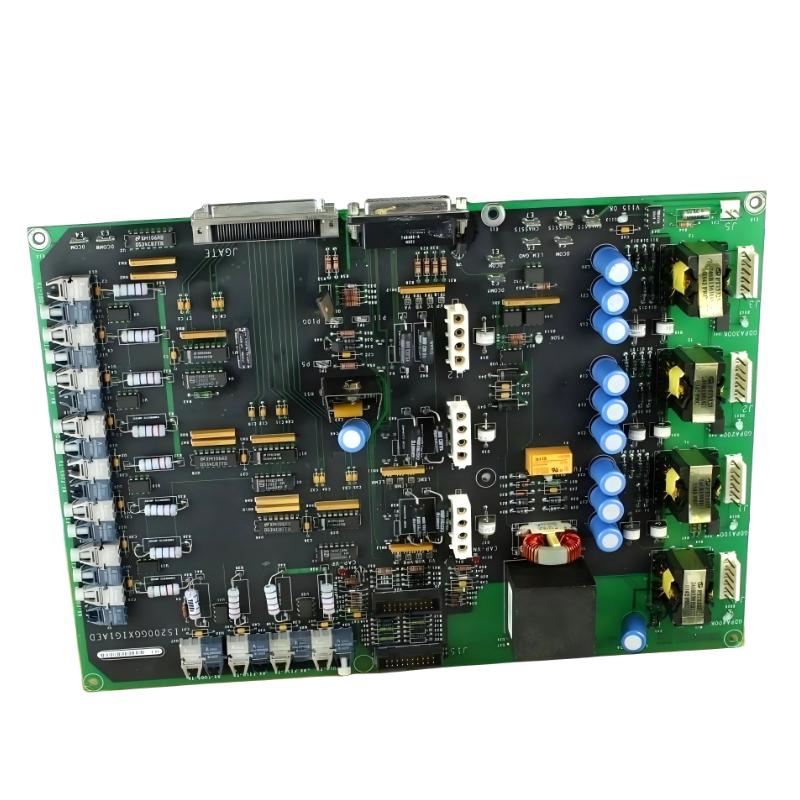
The GE IS200GGXIG1AFE Extended Load Source Board is a specialized industrial electronic component used within GE control and power-electronic equipment. As part of the IS200 series, the board is associated with electrical load-interface functions in systems where controlled power distribution and reliable signal or circuit connections are required.
The IS200GGXIG1AFE is designed to operate as part of a larger industrial control architecture rather than as an independent programmable controller. Its role is closely related to the electrical interface between control circuitry and the associated load or power circuit. Reliable connections, correct installation, and stable operating conditions are therefore essential for maintaining system performance.
The supplied dimensions of the board are 220 × 140 × 35 mm, with a weight of approximately 0.8 kg. This compact construction makes it suitable for installation within industrial control cabinets and specialized GE power-control assemblies where space, mechanical stability, and electrical reliability are important.
Technical Specifications
| Parameter | Specification |
|---|---|
| Manufacturer | GE |
| Model | IS200GGXIG1AFE |
| Product Type | Extended Load Source Board |
| Product Family | IS200 Series |
| Main Function | Load-source electrical interface |
| Application | Industrial control and power electronics |
| Dimensions | 220 × 140 × 35 mm |
| Weight | 0.8 kg |
| Installation | Industrial control / power assembly |
| System Role | Load and electrical interface |
| Application Environment | Industrial power-generation and control systems |
What Is the GE IS200GGXIG1AFE?
The GE IS200GGXIG1AFE is an Extended Load Source Board belonging to GE’s IS200 family of industrial control components.
The board is associated with the load-source portion of an electrical control architecture. In industrial power systems, different circuits require controlled electrical paths between power sources, switching elements, interface components, and loads. A dedicated source board can provide part of this physical and electrical interface.
Unlike a CPU or PLC processor, the IS200GGXIG1AFE should be understood primarily as a hardware-level component within a larger control or power assembly.
Its performance depends on the complete surrounding system, including associated wiring, power devices, terminal connections, protective components, cooling conditions, and control logic.
Understanding the Extended Load Source Function
Industrial power-control equipment often separates control signals from higher-energy electrical circuits.
The control system determines what action should occur, while interface and power components establish the appropriate electrical path.
A simplified architecture can be represented as:
Control Logic → Interface Circuit → Source / Load Circuit → Electrical Equipment
The IS200GGXIG1AFE can be positioned within this type of hardware architecture as part of the load-source interface.
The term Extended Load Source Board indicates that the board is associated with a source/load electrical function rather than being a general-purpose processing board.
This distinction is important during troubleshooting. A fault associated with the board may be caused by an upstream source, a downstream load, wiring, a connector, or another power-electronic component.
Role in Industrial Power-Control Systems
Industrial control equipment requires reliable electrical interfaces to ensure that commands and power are transferred correctly.
A source/load interface can support several important system requirements:
- Controlled electrical routing
- Reliable load connections
- Stable electrical contact
- Interface between control and power circuits
- Organized cabinet wiring
- Support for system switching functions
- Integration with other GE control hardware
The board itself forms only one part of the overall circuit.
A complete power-control system may include processors, signal-conditioning boards, relay drivers, semiconductor devices, terminal boards, feedback circuits, protective devices, and power supplies.
Correct coordination among these components is necessary for reliable operation.
Electrical Interface Considerations
Electrical interface components are often exposed to more demanding conditions than ordinary low-level signal boards.
Several factors influence their long-term reliability.
Electrical Load
The board and associated circuit should operate within the electrical limits established by the equipment design.
Unexpected overloads can increase thermal stress and accelerate component degradation.
Contact Resistance
A poor electrical connection can introduce additional resistance.
Even a relatively small increase in resistance can generate localized heating when significant current flows through the connection.
Transient Conditions
Industrial power equipment can experience switching transients and electrical disturbances. Proper system-level protection helps reduce stress on interface components.
Grounding
Appropriate grounding and bonding are essential for safe and stable operation of industrial electrical assemblies.
Thermal Management
The IS200GGXIG1AFE is installed in an environment where nearby electrical components may generate heat.
Thermal conditions should therefore be considered during maintenance.
Potential warning signs include:
- Discoloration
- Burn marks
- Melted insulation
- Unusual odor
- Damaged connectors
- Repeated thermal alarms
- Abnormal cabinet temperature
If excessive heat is discovered, replacing the board without identifying the source of the heat may result in repeated failure.
Possible causes can include excessive load, high contact resistance, poor ventilation, damaged components, or abnormal operating conditions.
Industrial Applications
Generator Control Systems
GE generator-control architectures may contain numerous interface and power components required for reliable operation of generator equipment.
Excitation Equipment
Excitation systems include control electronics and power circuits that must work together to regulate generator field conditions.
Power-Conversion Assemblies
Industrial power converters rely on electrical interfaces between control circuitry and higher-energy switching circuits.
Industrial Control Cabinets
The supplied 220 × 140 × 35 mm form factor allows the IS200GGXIG1AFE to be integrated into specialized cabinet assemblies.
Maintenance and Replacement
The board can be relevant when maintaining existing GE industrial equipment where an installed source/load interface component requires inspection or replacement.
Installation and System Integration
Installation should be performed by qualified industrial electrical or controls personnel.
Because the board may be integrated into power-related equipment, electrical isolation and safe discharge procedures must be completed before maintenance.
Confirm the Complete Model
Verify the complete identification:
GE IS200GGXIG1AFE
Do not rely only on the general description “Extended Load Source Board.” The full part number is essential for replacement planning.
Check the Mounting Location
The supplied dimensions are:
220 × 140 × 35 mm
Confirm that the replacement board has adequate mechanical clearance and that associated cables can be routed without excessive stress.
Inspect the Existing Installation
Before replacing the board, inspect:
- Mounting hardware
- Connectors
- Terminals
- Wiring
- Insulation
- Nearby components
- Signs of overheating
- Contamination
- Corrosion
Electrical Connection Inspection
A damaged connection can produce symptoms that resemble board failure.
Check for:
- Loose terminals
- Oxidized contacts
- Broken conductors
- Damaged insulation
- Heat discoloration
- Mechanical strain
Controlled Commissioning
After installation, verify the complete electrical path before returning the system to normal operation.
Check the board installation, connections, power conditions, associated loads, system diagnostics, and operating behavior.
Troubleshooting the GE IS200GGXIG1AFE
Troubleshooting should begin with the complete source-load circuit.
Load Does Not Operate
If an associated load does not respond as expected, inspect:
- The control command
- The upstream power source
- Board connections
- Output or load wiring
- Protective devices
- The load itself
- Related interface circuitry
This prevents unnecessary replacement of a functioning board.
Intermittent Load Operation
Intermittent behavior can be caused by:
- Loose connections
- Thermal expansion
- Vibration
- Contact degradation
- Unstable power
- Damaged wiring
- Aging electronic components
Observe whether the problem correlates with temperature, operating load, or machine vibration.
Excessive Heating
If the board or nearby connection becomes unusually hot, inspect the electrical path carefully.
Potential causes include:
- Excessive load
- High contact resistance
- Loose terminals
- Poor cooling
- Damaged components
- Abnormal current
Thermal inspection can help identify localized problems before permanent damage occurs.
Repeated Protection Alarms
If the system repeatedly generates electrical protection alarms, investigate the complete power circuit.
A source-board problem is only one possible cause. The associated load, switching device, control signal, wiring, and protective circuit should also be examined.
Common Failure Causes
Overload
Operating a circuit beyond its intended electrical conditions can generate excessive heat and accelerate component degradation.
Loose Connections
Loose electrical connections can produce voltage drops, unstable operation, and localized heating.
Thermal Stress
Repeated temperature cycling can gradually affect electronic components and connections.
Vibration
Long-term industrial vibration may loosen mounting hardware or contribute to connector degradation.
Moisture and Contamination
Humidity, dust, oil, and conductive contamination can reduce electrical insulation and accelerate corrosion.
Incorrect Installation
Incorrect wiring, mechanical misalignment, or improper replacement can create abnormal electrical stress.
Preventive Maintenance
Preventive maintenance helps reduce unexpected failures in industrial control equipment.
Recommended inspection activities include:
- Check the board for visible damage.
- Inspect electrical connections.
- Check for overheating.
- Monitor unusual load behavior.
- Inspect cabinet ventilation.
- Remove excessive dust and contamination.
- Check nearby wiring.
- Review system alarms.
- Record abnormal operating trends.
- Maintain accurate replacement records.
Maintenance should be performed according to the safety procedures established for the specific equipment.
Replacement Considerations
When replacing the GE IS200GGXIG1AFE, both mechanical and electrical compatibility should be verified.
| Verification Item | Requirement |
|---|---|
| Manufacturer | GE |
| Model | IS200GGXIG1AFE |
| Product Type | Extended Load Source Board |
| Dimensions | 220 × 140 × 35 mm |
| Weight | 0.8 kg |
| Application | Industrial control / power electronics |
| Mechanical Fit | Verify |
| Connector Configuration | Verify |
| Electrical Function | Verify |
| Board Revision | Check before installation |
| System Compatibility | Confirm before commissioning |
The physical dimensions supplied for the board are useful for cabinet planning, but they do not establish electrical compatibility.
A different GE IS200 component should not be substituted simply because it has a similar shape or mounting footprint.
Spare-Part Planning
For critical industrial equipment, maintaining a properly identified spare board can reduce downtime.
A useful spare-part record should include:
- Full part number
- Board revision
- Associated equipment
- Cabinet location
- Date received
- Storage condition
- Previous installation history
The replacement board should remain in protective packaging until required.
Handling and Storage
The supplied weight of the GE IS200GGXIG1AFE is 0.8 kg.
Although the board is relatively lightweight, its electronic circuitry should be protected from static electricity, moisture, and mechanical impact.
Recommended practices include:
- Use ESD-safe packaging.
- Handle the board carefully.
- Avoid touching exposed circuitry.
- Protect connectors.
- Keep the board dry.
- Avoid bending or impact.
- Store in a clean environment.
- Protect against conductive contamination.
Before installation, inspect the board for physical damage or corrosion.
Diagnostic Approach
When diagnosing a suspected IS200GGXIG1AFE problem, a structured process is more effective than immediate replacement.
Step 1: Identify the Symptom
Determine whether the problem is:
- Complete loss of load operation
- Intermittent operation
- Excessive heating
- Abnormal voltage
- Repeated alarm
- Unexpected switching behavior
Step 2: Check the External Circuit
Inspect power supply, wiring, terminals, connectors, and the associated load.
Step 3: Review System Diagnostics
Use available system alarms and operating records to identify whether the fault is isolated or part of a wider system problem.
Step 4: Inspect the Board
Look for visible damage, contamination, corrosion, or heat-related deterioration.
Step 5: Verify After Replacement
If replacement is necessary, verify all connections before controlled energization and commissioning.
This method helps avoid replacing a healthy board when the real fault is located elsewhere.
Key Advantages
The GE IS200GGXIG1AFE provides several useful characteristics for industrial control and power-electronic applications:
- Dedicated Extended Load Source Board design
- Compact 220 × 140 × 35 mm form factor
- Supplied weight of 0.8 kg
- Suitable for industrial cabinet integration
- Supports electrical source/load interface functions
- Designed as part of a larger GE control architecture
- Suitable for maintenance and replacement applications
- Provides a structured interface within specialized industrial equipment
Technical FAQs
What is the GE IS200GGXIG1AFE?
The GE IS200GGXIG1AFE is an Extended Load Source Board associated with GE industrial control and power-electronic equipment.
What is the main function of the IS200GGXIG1AFE?
Its function is associated with the electrical source/load interface within a larger industrial control or power assembly.
What are the dimensions of the IS200GGXIG1AFE?
The supplied dimensions are 220 × 140 × 35 mm.
How much does the IS200GGXIG1AFE weigh?
The supplied weight is 0.8 kg.
Where is the IS200GGXIG1AFE used?
It is associated with GE industrial control and power-electronic assemblies, including applications involving specialized electrical load and source interfaces.
What can cause overheating around the board?
Excessive load, loose connections, high contact resistance, inadequate cooling, abnormal current, contamination, or problems in associated components can contribute to overheating.
Can another IS200 board replace the IS200GGXIG1AFE?
Not automatically. The complete part number, revision, electrical function, connector arrangement, and system configuration should be verified before substitution.
What should be checked before replacing the board?
Inspect the control command, power source, wiring, connectors, associated load, mounting arrangement, and surrounding components before determining whether the board itself requires replacement.
Conclusion
The GE IS200GGXIG1AFE Extended Load Source Board is a specialized industrial component associated with the electrical interface between source and load circuits in GE control and power-electronic architectures. Its role is hardware-oriented and closely connected to the surrounding electrical assembly rather than functioning as an independent controller.
With supplied dimensions of 220 × 140 × 35 mm and a weight of 0.8 kg, the board provides a compact form factor for industrial cabinet integration. Reliable operation depends on sound electrical connections, appropriate loading, mechanical stability, thermal management, and correct integration with the surrounding GE equipment.
For maintenance and replacement, the complete IS200GGXIG1AFE identification should be verified before installation. A systematic diagnostic process that examines the source, board, wiring, connectors, load, and related components can help identify the true cause of a fault and reduce unnecessary component replacement.