

ProductPRODUCT
Featured products

Contact Us
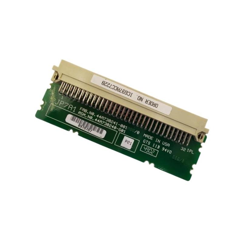
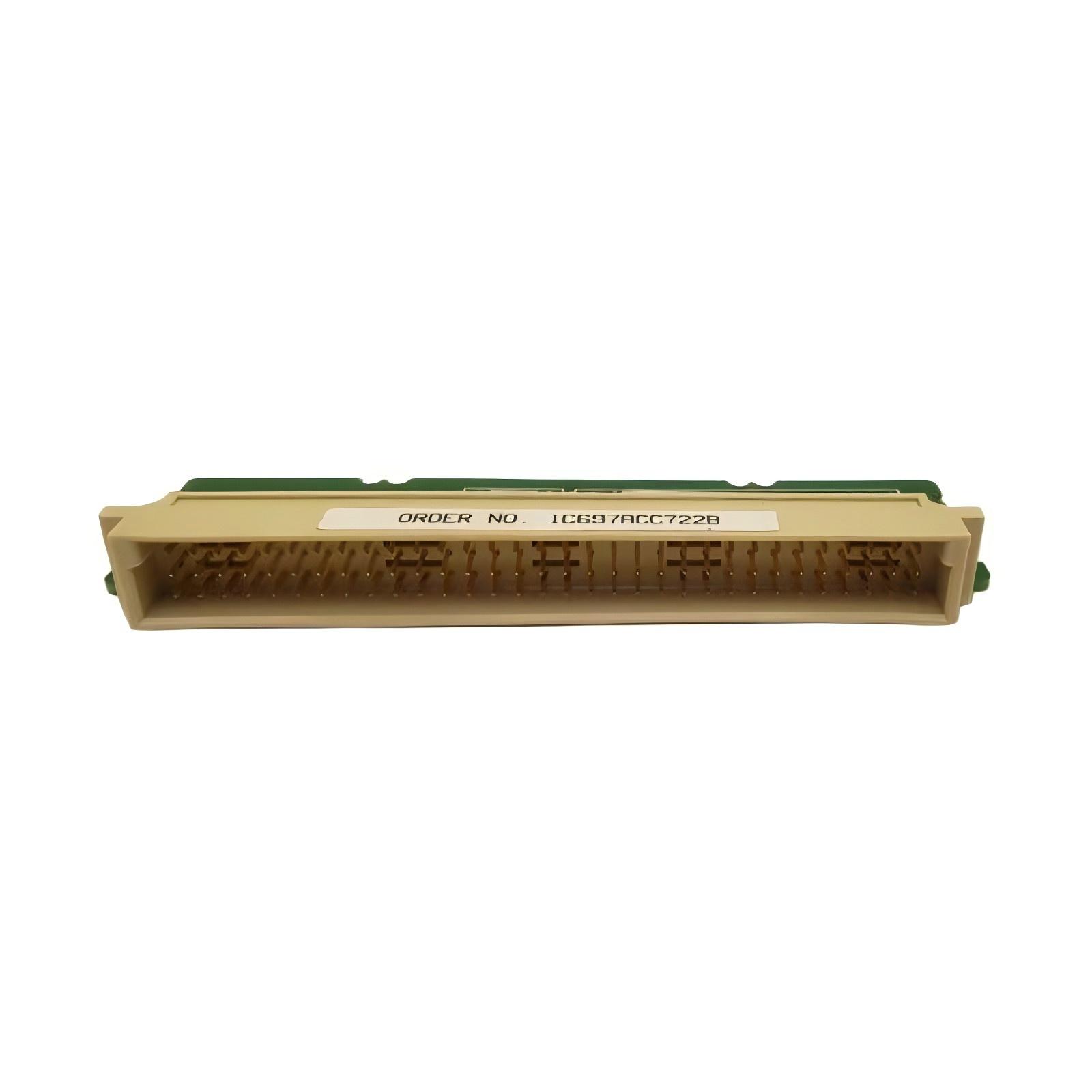
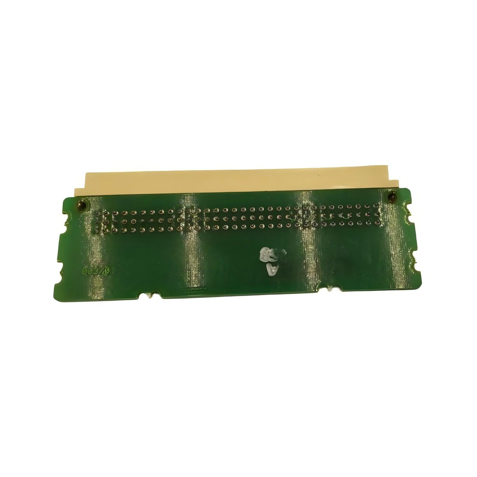
- GE
- IC697ACC722B
- VME Backplane Connector
- USA
- 150 × 25 × 15 mm
- 0.08 kg
- Xiamen, China
- New & In Stock
- T/T, PayPal, Western Union
- 1 Year
- 1-3 Working Days
- DHL, UPS, TNT, FedEx and EMS.
- 24-Hour Service
- COO
- 43
Our advantage

Global Logistics
We have a 10-year logistics and express cooperation agreement, so our products can be shipped to any place in the world.

Brand new and original
Our products are imported in bulk from the place of origin. Because of the cooperative relationship, our products are all original and 100% new.

24-hour service
We provide 7*24 hours service to our customers. We will be there whenever you need us.

Price advantage
All our products are priced very favorably because we have our own warehouse and supply.
| Company Information | |||
| [email protected] | |||
| Mobile | +8615980777398 | ||
| +8615980777398 | |||
| 15980777398 |
Product Overview
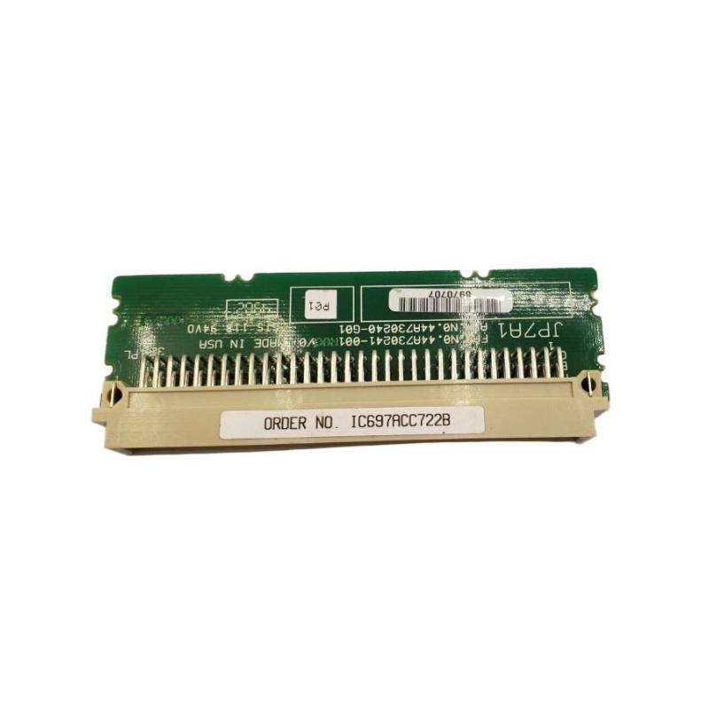
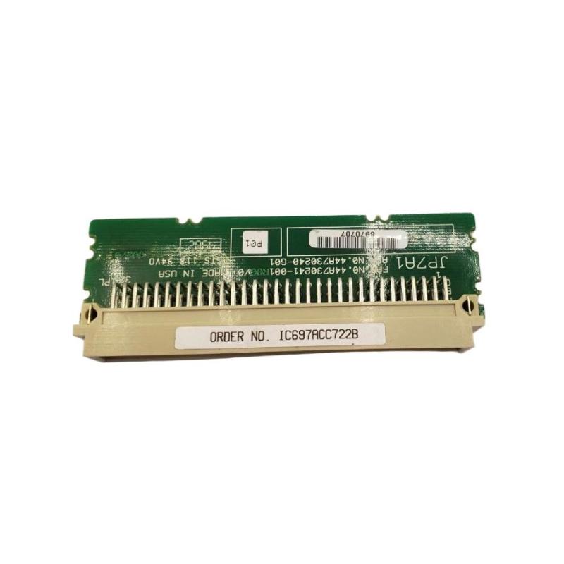
The GE IC697ACC722B VME Backplane Connector is an interconnection accessory associated with GE Series 90-70 industrial control systems. The IC697ACC722 family is identified as a VME backplane connector / interrupt-jumper accessory, rather than a conventional field-wiring connector. Its role is to maintain the required interrupt-path continuity through an unused rack position in applicable VME-based configurations.
This distinction is important during installation. When a rack contains an empty slot but additional modules are installed farther to the right, the interrupt signal may need to continue through that empty position. The corresponding jumper provides that continuity. It is therefore a small component with an important system-level function.
The supplied physical specifications for the GE IC697ACC722B are 150 × 25 × 15 mm, with a listed weight of 0.08 kg.
Product Identification
| Parameter | Specification |
|---|---|
| Manufacturer | GE |
| Model | IC697ACC722B |
| Product Type | VME Backplane Connector |
| Functional Type | Interrupt Jumper / Backplane Accessory |
| Product Family | GE Series 90-70 |
| Primary Function | Interrupt Signal Continuation |
| Dimensions | 150 × 25 × 15 mm |
| Weight | 0.08 kg |
| Installation | Compatible IC697 PLC Rack |
| Application | Industrial Automation / PLC Systems |
| Maintenance | Connector and Configuration Inspection |
Technical Specifications
| Technical Item | Specification |
|---|---|
| Brand | GE |
| Model Number | IC697ACC722B |
| Product Type | VME Backplane Connector |
| Application | Series 90-70 PLC |
| Function | Blank-Slot Interrupt Signal Continuity |
| Interface | VME Backplane |
| Dimensions | 150 × 25 × 15 mm |
| Weight | 0.08 kg |
| Installation Type | Rack Backplane Connection |
| Electrical Role | Interrupt Signal Path |
| Maintenance Requirement | Periodic Mechanical and Configuration Check |
The standard IC697ACC722 is documented as a VME backplane connector with an interrupt-jumper function, and the IC697ACC722B is identified in equipment listings as a VME backplane connector variant.
Understanding the Interrupt Jumper Function
The IC697ACC722B should not be treated simply as a generic VME connector.
In a Series 90-70 rack, an empty module position can interrupt the backplane interrupt path. When modules that may generate interrupts are installed farther to the right, a suitable jumper can be required to continue that interrupt signal through the empty position.
A simplified arrangement is:
CPU / Controller
↓
Rack Backplane
↓
Occupied Slot
↓
IC697ACC722B
↓
Empty Slot / Reserved Position
↓
Additional VME or Control Module
The exact rack position and configuration must follow the applicable system architecture.
Main Functions
Interrupt Signal Continuity
The primary purpose of the jumper is to maintain continuity of the interrupt path through an otherwise empty rack position.
Backplane Interconnection
The component mates with the corresponding backplane connection and provides the required electrical path.
Empty-Slot Support
It allows a rack to contain an unused or reserved position without necessarily interrupting the required interrupt signal path.
Future Expansion
The accessory can be used when a slot is intentionally reserved for future system expansion while modules remain installed farther along the rack.
Typical System Application
The IC697ACC722B is associated with GE Series 90-70 PLC rack architectures.
A representative arrangement can be:
| Rack Position | Example Function |
|---|---|
| Slot 1 | CPU |
| Slot 2 | Control / I/O Module |
| Slot 3 | Empty / Reserved |
| Slot 4 | Additional Module |
| Slot 5 | Additional Module |
If the empty position affects the interrupt path, the appropriate jumper arrangement must be provided.
The exact requirement depends on the rack type, slot position, and installed modules.
Important Installation Position Considerations
The interrupt jumper is not intended to be installed indiscriminately in every rack position.
For the documented IC697ACC722 configuration, the jumper may be used in certain intermediate slots of compatible racks when required to preserve the interrupt path. It should not be installed in the CPU slot, and the last rack slot does not require the jumper in the described configurations.
Therefore, before installation, verify:
- Rack type
- Slot number
- CPU position
- Empty slot location
- Modules installed to the right
- Interrupt requirements
- Controller configuration
Installation Guide
1. Identify the Rack Configuration
Before installing the IC697ACC722B, document the rack layout.
Record:
- Rack type
- Number of slots
- CPU position
- Empty slot
- Installed modules
- Module positions
- Reserved expansion positions
This is especially important because the jumper’s function depends on its location within the rack.
2. Verify the Replacement Part
Confirm:
GE IC697ACC722B
Check:
- Part number
- Connector configuration
- Physical condition
- Mating interface
- Mechanical dimensions
The supplied dimensions are:
150 × 25 × 15 mm
The supplied weight is:
0.08 kg
3. Back Up the PLC Configuration
Before changing rack hardware:
- Save the PLC application program.
- Record the hardware configuration.
- Document existing slot assignments.
- Record any active diagnostic conditions.
- Keep a verified backup available.
This is particularly important because changes involving rack configuration may require configuration verification after installation.
4. Shut Down the System
Before servicing the backplane:
- Stop the controlled process.
- Shut down the PLC according to plant procedures.
- Isolate the applicable electrical power.
- Follow lockout/tagout requirements.
- Verify that the rack is safe to service.
Do not remove or install backplane-connected hardware while energized unless the specific system procedure explicitly permits it.
5. Inspect the Backplane
Inspect the mating backplane connector for:
- Bent contacts
- Contamination
- Corrosion
- Foreign material
- Mechanical damage
A defective backplane interface can produce the same symptoms as a defective jumper.
6. Inspect the IC697ACC722B
Check the replacement component for:
- Damaged connector
- Bent contacts
- Cracked housing
- Contamination
- Mechanical deformation
Do not install a damaged component.
7. Install the Jumper
Align the connector carefully with the designated backplane position.
Insert the IC697ACC722B evenly and ensure it is fully seated.
Do not force the connector.
If resistance is abnormal, remove it and inspect both mating surfaces.
8. Verify Mechanical Seating
After installation, confirm:
- Connector is fully engaged
- Jumper is correctly oriented
- No visible mechanical damage exists
- Adjacent modules are properly seated
- No wiring is interfering with the component
9. Update the System Configuration
The interrupt jumper may need to be included in the controller’s hardware configuration when applicable. The documented IC697ACC722 configuration requires the jumper to be added to the system configuration using the appropriate programming/configuration function.
This step should not be skipped simply because the component is physically small.
10. Restore Power
After completing installation:
- Inspect the rack.
- Confirm all modules are seated.
- Restore power.
- Allow the controller to initialize.
- Check diagnostics.
- Verify module status.
11. Test the System
Confirm:
- CPU starts normally
- Rack initializes correctly
- Modules are recognized
- No unexpected interrupt faults appear
- Communication operates normally
- Application logic runs correctly
Commissioning Checklist
| Item | Verification |
|---|---|
| IC697ACC722B Identified | Confirmed |
| Rack Type Verified | Confirmed |
| Slot Position Checked | Confirmed |
| CPU Position Verified | Confirmed |
| Empty Slot Confirmed | Confirmed |
| Modules to Right Identified | Confirmed |
| PLC Backup Completed | Confirmed |
| Power Isolated | Confirmed |
| Backplane Inspected | Confirmed |
| Jumper Installed | Confirmed |
| Configuration Updated | Confirmed |
| PLC Restarted | Confirmed |
| Diagnostics Checked | Confirmed |
Troubleshooting Guide
Rack Does Not Initialize Correctly
Possible causes include:
- Jumper not installed where required
- Incorrect jumper position
- Poor backplane connection
- Incorrect hardware configuration
- Damaged connector
Start by comparing the physical rack layout with the programmed configuration.
Interrupt-Related Fault
If the controller reports an interrupt-related problem, inspect:
- Empty rack positions
- IC697ACC722B installation
- Module positions
- Backplane connections
- Hardware configuration
An incorrectly positioned jumper can prevent the expected interrupt path from being maintained.
Module on the Right Side of an Empty Slot Is Not Operating Correctly
Possible causes include:
- Interrupt path not continued
- Jumper improperly seated
- Incorrect slot configuration
- Backplane fault
- Module configuration issue
Inspect the intermediate empty slot and jumper before replacing the affected module.
Intermittent Module Faults
Possible causes:
- Poor connector contact
- Vibration
- Contamination
- Damaged backplane interface
- Loose module seating
Inspect the complete mechanical connection.
PLC Reports Configuration Mismatch
Possible causes include:
- Physical jumper installed but not reflected in configuration
- Incorrect rack slot assignment
- Changed module arrangement
- Incorrect hardware configuration
Compare the actual rack with the controller’s configured hardware structure.
Jumper Does Not Fit
Possible causes:
- Incorrect part
- Wrong orientation
- Damaged connector
- Damaged backplane interface
- Foreign material
Never force the connector into the rack.
Multiple Modules Experience Interrupt Problems
If several modules show related interrupt symptoms, inspect the common backplane interrupt path.
Potential causes include:
- Missing jumper
- Incorrect jumper location
- Backplane fault
- Rack configuration problem
A common backplane issue should be investigated before replacing multiple modules.
Preventive Maintenance
Routine Inspection
During scheduled PLC maintenance, inspect:
- Jumper seating
- Connector condition
- Backplane condition
- Module seating
- Rack configuration
Environmental Inspection
Check for:
- Dust
- Moisture
- Condensation
- Corrosion
- Excessive vibration
These conditions can reduce connector reliability.
Configuration Review
When modules are added, removed, or relocated, review the hardware configuration to ensure that interrupt-related accessories remain correctly implemented.
Maintenance Checklist
| Inspection Item | Status |
|---|---|
| Jumper Housing Inspected | ✓ |
| Connector Contacts Checked | ✓ |
| Backplane Interface Inspected | ✓ |
| Jumper Seating Verified | ✓ |
| Rack Slot Position Verified | ✓ |
| Adjacent Modules Checked | ✓ |
| Hardware Configuration Reviewed | ✓ |
| PLC Diagnostics Checked | ✓ |
| Interrupt Operation Verified | ✓ |
Replacement Considerations
When replacing a GE IC697ACC722B, check the following:
| Check Item | Purpose |
|---|---|
| Exact Model | Confirms correct component |
| Rack Type | Ensures system compatibility |
| Slot Position | Determines whether jumper is required |
| Backplane Interface | Ensures mechanical fit |
| Interrupt Architecture | Confirms electrical function |
| Module Arrangement | Determines signal-continuity requirements |
| Configuration | Keeps hardware and software synchronized |
| Environmental Condition | Supports long-term reliability |
Related System Components
| Component | Function |
|---|---|
| GE Series 90-70 CPU | Main Controller |
| IC697 Rack | Houses Control Modules |
| VME Backplane | Internal Module Interconnection |
| IC697ACC722B | Interrupt Path Jumper |
| I/O Modules | Field Signal Processing |
| VME Modules | Additional Control / Interface Functions |
| Power Supply | System Power |
| Programming Software | Hardware Configuration |
The Series 90-70 architecture uses a VME-based system structure, and compatible VME modules can be integrated into the rack architecture under the applicable configuration rules.
Key Advantages
Maintains Interrupt Continuity
The primary value of the IC697ACC722B is maintaining the required interrupt path through an applicable empty rack position.
Supports Flexible Rack Layouts
It allows certain intermediate rack positions to remain empty or reserved while maintaining the required system architecture.
Compact Design
The supplied dimensions are 150 × 25 × 15 mm, making it a relatively small component within the PLC rack.
Lightweight
The listed weight is only 0.08 kg, allowing easy handling during maintenance.
Supports System Expansion
A properly configured reserved slot can simplify future rack expansion while maintaining the required interrupt architecture.
Frequently Asked Questions
What is the GE IC697ACC722B?
The GE IC697ACC722B is a VME backplane connector / interrupt-jumper accessory associated with GE Series 90-70 PLC rack systems.
What are its dimensions?
The supplied dimensions are:
150 × 25 × 15 mm
What is its weight?
The supplied weight is:
0.08 kg
What is the primary purpose of the IC697ACC722B?
Its primary function is to maintain continuity of the rack’s interrupt signal path through an applicable empty slot.
Is it simply a standard VME connector?
No. Its application is more specific. The IC697ACC722 family is documented as a VME Backplane Connector, Interrupt Jumper, and its purpose is related to interrupt-path continuity.
Where is the jumper installed?
The appropriate position depends on the rack configuration. It is used in applicable intermediate empty slots when modules installed farther to the right require interrupt continuity. It should not simply be installed in every empty slot.
Can it be installed in the CPU slot?
No. The documented installation guidance specifically indicates that the jumper should not be installed in slot 1.
Does the jumper need to be configured in software?
For the documented Series 90-70 application, the jumper should be added to the system configuration using the applicable programming/configuration function.
What causes interrupt-related faults after installation?
Common possibilities include:
- Incorrect slot position
- Poor connector seating
- Missing configuration
- Incorrect rack layout
- Backplane problems
Can the IC697ACC722B be replaced while energized?
Backplane maintenance should normally be performed with the applicable power isolated unless the host system explicitly provides an approved energized replacement procedure.
Installation Checklist
| Item | Status |
|---|---|
| Correct IC697ACC722B Identified | ✓ |
| Series 90-70 Rack Verified | ✓ |
| Rack Slot Arrangement Documented | ✓ |
| Empty Slot Identified | ✓ |
| Interrupt Requirement Confirmed | ✓ |
| PLC Program Backed Up | ✓ |
| Power Isolated | ✓ |
| Backplane Inspected | ✓ |
| Jumper Installed Correctly | ✓ |
| Physical Connection Verified | ✓ |
| Hardware Configuration Updated | ✓ |
| Controller Restarted | ✓ |
| Diagnostics Checked | ✓ |
| System Operation Verified | ✓ |
Conclusion
The GE IC697ACC722B VME Backplane Connector is a specialized accessory for compatible GE Series 90-70 control-system rack configurations. Its importance comes not from its physical size, but from its role in maintaining the required interrupt signal path through an applicable unused rack position.
The supplied dimensions are 150 × 25 × 15 mm, with a listed weight of 0.08 kg. When installing or replacing the component, technicians should verify the rack type, slot position, adjacent modules, backplane condition, and controller hardware configuration.
A missing or incorrectly positioned interrupt jumper can produce system-level symptoms that may initially appear to be caused by an I/O or VME module. For this reason, troubleshooting should begin by comparing the physical rack arrangement with the intended hardware configuration and checking the jumper’s seating and location.
When correctly installed and configured, the GE IC697ACC722B helps preserve reliable interrupt-path continuity and supports flexible rack layouts in compatible GE industrial automation systems.