

ProductPRODUCT
Featured products


Contact Us

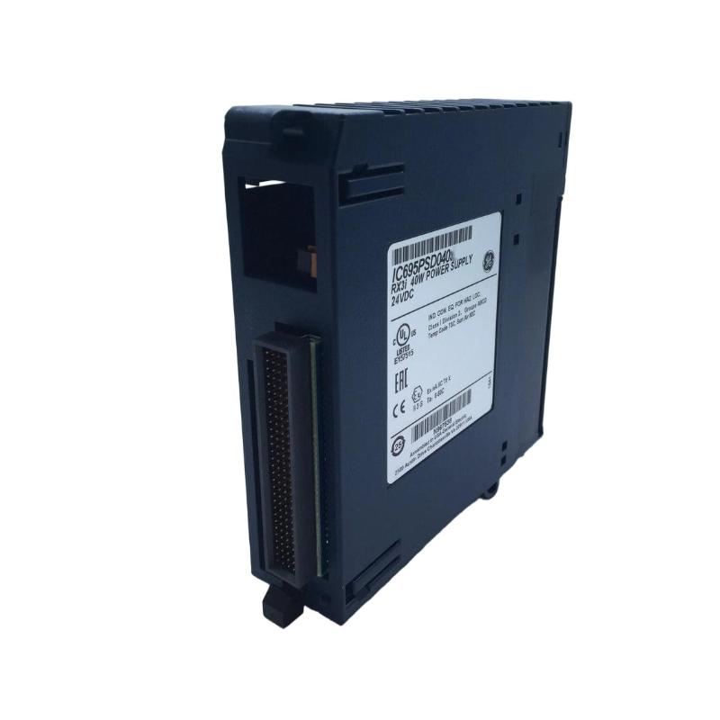
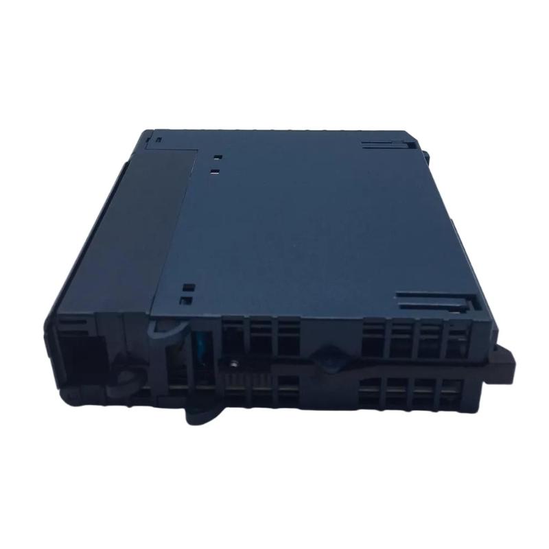
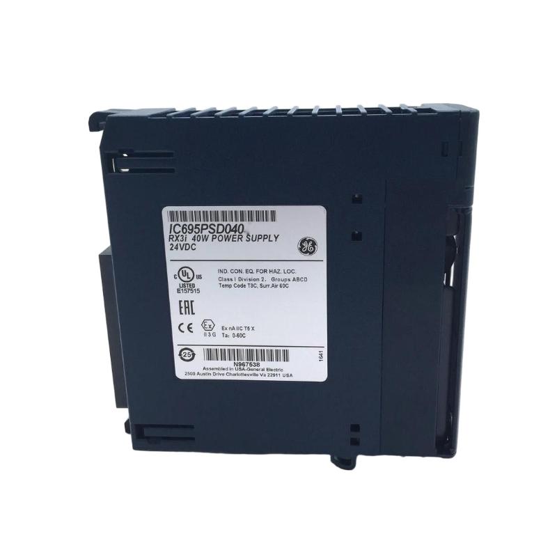
- GE
- IC695PDSD040
- RX3i Universal Backplane
- USA
- 185 × 120 × 50 mm
- 1 kg
- Xiamen, China
- New & In Stock
- T/T, PayPal, Western Union
- 1 Year
- 1-3 Working Days
- DHL, UPS, TNT, FedEx and EMS.
- 24-Hour Service
- COO
- 71
Our advantage

Global Logistics
We have a 10-year logistics and express cooperation agreement, so our products can be shipped to any place in the world.

Brand new and original
Our products are imported in bulk from the place of origin. Because of the cooperative relationship, our products are all original and 100% new.

24-hour service
We provide 7*24 hours service to our customers. We will be there whenever you need us.

Price advantage
All our products are priced very favorably because we have our own warehouse and supply.
| Company Information | |||
| [email protected] | |||
| Mobile | +8615980777398 | ||
| +8615980777398 | |||
| 15980777398 |
Product Overview
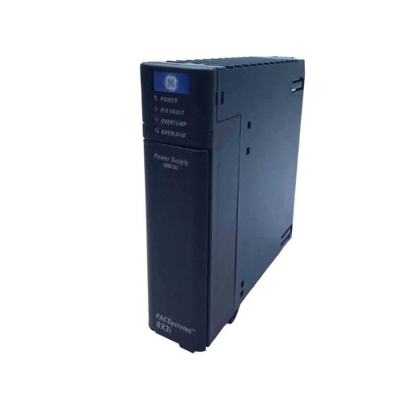
The GE IC695PDSD040 is an RX3i Universal Backplane used as a central hardware interconnection platform within a PACSystems RX3i control system. The backplane provides the physical mounting structure and electrical interconnection required for compatible RX3i modules to operate together as an integrated automation system.
In a modular PLC architecture, the backplane is more than a mechanical mounting component. It provides the infrastructure through which installed modules can exchange information and receive the required system connections. A problem with the backplane, its connectors, or its installation can therefore affect multiple modules simultaneously.
The specified dimensions of the GE IC695PDSD040 are 185 × 120 × 50 mm, with a weight of approximately 1 kg.
Because the backplane forms the foundation of a modular control system, careful installation, module seating, power verification, and inspection of the interconnection points are important for maintaining system reliability.
This guide covers the IC695PDSD040 product characteristics, system role, installation procedure, commissioning, troubleshooting, preventive maintenance, and replacement considerations.
Product Identification
| Parameter | Specification |
|---|---|
| Manufacturer | GE |
| Product Family | PACSystems RX3i |
| Model | IC695PDSD040 |
| Product Type | RX3i Universal Backplane |
| Primary Function | Module Mounting and System Interconnection |
| Dimensions | 185 × 120 × 50 mm |
| Weight | Approximately 1 kg |
| Installation | RX3i Control System |
| Application | Modular PLC / Industrial Automation |
| System Role | Backplane and Module Interconnection |
Technical Specifications
| Technical Item | Specification |
|---|---|
| Product Series | PACSystems RX3i |
| Part Number | IC695PDSD040 |
| Component Type | Universal Backplane |
| Height | 185 mm |
| Width | 120 mm |
| Depth | 50 mm |
| Weight | Approximately 1 kg |
| Primary Function | Module Interconnection |
| Installation Environment | Industrial Control Cabinet |
| Application | RX3i Modular Automation |
| System Architecture | PACSystems RX3i |
What Is the GE IC695PDSD040?
The IC695PDSD040 serves as the structural and electrical foundation for compatible RX3i modules.
In a modular PLC system, individual modules perform different functions:
- CPU processing
- Digital inputs
- Digital outputs
- Analog inputs
- Analog outputs
- Communication
- High-speed counting
- Specialized control
The backplane provides the platform on which these modules are installed and interconnected.
A simplified architecture is:
Power Supply
↓
RX3i Backplane
↓
CPU / Controller
↓
I/O Modules
↓
Communication Modules
↓
Field Devices
Without a properly installed and functioning backplane, the individual modules cannot operate as an integrated system.
Role of the Backplane in an RX3i System
The backplane has several important functions.
Mechanical Mounting
It provides the physical structure for installing the compatible control-system modules.
Electrical Interconnection
Installed modules depend on the backplane interface for system-level electrical connections.
System Organization
The backplane establishes the physical arrangement of modules inside the control cabinet.
Module Communication
The system architecture uses the backplane as an internal pathway for module-level data exchange.
Power Distribution
The backplane participates in the system’s internal module interconnection and power architecture.
Why Backplane Reliability Matters
A backplane problem can affect more than one module.
For example, if a single I/O module has a fault, the problem may be isolated to one channel or one module.
However, if the backplane has a connection or hardware problem, multiple modules may simultaneously exhibit:
- Communication errors
- Startup failures
- Missing module conditions
- Intermittent operation
- Diagnostic faults
- Unexpected resets
This makes backplane troubleshooting particularly important in modular PLC systems.
Typical Industrial Applications
The GE IC695PDSD040 can be used as part of RX3i automation systems in applications such as:
- Factory automation
- Machine control
- Packaging equipment
- Conveyor systems
- Material handling
- Process automation
- Water treatment
- Energy systems
- Manufacturing lines
- Chemical processing
- Food and beverage production
- Pharmaceutical automation
The specific application depends on the complete RX3i hardware configuration.
System Integration
A typical RX3i system can contain:
| Component | Function |
|---|---|
| IC695PDSD040 | Universal backplane |
| RX3i CPU | Central processing |
| RX3i Power Supply | System power |
| Digital Input Modules | Discrete signal acquisition |
| Digital Output Modules | Discrete control |
| Analog Input Modules | Analog measurement |
| Analog Output Modules | Analog control |
| High-Speed Counter | Fast pulse processing |
| Communication Modules | Network communication |
| Field Devices | Sensors and switches |
| Actuators | Motors, valves, and other equipment |
The backplane provides the physical and electrical foundation for the modular architecture.
Installation Guide
1. Verify the Product
Confirm the part number:
GE IC695PDSD040
Verify that the selected backplane matches the system engineering documentation.
2. Inspect the Backplane
Before installation, inspect the unit for:
- Physical damage
- Cracked housing
- Damaged mounting points
- Damaged module interfaces
- Bent or contaminated connectors
- Signs of overheating
Do not install damaged equipment.
3. Confirm System Layout
Before mounting the backplane, determine:
- Cabinet position
- Module arrangement
- Power supply location
- CPU position
- I/O module positions
- Communication module positions
- Cable routing
A well-planned arrangement makes future maintenance easier.
4. Prepare the Control Cabinet
The specified dimensions are:
185 × 120 × 50 mm
Provide adequate clearance for:
- Module installation
- Cable routing
- Ventilation
- Inspection
- Maintenance
- Module removal
Avoid positioning the backplane close to strong heat sources.
5. Shut Down the System
For an existing installation:
- Stop the controlled machine.
- Follow the approved shutdown sequence.
- Remove system power.
- Verify the system is safe.
- Apply lockout/tagout procedures where required.
6. Mount the Backplane
Secure the IC695PDSD040 in the designated cabinet location.
Verify:
- Correct orientation
- Secure mechanical mounting
- Proper alignment
- Adequate clearance
- No excessive mechanical stress
7. Install the Power Supply
Install the compatible power supply in the designated position according to the system design.
Verify that the power connection is secure.
8. Install the CPU
Install the RX3i CPU in the designated position.
Check:
- Correct alignment
- Proper seating
- Secure retention
- Connector engagement
9. Install I/O and Communication Modules
Install the required modules according to the approved hardware configuration.
Examples may include:
- Digital input modules
- Digital output modules
- Analog input modules
- Analog output modules
- High-speed counter modules
- Communication modules
Each module should be fully seated.
10. Inspect Module Connections
After installation, inspect every module interface.
Check for:
- Incomplete seating
- Contamination
- Mechanical damage
- Loose connections
- Incorrect module positioning
Commissioning Procedure
Step 1 — Mechanical Inspection
Verify that the backplane and all modules are securely mounted.
Step 2 — Power Inspection
Check system power connections.
Step 3 — Module Inspection
Confirm that all installed modules correspond to the intended hardware configuration.
Step 4 — Controller Startup
Power up the RX3i system.
Step 5 — Module Recognition
Verify that the controller recognizes the installed modules.
Step 6 — Diagnostic Review
Check controller and module diagnostic information.
Step 7 — I/O Test
Test representative input and output channels.
Step 8 — Communication Test
If communication modules are installed, verify network operation.
Step 9 — Machine Test
Operate the machine under controlled conditions.
Step 10 — Final Verification
Confirm stable operation without recurring module or backplane-related diagnostics.
Troubleshooting Guide
Fault 1 — Multiple Modules Fail Simultaneously
Possible causes:
- Backplane problem
- Power supply problem
- Poor module seating
- System-level connection issue
- Controller problem
If several modules fail at the same time, investigate the common infrastructure before replacing individual I/O modules.
Fault 2 — One Module Is Not Recognized
Possible causes:
- Module not fully seated
- Connector contamination
- Incorrect configuration
- Module failure
- Backplane interface problem
Recommended Checks
- Stop the system safely.
- Remove power.
- Inspect the module connection.
- Reseat the module.
- Restore power.
- Review diagnostics.
Fault 3 — Modules Work Intermittently
Possible causes:
- Loose module connection
- Mechanical vibration
- Backplane connector problem
- Cabinet temperature
- Contamination
- Power instability
Inspect the physical installation carefully.
Fault 4 — Controller Reports Backplane-Related Diagnostics
Possible causes:
- Poor module connection
- Backplane hardware problem
- Power issue
- Incorrect system configuration
- Damaged interface
Record the diagnostic information before making changes.
Fault 5 — System Resets Unexpectedly
Possible causes:
- Power interruption
- Backplane connection problem
- Controller issue
- Electrical interference
- Hardware fault
Check whether the reset affects the entire rack or only one module.
Fault 6 — Module Communication Is Lost
Possible causes:
- Poor module seating
- Backplane interface issue
- Module hardware problem
- Controller configuration problem
- Power instability
Compare the affected module with other modules operating normally.
Fault 7 — New Module Does Not Operate After Installation
Possible causes:
- Incorrect hardware configuration
- Incorrect module position
- Incomplete seating
- Backplane connection problem
- Module fault
Verify both the physical and software configuration.
Fault 8 — Several I/O Modules Show Diagnostic Errors
When multiple I/O modules report faults simultaneously, investigate:
- Backplane
- Power supply
- Controller
- Common connections
- Cabinet environment
Replacing several individual I/O modules without checking the common infrastructure can lead to unnecessary maintenance.
Fault 9 — Fault Appears After Cabinet Maintenance
Possible causes:
- Module disturbed during maintenance
- Loose connection
- Damaged connector
- Cable interference
- Power connection disturbed
Inspect recently serviced components first.
Fault 10 — System Works at Startup but Fails Later
Possible causes:
- Thermal condition
- Vibration
- Intermittent connection
- Power instability
- Environmental contamination
Monitor the system while the fault develops.
Backplane Diagnostic Workflow
A systematic troubleshooting sequence is:
Incoming Power
↓
Power Supply
↓
IC695PDSD040 Backplane
↓
CPU
↓
Individual Modules
↓
Controller Diagnostics
↓
Field I/O
↓
Network Communication
↓
Machine Operation
This approach makes it easier to distinguish between a local module fault and a common system infrastructure fault.
Preventive Maintenance
Backplane Inspection
Inspect:
- Housing
- Mounting points
- Module interfaces
- Connectors
- Signs of overheating
Module Inspection
Check:
- Module seating
- Mechanical retention
- Status indicators
- Connector condition
Power Inspection
Monitor:
- Supply stability
- Connections
- Signs of overheating
- Unexpected system resets
Cabinet Inspection
Check:
- Temperature
- Dust
- Moisture
- Vibration
- Ventilation
- Electrical interference
Preventive Maintenance Checklist
| Inspection Item | Recommended Action |
|---|---|
| IC695PDSD040 | Inspect physical condition |
| Mounting | Verify secure attachment |
| Module Interfaces | Inspect for damage or contamination |
| Module Seating | Verify secure installation |
| Power Connections | Check security |
| System Power | Monitor stability |
| Cabinet Temperature | Monitor operating conditions |
| Ventilation | Keep airflow paths clear |
| Vibration | Check for excessive vibration |
| Diagnostics | Review recurring faults |
| Configuration | Maintain current backup |
Backplane Replacement Procedure
Step 1 — Back Up the PLC
Save the current:
- PLC program
- Hardware configuration
- Network configuration
- Module configuration
Step 2 — Document the Existing System
Record:
- Module positions
- Power supply arrangement
- CPU location
- I/O configuration
- Communication connections
Step 3 — Stop the Machine
Place the process in a safe condition.
Step 4 — Remove Power
Follow the approved shutdown and lockout/tagout procedure.
Step 5 — Label Connections
Clearly identify wiring and network connections before removal.
Step 6 — Remove Modules
Carefully remove installed modules according to the approved maintenance procedure.
Step 7 — Remove the Existing Backplane
Disconnect the necessary connections and remove the existing backplane.
Step 8 — Inspect the Cabinet
Check mounting surfaces and surrounding equipment.
Step 9 — Install the Replacement
Install the replacement IC695PDSD040 securely.
Step 10 — Reinstall Modules
Return the CPU, power supply, I/O modules, and communication modules to their documented positions.
Step 11 — Verify Connections
Inspect every module interface.
Step 12 — Restore Power
Power up the system.
Step 13 — Verify Module Recognition
Confirm that the controller recognizes the installed hardware.
Step 14 — Test I/O
Verify representative inputs and outputs.
Step 15 — Test Communications
Verify network-connected equipment where applicable.
Step 16 — Return to Service
Return the machine to normal operation after successful testing.
Key Advantages
- Provides a modular foundation for RX3i control systems
- Supports organized installation of compatible automation modules
- Provides system-level module interconnection
- Simplifies modular PLC architecture
- Supports centralized arrangement of CPU, I/O, and communication hardware
- Suitable for industrial control cabinet installations
- Specified dimensions of 185 × 120 × 50 mm
- Approximately 1 kg weight
- Facilitates structured system maintenance
- Provides a common infrastructure for modular control hardware
Frequently Asked Questions
What is the GE IC695PDSD040?
The GE IC695PDSD040 is an RX3i Universal Backplane used to mount and interconnect compatible RX3i automation modules.
What are the dimensions?
The specified dimensions are:
185 × 120 × 50 mm
What is the weight?
Approximately 1 kg.
What is the purpose of an RX3i backplane?
The backplane provides the physical mounting and system-level electrical interconnection required by the modular control system.
Can a backplane problem affect multiple modules?
Yes. Because multiple modules depend on the common backplane infrastructure, a backplane or system-level connection problem can affect several modules simultaneously.
Why is one module not recognized?
Possible causes include poor module seating, connector contamination, configuration errors, a module fault, or a problem with the corresponding backplane interface.
Why do several modules report faults simultaneously?
Check common infrastructure first, especially system power, backplane connections, controller status, and environmental conditions.
What should be checked after replacing the backplane?
Verify module positions, module seating, power connections, controller configuration, I/O operation, communication, and system diagnostics.
Conclusion
The GE IC695PDSD040 RX3i Universal Backplane provides the physical and electrical foundation required for a modular RX3i automation system. With specified dimensions of 185 × 120 × 50 mm and a weight of approximately 1 kg, it is designed to support the organized installation and interconnection of compatible control-system modules.
The backplane is a critical part of the system infrastructure because the CPU, I/O modules, communication modules, and other installed components depend on reliable mechanical and electrical interconnection. Consequently, a backplane-related problem can produce symptoms across multiple modules rather than appearing as a single isolated I/O fault.
Proper installation requires secure mounting, correct module seating, stable power, adequate cabinet clearance, and careful inspection of the module interfaces. During commissioning, technicians should verify module recognition, controller diagnostics, I/O operation, and communication performance.
When troubleshooting an IC695PDSD040 system, a fault affecting multiple modules should immediately prompt an investigation of common system infrastructure such as the power supply and backplane. A structured diagnostic process can prevent unnecessary replacement of otherwise functional I/O or communication modules.
With appropriate installation, preventive maintenance, configuration backups, environmental control, and systematic troubleshooting, the IC695PDSD040 can provide a dependable foundation for RX3i modular industrial automation systems.