

ProductPRODUCT
Featured products
Contact Us
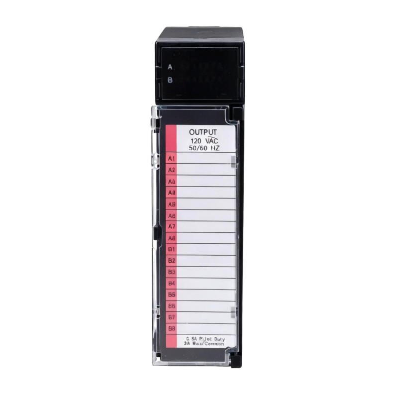
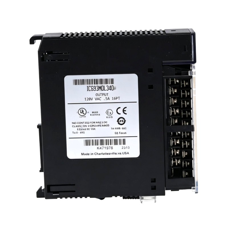
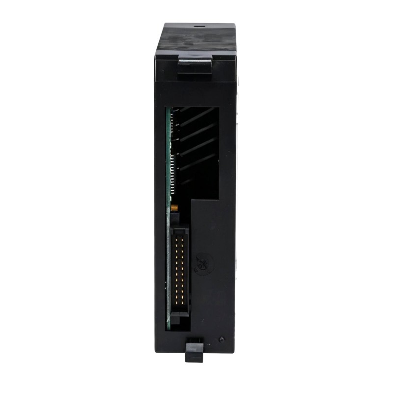
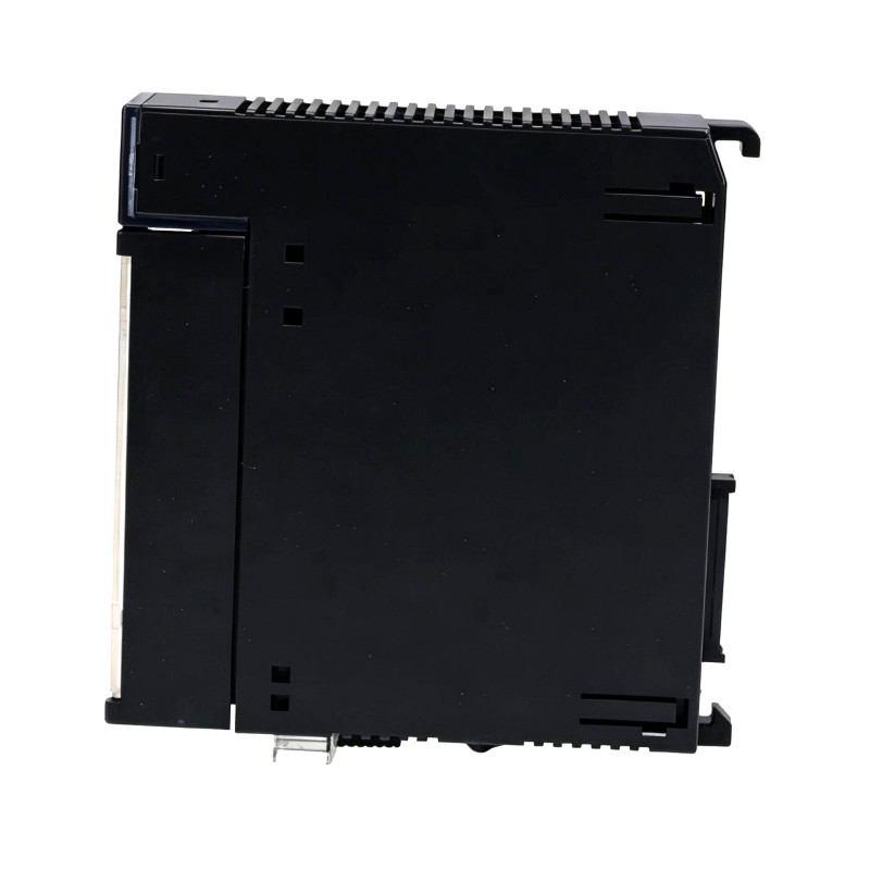
- GE
- IC693MDL340D
- AC Voltage Output Module
- USA
- 142 × 30 × 130 mm
- 0.35 kg
- Xiamen, China
- New & In Stock
- T/T, PayPal, Western Union
- 1 Year
- 1-3 Working Days
- DHL, UPS, TNT, FedEx and EMS.
- 24-Hour Service
- COO
- 5
Our advantage

Global Logistics
We have a 10-year logistics and express cooperation agreement, so our products can be shipped to any place in the world.

Brand new and original
Our products are imported in bulk from the place of origin. Because of the cooperative relationship, our products are all original and 100% new.

24-hour service
We provide 7*24 hours service to our customers. We will be there whenever you need us.

Price advantage
All our products are priced very favorably because we have our own warehouse and supply.
| Company Information | |||
| [email protected] | |||
| Mobile | +8615980777398 | ||
| +8615980777398 | |||
| 15980777398 |
Product Overview
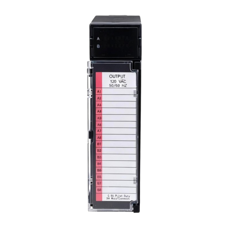
The GE IC693MDL340D is a Series 90-30 AC Voltage Output Module used when a PLC program needs to switch external AC control circuits. It sits between the Series 90-30 controller and the field devices, turning discrete output commands from the PLC into corresponding AC output states.
A typical installation may use the module to operate relay coils, contactors, solenoid circuits, pilot devices, or other compatible AC loads. For machine-control applications, the output state can be linked to conditions such as a start command, sequence step, equipment permissive, or alarm response.
The module is part of the Series 90-30 modular I/O structure, so its practical role depends on the CPU program, rack configuration, field wiring, and connected loads. During troubleshooting, these elements can be checked independently to determine whether an output problem originates in the control logic, I/O module, wiring, or field device.
Technical Specifications
| Parameter | Specification |
|---|---|
| Product Model | IC693MDL340D |
| Product Type | AC Voltage Output Module |
| Series | Series 90-30 |
| Output Function | AC Discrete Output |
| Dimensions | 142 × 30 × 130 mm |
| Weight | 0.35 kg |
Product Features
- AC discrete output interface — Provides switched AC output points for compatible field circuits.
- Series 90-30 compatibility — Forms part of the modular I/O architecture used by GE Series 90-30 PLC systems.
- PLC-controlled switching — Output states are controlled according to the application program running in the PLC.
- Field actuator interfacing — Can be incorporated into control circuits involving relays, contactors, solenoids, and other suitable AC devices.
- Point-level operation monitoring — Individual output behavior can be checked during commissioning and fault diagnosis.
- Modular cabinet installation — Works alongside other Series 90-30 I/O modules to build application-specific control stations.
Working Principle
The IC693MDL340D receives output-state information from the Series 90-30 PLC backplane. When the application logic calls for a particular output point to be energized, the corresponding channel switches its field-side AC circuit.
The resulting electrical state is transmitted through the external wiring to the connected load. In a motor starter application, for example, the module may control a contactor coil rather than the motor itself. The PLC determines the command, the output module switches the control circuit, and the contactor handles the downstream motor circuit.
This separation is useful when diagnosing faults. If the PLC indicates that an output is active but the field device does not respond, the technician can trace the signal from the controller and module through the terminal wiring to the load instead of treating the entire control chain as one component.
Role in a GE Series 90-30 PLC Control Architecture
| Architecture Layer | Role of IC693MDL340D |
|---|---|
| Application Program | Defines when individual output points should change state |
| Series 90-30 CPU | Executes the control logic and updates I/O commands |
| PLC Backplane | Transfers I/O data between the controller and output module |
| IC693MDL340D | Switches the corresponding AC field-side output |
| Terminal / Field Wiring | Carries the output signal to the external control circuit |
| Relay, Contactor, or Load | Responds to the commanded output condition |
The IC693MDL340D is therefore positioned at the boundary between the PLC’s internal logic and its external AC control circuits. Its operation depends on both the Series 90-30 I/O configuration and the electrical design of the connected field circuit.
Industrial Applications
| Application | Typical Use |
|---|---|
| Motor Starter Panels | Switching compatible contactor control circuits |
| Conveyor Machinery | Activating AC control devices according to machine sequences |
| Packaging Equipment | Operating relays, solenoids, and auxiliary actuators |
| Material Handling Systems | Providing discrete AC commands to field equipment |
| Industrial Machine Control | Coordinating external devices with PLC program states |
| Process Skids | Switching auxiliary AC control circuits associated with pumps and valves |
| Equipment Retrofit | Updating existing Series 90-30 output positions without changing the overall PLC platform |
Installation and Maintenance
- Confirm the output application — Verify that the IC693MDL340D is the correct output type for the intended AC control circuit.
- Check the PLC configuration — Confirm the module position and output-point assignments in the Series 90-30 hardware configuration.
- Isolate external power — Disconnect the relevant field-side power and follow the site’s electrical safety procedure before servicing the module.
- Inspect the module connection — Check the rack interface and module seating for signs of damage or contamination.
- Verify output wiring — Compare field conductors with the current electrical drawings and I/O schedule.
- Check connected loads — Confirm that relays, contactors, solenoids, or other loads are correctly connected to their assigned output points.
- Inspect terminal connections — Look for loose wires, damaged conductors, incorrect terminations, or signs of overheating.
- Check output status — Compare the commanded PLC state with the observed module output condition.
- Perform point-to-point testing — Activate individual output points under controlled commissioning conditions and verify the corresponding field response.
- Check intermediate devices — If a PLC output changes but the final equipment does not respond, inspect the associated relay or contactor circuit.
- Investigate recurring failures — Check load characteristics, wiring, switching frequency, and external circuit conditions before repeatedly replacing the I/O module.
- Record maintenance changes — Update I/O schedules and electrical documentation after module replacement or field-wiring modifications.
Compatible System Components
| Component | Relationship |
|---|---|
| GE Series 90-30 CPU | Executes the application logic that commands the output channels |
| Series 90-30 I/O Rack | Provides the module mounting and backplane interface |
| Series 90-30 Power Supply | Supplies power for the PLC rack and installed modules |
| Series 90-30 Terminal Assembly | Provides the field wiring interface for output circuits |
| Interposing Relays / Contactors | Commonly used between PLC outputs and higher-power equipment |
| AC Field Devices | Receive the switched output commands from the module |
Recommended Related Models
| Model | Product Type | Application Relationship |
|---|---|---|
| GE IC693MDL340D | Series 90-30 AC Voltage Output Module | AC discrete output interface for Series 90-30 PLC systems |
| GE IC693MDL330 | Series 90-30 AC Output Module | Related AC digital output option |
| GE IC693MDL240 | Series 90-30 Relay Output Module | Alternative output architecture using relay switching |
| GE IC693MDL250 | Series 90-30 Relay Output Module | Related relay-output option for discrete control circuits |
| GE IC693CPU | Series 90-30 CPU Module | Provides the PLC processing and logic associated with the I/O system |
Key Advantages
- Provides a dedicated AC output interface within the Series 90-30 I/O system.
- Allows PLC logic to operate compatible external AC control circuits.
- Works naturally with relay and contactor-based machine-control arrangements.
- Supports individual output-point testing during commissioning.
- Makes it possible to isolate PLC, I/O, wiring, and load faults during troubleshooting.
- Fits the modular I/O structure of existing Series 90-30 control cabinets.
Technical FAQs
What is the difference between the IC693MDL340D and a relay output module?
The IC693MDL340D is an AC voltage output module, while a relay output module uses relay contacts to switch the external circuit. The appropriate choice depends on the electrical characteristics and switching requirements of the field load.
Can the IC693MDL340D be used to operate a motor directly?
It should not be treated as a motor-power switching device. In a conventional motor-control arrangement, the PLC output controls an appropriately selected contactor or relay circuit, while the contactor handles the motor’s power circuit.
Why might the PLC show an active output while the field device remains off?
Possible causes include incorrect field wiring, a problem with the terminal connection, an open intermediate relay or contactor circuit, an unsuitable load, or a fault in the output channel. Checking the signal path from the module to the load helps identify the actual point of failure.
What should be considered when replacing an IC693MDL340D in an existing Series 90-30 rack?
The replacement should match the required output function and the existing PLC hardware configuration. Before returning the system to service, verify the module position, output assignments, field wiring, connected load, and point-to-point operation.