

ProductPRODUCT
Featured products
Contact Us
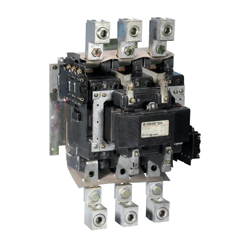
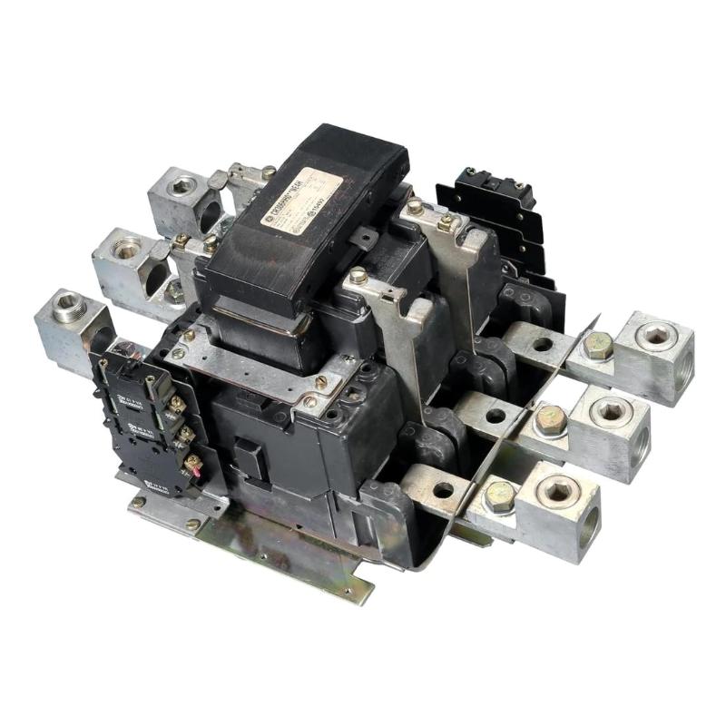
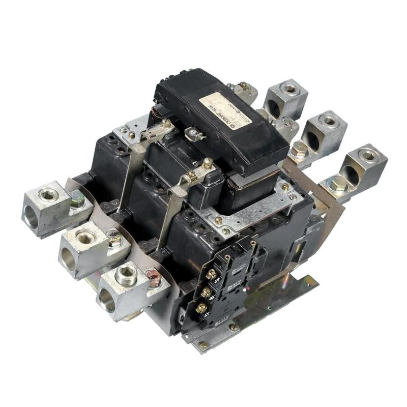
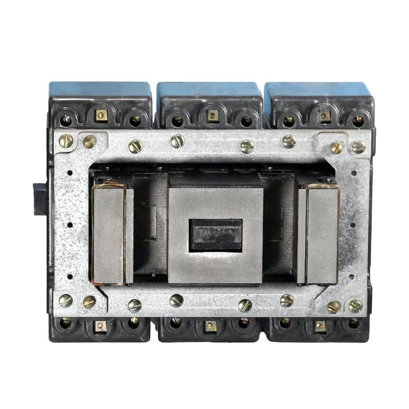
- GE
- CR305HH004BD1H
- CR305 Contactor
- USA
- 580 × 120 × 250 mm
- 14.5 kg
- Xiamen, China
- New & In Stock
- T/T, PayPal, Western Union
- 1 Year
- 1-3 Working Days
- DHL, UPS, TNT, FedEx and EMS.
- 24-Hour Service
- COO
- 4
Our advantage

Global Logistics
We have a 10-year logistics and express cooperation agreement, so our products can be shipped to any place in the world.

Brand new and original
Our products are imported in bulk from the place of origin. Because of the cooperative relationship, our products are all original and 100% new.

24-hour service
We provide 7*24 hours service to our customers. We will be there whenever you need us.

Price advantage
All our products are priced very favorably because we have our own warehouse and supply.
| Company Information | |||
| [email protected] | |||
| Mobile | +8615980777398 | ||
| +8615980777398 | |||
| 15980777398 |
Product Overview
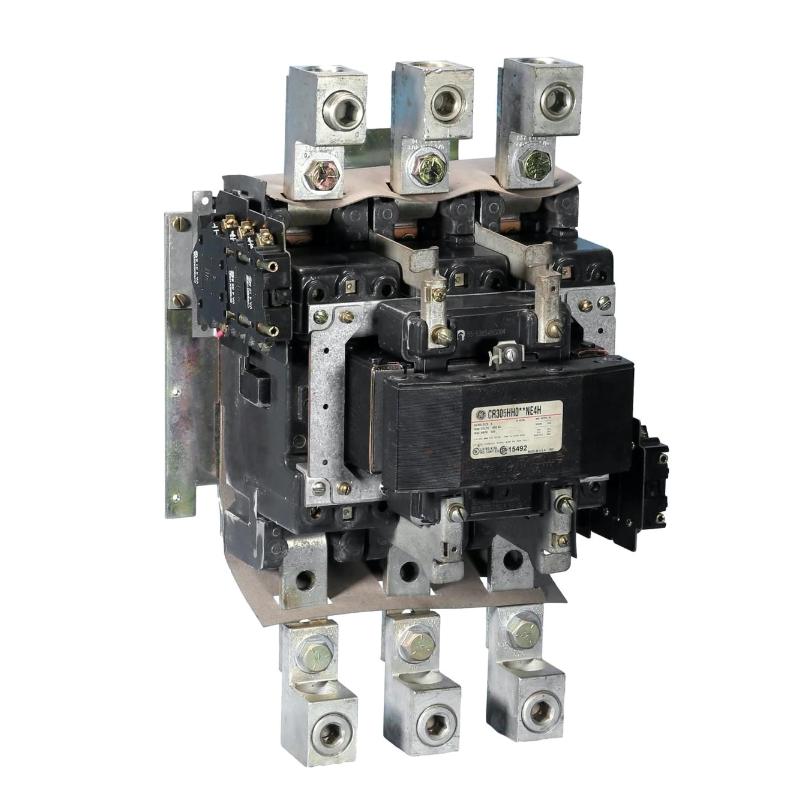
The GE CR305HH004BD1H is a CR305 Contactor used for switching and controlling electrical loads in industrial equipment. It functions as an electromechanical interface between a control circuit and the power circuit, allowing a relatively low-power control command to operate a higher-power load.
In a typical motor-control panel, the contactor may be connected to a starter circuit where its main contacts control the motor power path and its auxiliary contacts participate in interlocks, status indication, or control logic. Similar arrangements can be found in pumps, fans, conveyors, compressors, machine tools, and other electrically driven equipment.
The CR305 platform is commonly encountered in industrial motor-control assemblies where contactor operation needs to coordinate with overload protection, pushbuttons, PLC outputs, safety circuits, and other control components.
Technical Specifications
| Parameter | Specification |
|---|---|
| Product Model | CR305HH004BD1H |
| Product Type | CR305 Contactor |
| Series | CR305 |
| Device Function | Motor and Load Switching |
| Dimensions | 580 × 120 × 250 mm |
| Weight | 14.5 kg |
Product Features
- Electromechanical switching — Uses a control signal to operate the main power contacts.
- CR305 contactor platform — Intended for industrial motor-control and load-switching applications.
- Control and power circuit separation — Keeps the contactor coil control function separate from the switched load circuit.
- Auxiliary contact integration — Supports control schemes that require feedback, interlocking, or status signaling.
- Motor starter applications — Can be integrated with overload protection and other motor-control components.
- Panel-based installation — Suited to industrial control cabinets and equipment starter assemblies.
Working Principle
The CR305HH004BD1H operates by energizing its contactor coil from the associated control circuit. When the coil receives the required command, the contactor mechanism moves the main contacts into their operating state, connecting the controlled power circuit to the load.
When the control command is removed, the coil de-energizes and the contact mechanism returns to its normal state. This allows the control system to start and stop the connected equipment without routing the full load current through a small control device such as a pushbutton or PLC output.
In a motor starter, the contactor normally works together with overload protection. The control circuit can also incorporate auxiliary contacts so that the PLC or other controller can determine whether the contactor has reached the commanded state. This arrangement gives technicians a practical way to separate control-signal problems from power-circuit or mechanical switching problems during troubleshooting.
Role in a GE CR305 Motor Control Architecture
| Architecture Layer | Role of CR305HH004BD1H |
|---|---|
| PLC / Control Device | Generates the start, stop, or interlock command |
| Control Circuit | Carries the contactor coil command through the required permissives |
| CR305 Contactor | Opens or closes the main power path for the controlled load |
| Auxiliary Contacts | Provide status or interlocking signals to the control circuit |
| Overload Protection | Monitors the motor circuit and can interrupt the contactor control path |
| Motor / Electrical Load | Receives power when the contactor is commanded to close |
| Protection / Disconnect Devices | Provide upstream isolation and fault protection |
The contactor is therefore the switching point between the control logic and the power circuit. Its operation depends on the complete starter arrangement, including the coil circuit, protection devices, auxiliary contacts, and connected load.
Industrial Applications
| Application | Typical Use |
|---|---|
| Motor Starters | Switching three-phase or other compatible motor circuits through a starter arrangement |
| Pump Systems | Starting and stopping pumps from local or automated control circuits |
| Fan and Blower Systems | Controlling electrically driven ventilation and process-air equipment |
| Conveyor Systems | Switching drive motors according to machine sequencing |
| Compressor Equipment | Integrating motor switching with compressor control and protection |
| Machine Tools | Controlling motors and auxiliary electrical loads |
| Industrial Control Panels | Providing electromechanical load switching within centralized starter assemblies |
Installation and Maintenance
- Confirm the contactor application — Verify that the CR305 contactor is suitable for the intended load and control arrangement.
- Review the electrical schematic — Identify the coil circuit, main power connections, auxiliary contacts, protection devices, and load connections.
- Isolate all relevant power sources — Follow the site’s electrical safety procedure before installation, inspection, or maintenance.
- Verify terminal identification — Confirm each power and control conductor against the current wiring documentation.
- Inspect the contactor body — Check for mechanical damage, contamination, loose components, or signs of overheating.
- Check coil wiring — Inspect the control-circuit connections and verify that the coil receives the intended command.
- Inspect main contacts — Look for excessive wear, pitting, discoloration, or other signs of abnormal switching conditions.
- Check auxiliary contacts — Verify that auxiliary contact states correspond correctly to the contactor’s mechanical position.
- Inspect mechanical movement — Confirm that the contact mechanism moves freely without abnormal noise or sticking.
- Check associated protection — Inspect overload devices, fuses, disconnects, and other protective components connected to the starter circuit.
- Perform controlled operational testing — Verify start, stop, interlock, and feedback functions before returning the equipment to normal operation.
- Record maintenance results — Document contact condition, control-circuit findings, replacement work, and any changes to the starter assembly.
Compatible System Components
| Component | Relationship |
|---|---|
| GE CR305 Overload Relays | Provide overload protection for compatible motor starter arrangements |
| Motor Protection Devices | Protect the controlled motor and associated power circuit |
| PLC Output Modules | Can provide the control command for the contactor coil through an appropriate interface |
| Pushbuttons and Selector Switches | Provide local start, stop, or mode-control inputs |
| Auxiliary Contact Blocks | Provide status feedback and electrical interlocking |
| Circuit Breakers / Disconnects | Provide upstream isolation and circuit protection |
| Industrial Motors | Typical loads switched through the contactor and associated starter circuit |
Recommended Related Models
| Model | Product Type | Application Relationship |
|---|---|---|
| GE CR305HH004BD1H | CR305 Contactor | Main contactor for industrial load and motor switching |
| GE CR305 Contactor Series | Industrial Contactor | Related contactor family for motor-control applications |
| GE CR305 Overload Relay | Motor Overload Relay | Companion protection component for motor starters |
| GE CR306 Contactor | Industrial Contactor | Related contactor platform for industrial switching applications |
| GE CR309 Contactor | Industrial Contactor | Related GE contactor option for larger control assemblies |
Key Advantages
- Provides a dedicated electromechanical switching interface between control and power circuits.
- Suitable for motor starter and industrial load-control arrangements.
- Can work with auxiliary contacts for interlocking and status feedback.
- Integrates naturally with overload protection and upstream disconnect devices.
- Allows PLC or pushbutton control without directly switching the main load circuit.
- Supports straightforward inspection of the control, mechanical, and power-switching paths.
Technical FAQs
What is the main function of the GE CR305HH004BD1H?
The CR305HH004BD1H is a CR305 Contactor used to switch an electrical load according to commands from a control circuit. It is commonly incorporated into motor starters and other industrial load-switching assemblies.
Can a PLC directly drive the CR305 contactor?
The PLC output should be matched to the contactor’s control circuit. Where the PLC output cannot directly supply the required coil circuit, an intermediate relay or suitable interface device can be used.
What can cause a CR305 contactor to chatter?
Possible causes include an unstable control signal, an unsuitable control-circuit supply, loose wiring, poor connections, or mechanical problems within the contactor. The control voltage and complete coil circuit should be checked before replacing the contactor.
Why does a motor fail to start even though the contactor operates?
If the contactor mechanically closes but the motor does not start, the fault may be elsewhere in the power path. Check the upstream protection and disconnect devices, contact condition, motor wiring, overload protection, and the motor itself rather than assuming the contactor is the only possible cause.