

ProductPRODUCT
Featured products
Contact Us
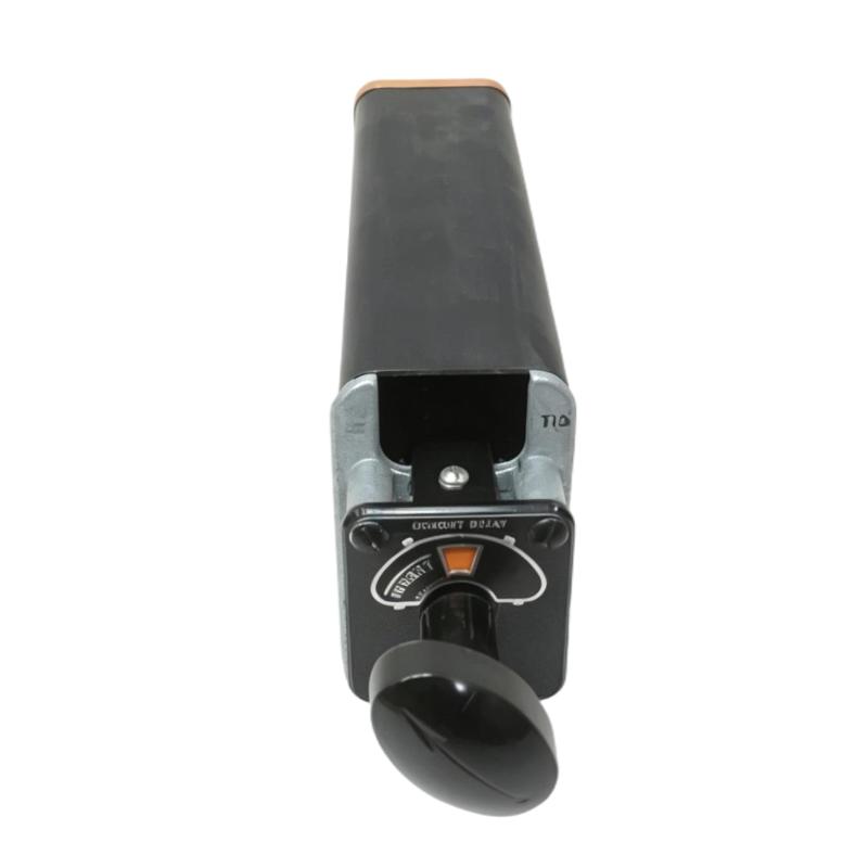
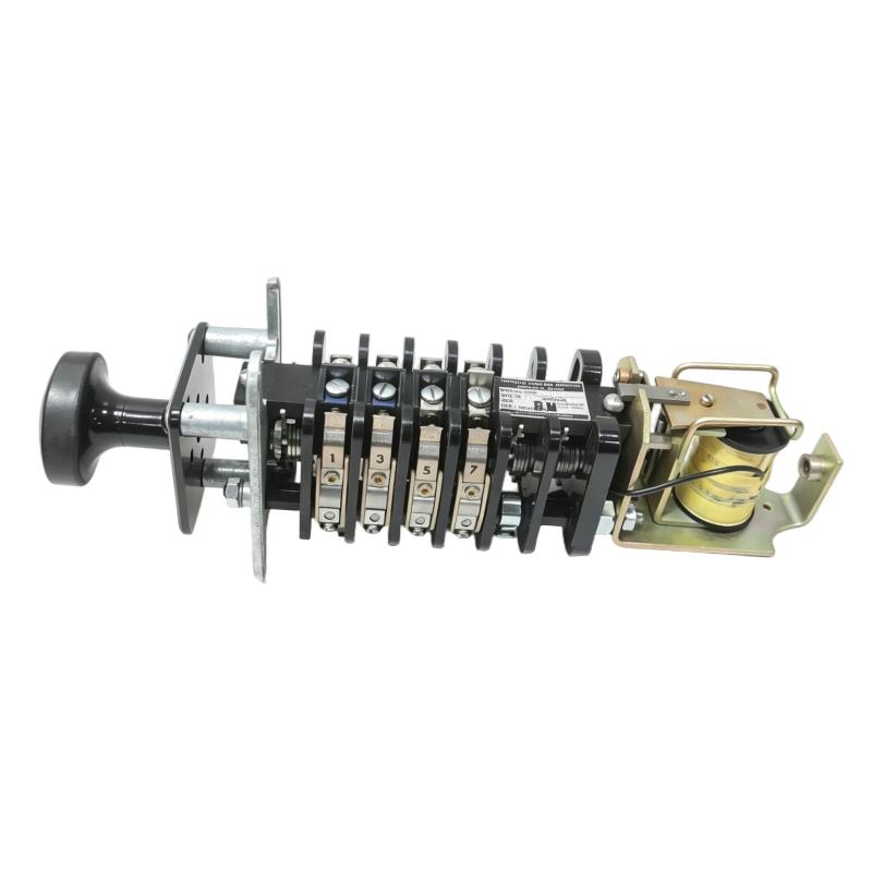
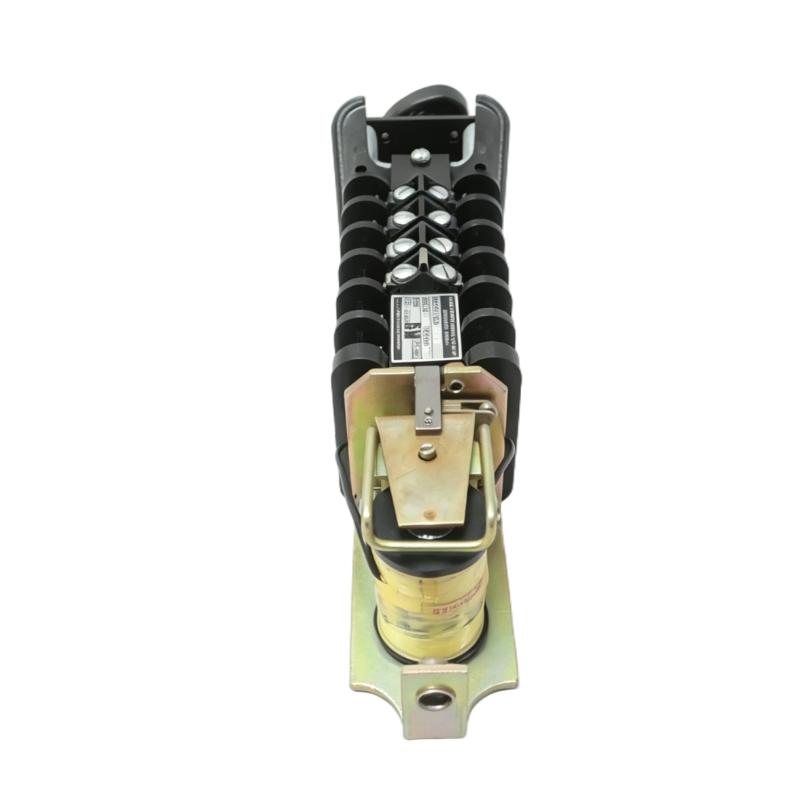
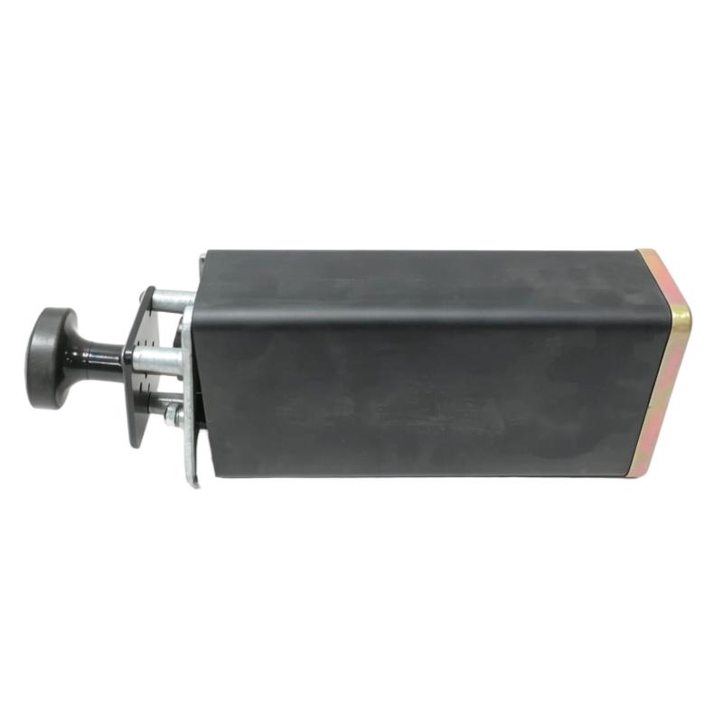
- GE
- 12HEA61A222X2
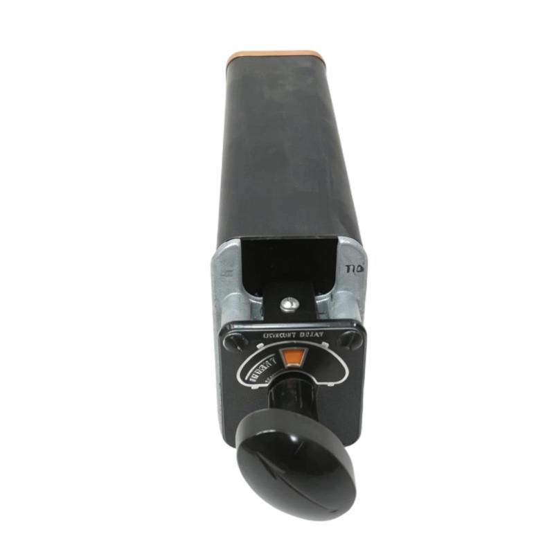
- HEA Lockout Relay
- USA
- 320 × 55 × 150 mm
- 1.7 kg
- Xiamen, China
- New & In Stock
- T/T, PayPal, Western Union
- 1 Year
- 1-3 Working Days
- DHL, UPS, TNT, FedEx and EMS.
- 24-Hour Service
- COO
- 5
Our advantage

Global Logistics
We have a 10-year logistics and express cooperation agreement, so our products can be shipped to any place in the world.

Brand new and original
Our products are imported in bulk from the place of origin. Because of the cooperative relationship, our products are all original and 100% new.

24-hour service
We provide 7*24 hours service to our customers. We will be there whenever you need us.

Price advantage
All our products are priced very favorably because we have our own warehouse and supply.
| Company Information | |||
| [email protected] | |||
| Mobile | +8615980777398 | ||
| +8615980777398 | |||
| 15980777398 |
Product Overview
The GE 12HEA61A222X2 is an HEA Lockout Relay used in electrical control and protection circuits where a tripped or abnormal condition needs to initiate a defined lockout action. Rather than serving as a general-purpose PLC output device, a lockout relay forms part of the protection and interlocking path, helping prevent equipment from returning to operation until the initiating condition has been investigated and the appropriate reset procedure has been completed.
In industrial switchgear and control applications, the relay can be associated with protection trips, breaker control circuits, equipment interlocks, or other conditions requiring a maintained lockout state. Its contacts can be incorporated into the surrounding control logic so that a trip signal affects downstream permissives, annunciation, or equipment operation.
The HEA designation places the device within GE’s relay product family, making it particularly relevant to existing control and protection assemblies that use HEA-series relay components.
Technical Specifications
| Parameter | Specification |
|---|---|
| Product Model | 12HEA61A222X2 |
| Product Type | HEA Lockout Relay |
| Series | HEA |
| Relay Function | Lockout / Protection Control |
| Dimensions | 320 × 55 × 150 mm |
| Weight | 1.7 kg |
Product Features
- Lockout relay function — Maintains a defined protection or trip condition within the associated control circuit.
- Protection circuit integration — Can be incorporated into equipment trip, interlock, and permissive circuits.
- Contact-based control — Uses relay contacts to transfer the lockout state to connected control circuitry.
- Reset-oriented operation — Supports control schemes where equipment remains inhibited until a defined reset action is performed.
- HEA relay family construction — Suited to control assemblies built around GE HEA-series relay components.
- Industrial protection application — Appropriate for electrical equipment where a trip condition must be clearly separated from ordinary control commands.
Working Principle
The 12HEA61A222X2 operates as part of a protection or lockout circuit. When the associated trip condition is detected, the relay changes the state of its contacts according to the configured control circuit. Those contacts can then interrupt a permissive path, initiate an alarm, block a control command, or pass the trip condition to another protection or control device.
The important distinction is that a lockout relay is normally used to preserve the consequences of a protection event rather than simply produce a momentary switching signal. Once the equipment has entered the lockout condition, the surrounding circuit determines how the relay is reset and when normal operation can be permitted again.
For troubleshooting, technicians typically trace the circuit from the initiating protection contact through the lockout relay and onward to the breaker, contactor, annunciator, or control system. This makes contact condition and wiring continuity important parts of maintenance testing.
Role in a GE HEA Protection and Control Architecture
| Architecture Layer | Role of 12HEA61A222X2 |
|---|---|
| Protection Device | Detects the electrical or equipment condition requiring a trip |
| Trip Circuit | Carries the initiating protection command toward the lockout circuit |
| 12HEA61A222X2 | Changes and maintains the required lockout relay contact state |
| Interlock / Permissive Circuit | Uses the relay contacts to prevent unauthorized re-energization |
| Breaker or Contactor Control | Receives the resulting trip or blocking command |
| Alarm / Indication Circuit | Can use associated contacts to indicate the lockout condition |
| Reset Circuit | Provides the defined path for returning the relay to its normal operating state |
The relay therefore acts as an intermediate protection-control element between the initiating trip condition and the equipment control circuit. Its value is in maintaining the intended protection logic rather than directly performing the primary switching function of the protected equipment.
Industrial Applications
| Application | Typical Use |
|---|---|
| Switchgear Protection | Maintaining a trip or lockout condition following a protection event |
| Circuit Breaker Control | Blocking closing commands until the lockout condition is cleared |
| Motor Protection Systems | Interlocking equipment after a defined protective trip |
| Generator Control | Incorporating protection trips into breaker and permissive circuits |
| Industrial Power Distribution | Connecting protection signals with control and annunciation circuits |
| Equipment Interlocking | Preventing operation while a specified fault or trip condition remains active |
| Retrofit Control Panels | Replacing or maintaining relay functions in existing GE-based protection assemblies |
Installation and Maintenance
- Confirm the relay application — Verify that the HEA lockout relay matches the protection and control function specified for the equipment.
- Review the circuit diagram — Identify the initiating trip contacts, relay terminals, downstream contacts, and reset path before installation.
- Isolate the control circuit — De-energize the relevant circuit and follow the site’s electrical safety procedure before handling the relay.
- Verify relay identification — Check the model marking against the equipment documentation before installation.
- Inspect terminal wiring — Look for loose connections, damaged conductors, corrosion, or signs of overheating.
- Check contact condition — Inspect the relay contacts for abnormal wear, contamination, or evidence of excessive electrical stress.
- Verify the trip path — Confirm that the initiating protection signal reaches the intended relay circuit.
- Test the lockout action — Under controlled conditions, verify that the relay changes state correctly when the associated trip condition is applied.
- Check downstream interlocks — Confirm that breaker, contactor, permissive, and alarm circuits respond as expected.
- Test the reset circuit — Verify that the relay cannot be reset incorrectly and that the intended reset sequence restores the correct control state.
- Investigate repeated lockouts — Do not treat repeated relay operation as a relay fault until the initiating protection condition has been checked.
- Document maintenance work — Record relay replacement, wiring changes, contact tests, and protection-circuit modifications in the equipment documentation.
Compatible System Components
| Component | Relationship |
|---|---|
| GE HEA Relay Assemblies | Related relay components within the same product family |
| Protection Relays | Provide the initiating trip or protective condition |
| Circuit Breaker Control Circuits | Use lockout contacts to block or permit breaker operation |
| Contactor Control Circuits | Can receive interlock or trip commands through relay contacts |
| Annunciator Circuits | Provide visual or audible indication of a lockout condition |
| Reset / Permissive Circuits | Define how the equipment can return from the lockout state |
Recommended Related Models
| Model | Product Type | Application Relationship |
|---|---|---|
| GE 12HEA61A222X2 | HEA Lockout Relay | Lockout and protection control function |
| GE HEA Relay Series | HEA Relay | Related relay family for electrical control applications |
| GE Protection Relay Assemblies | Protection Relay | Associated equipment for initiating protective trip conditions |
| GE Breaker Control Relays | Control Relay | Related components for breaker trip and closing circuits |
| GE Auxiliary Relay Assemblies | Auxiliary Relay | Used for contact multiplication and control-circuit interlocking |
Key Advantages
- Maintains a defined lockout state following a protection event.
- Integrates relay contacts into breaker, contactor, interlock, and alarm circuits.
- Separates protection-trip logic from ordinary equipment control commands.
- Supports structured troubleshooting through the protection and control circuit.
- Fits applications where controlled reset is required before equipment operation can resume.
- Suitable for maintenance and retrofit work involving GE HEA relay-based assemblies.
Technical FAQs
What is the primary function of the GE 12HEA61A222X2?
The 12HEA61A222X2 is an HEA Lockout Relay used to maintain a defined trip or lockout condition within an electrical protection and control circuit. Its contacts can be incorporated into interlock, permissive, breaker-control, or annunciation circuits.
Why is a lockout relay used instead of an ordinary control relay?
A lockout relay is used when the protection scheme needs a defined maintained state after a trip event. The surrounding control circuit can then require investigation and an intentional reset before the protected equipment is allowed to return to normal operation.
Can the 12HEA61A222X2 directly trip a circuit breaker?
The relay itself is normally part of the breaker protection and control circuit rather than the primary interruption mechanism. Its contacts can initiate or block the appropriate breaker-control functions, while the breaker performs the actual power interruption.
What should be checked when a lockout relay does not reset?
First verify the initiating protection condition and the reset circuit. Then check relay contact state, terminal wiring, interlocks, and downstream permissive circuits. If the initiating trip condition is still present, replacing the relay alone may not clear the lockout.