

ProductPRODUCT
Featured products
Contact Us
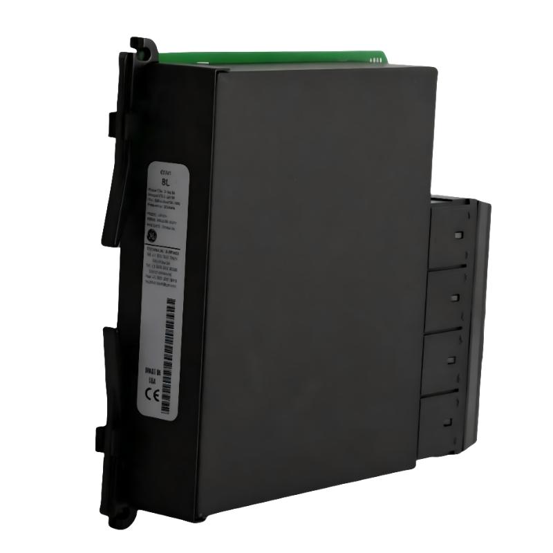
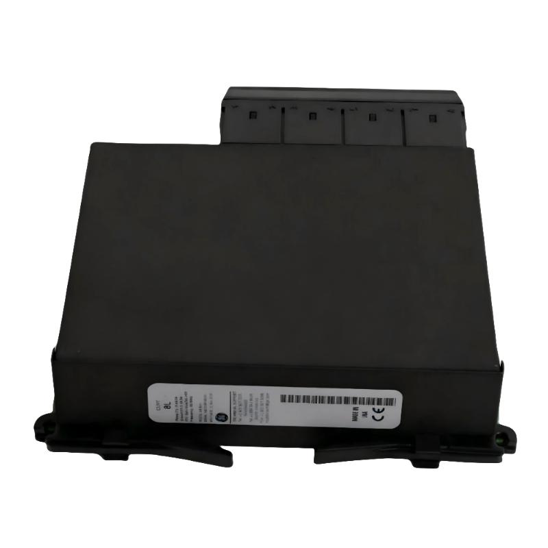
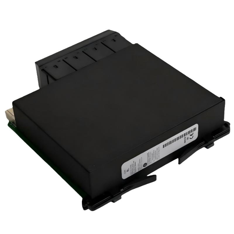
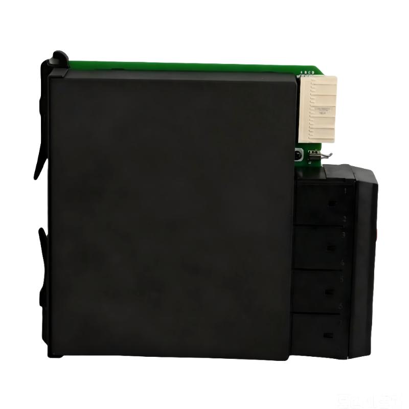
- GE
- UR 8FV
- CT/VT Module
- USA
- 120 × 30 × 100 mm
- 1.18 kg
- Xiamen, China
- New & In Stock
- T/T, PayPal, Western Union
- 1 Year
- 1-3 Working Days
- DHL, UPS, TNT, FedEx and EMS.
- 24-Hour Service
- COO
- 4
Our advantage

Global Logistics
We have a 10-year logistics and express cooperation agreement, so our products can be shipped to any place in the world.

Brand new and original
Our products are imported in bulk from the place of origin. Because of the cooperative relationship, our products are all original and 100% new.

24-hour service
We provide 7*24 hours service to our customers. We will be there whenever you need us.

Price advantage
All our products are priced very favorably because we have our own warehouse and supply.
| Company Information | |||
| [email protected] | |||
| Mobile | +8615980777398 | ||
| +8615980777398 | |||
| 15980777398 |
Product Overview
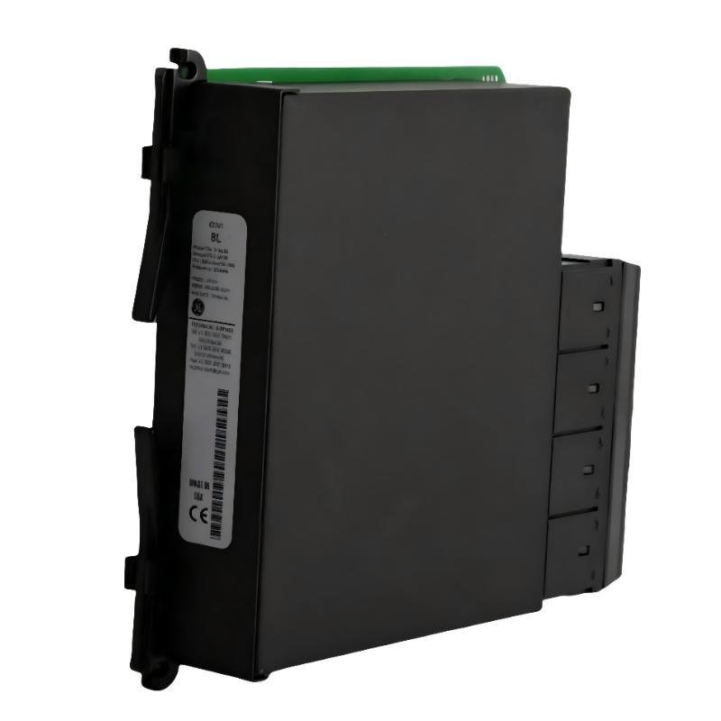
The GE UR 8FV is a Multilin UR Series CT/VT Module used to interface current transformer and voltage transformer signals with a GE Multilin Universal Relay system. It forms part of the measurement input chain between the electrical system’s instrument transformers and the relay’s internal protection and monitoring functions.
In a feeder, generator, motor, or switchgear application, CT and VT circuits provide scaled representations of system current and voltage. The UR 8FV receives these measurement signals so the host UR relay can use them for protection calculations, metering, event analysis, supervision, and control logic.
For maintenance work, the module should be considered together with the associated CT/VT wiring and relay configuration. Phase assignment, signal routing, and configuration all affect the measurements available to the protection system.
Technical Specifications
| Parameter | Specification |
|---|---|
| Product Model | UR 8FV |
| Product Type | Multilin UR Series CT/VT Module |
| Series | Multilin UR |
| I/O Function | CT / VT Signal Interface |
| Dimensions | 120 × 30 × 100 mm |
| Weight | 1.18 kg |
Product Features
- CT/VT measurement interface — Connects current and voltage transformer circuits with the Multilin UR relay.
- Electrical signal acquisition — Provides the relay with current and voltage information from the protected system.
- Multilin UR integration — Fits the modular I/O structure of the Universal Relay platform.
- Protection measurement support — Supplies measurement information used by configured protection functions.
- Metering and monitoring interface — Allows the relay to use CT/VT information for electrical monitoring and event analysis.
- Application-specific modularity — Supports UR relay configurations that require dedicated CT/VT measurement inputs.
Working Principle
The UR 8FV receives current and voltage signals from the external instrument-transformer circuits. These signals are routed through the module into the host Multilin UR relay, where the measured electrical quantities become available to the relay’s configured protection and monitoring functions.
The relay can use the measurements to evaluate electrical operating conditions and execute functions appropriate to the application. For example, current information may be used by protection elements, while voltage information can support voltage supervision, measurement, and other control functions.
Correct signal routing is essential. A fault in the external CT/VT circuit, an incorrect phase connection, or an incorrect relay configuration can produce abnormal measurements even when the I/O module is functioning correctly. Commissioning therefore normally includes verification of the complete measurement path.
Role in a GE Multilin UR Protection and Measurement Architecture
| Architecture Layer | Role of UR 8FV |
|---|---|
| Protected Electrical System | Provides the current and voltage conditions being monitored |
| Current Transformers | Produce scaled current signals |
| Voltage Transformers | Produce scaled voltage signals |
| CT/VT Wiring | Carries measurement signals to the relay |
| UR 8FV | Provides the CT/VT interface within the UR platform |
| Multilin UR Relay | Processes the received electrical measurements |
| Protection / Monitoring Logic | Uses the measurements for configured functions |
| SCADA / HMI | Presents relay measurements and status information |
The UR 8FV occupies the measurement interface layer of the system. It does not replace the host relay’s protection processor; instead, it provides the electrical measurement path required by that processor.
Industrial Applications
| Application | Typical Use |
|---|---|
| Feeder Protection | Supplying current and voltage measurements to a UR feeder relay |
| Generator Protection | Providing electrical measurements for generator protection and monitoring |
| Motor Protection | Connecting motor-side CT/VT signals to the relay platform |
| Switchgear Protection | Integrating instrument-transformer circuits with relay protection |
| Substation Automation | Supporting relay-based measurement and protection functions |
| Industrial Power Distribution | Monitoring electrical conditions within industrial distribution systems |
| Electrical Equipment Monitoring | Providing measurement information for relay supervision and analysis |
Installation and Maintenance
- Confirm the module application — Verify that the UR 8FV matches the required CT/VT interface for the host Multilin UR relay configuration.
- Review the protection drawings — Identify the source of each current and voltage signal and its corresponding relay channel.
- Apply instrument-transformer safety procedures — Follow the site’s approved procedures before working on CT or VT circuits.
- Verify module identification — Check the module designation against the equipment documentation before installation.
- Inspect external wiring — Look for loose terminals, damaged conductors, incorrect phase connections, or signs of overheating.
- Check module seating — Verify that the module is properly installed and that its interface connections are secure.
- Verify phase assignment — Confirm that current and voltage channels correspond to the intended system phases.
- Check polarity and continuity — Verify the measurement circuits against the approved protection drawings and commissioning procedure.
- Compare measured values — Check relay readings against expected current and voltage conditions.
- Trace abnormal signals — If measurements are incorrect, inspect the CT/VT source, wiring, module interface, and relay configuration in sequence.
- Perform functional testing — Confirm that the relay correctly receives and processes the expected measurement signals.
- Document maintenance activity — Record module replacement, wiring changes, configuration updates, and test results.
Compatible System Components
| Component | Relationship |
|---|---|
| GE Multilin UR Protection Relays | Host platform for the CT/VT module |
| Current Transformers | Provide current measurement signals |
| Voltage Transformers | Provide voltage measurement signals |
| GE Multilin UR I/O Modules | Related modules used to configure relay interfaces |
| Protection Test Equipment | Used to verify CT/VT input channels during commissioning |
| SCADA / HMI Systems | Use relay measurements for monitoring and supervision |
| Switchgear Control Systems | Operate alongside the relay in integrated protection architectures |
Recommended Related Models
| Model | Product Type | Application Relationship |
|---|---|---|
| GE UR 8FV | Multilin UR Series CT/VT Module | CT/VT measurement interface for UR relay systems |
| GE UR 8AH | Multilin UR Series CT/VT Module | Related CT/VT interface module within the UR platform |
| GE Multilin UR CT/VT Modules | CT/VT Input Module | Related measurement interface options for Universal Relay systems |
| GE Multilin UR Feeder Relays | Feeder Protection Relay | Related UR platform for feeder protection applications |
| GE Multilin UR Generator Relays | Generator Protection Relay | Related UR platform for generator protection and monitoring |
Key Advantages
- Provides a dedicated CT/VT interface within the Multilin UR architecture.
- Connects instrument-transformer signals with relay protection and monitoring functions.
- Supports current and voltage measurement for application-specific relay configurations.
- Provides a defined signal path for commissioning and troubleshooting.
- Fits feeder, generator, motor, switchgear, and industrial power applications.
- Works as part of the modular I/O structure of GE Multilin UR systems.
Technical FAQs
What is the GE UR 8FV used for?
The UR 8FV is a Multilin UR Series CT/VT Module that interfaces external current and voltage transformer signals with a GE Multilin Universal Relay system.
What happens if the CT or VT phase assignment is incorrect?
The relay may display incorrect current or voltage relationships, which can affect measurement and protection functions. Phase assignment should therefore be verified against the protection drawings during commissioning and after module replacement.
How can an incorrect CT/VT measurement be diagnosed?
Start at the measurement source and trace the signal through the CT/VT wiring, module interface, and relay configuration. Comparing expected electrical values with the relay’s displayed measurements can help identify where the signal path differs from the intended configuration.
Is the UR 8FV itself a complete protection relay?
No. The UR 8FV is an I/O module that provides the CT/VT measurement interface. The host Multilin UR relay performs the configured protection, monitoring, metering, and control processing.