

ProductPRODUCT
Featured products
Contact Us
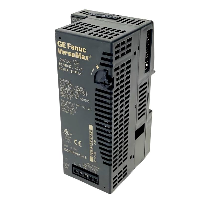
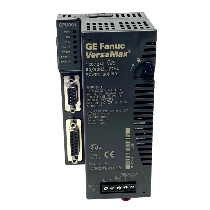
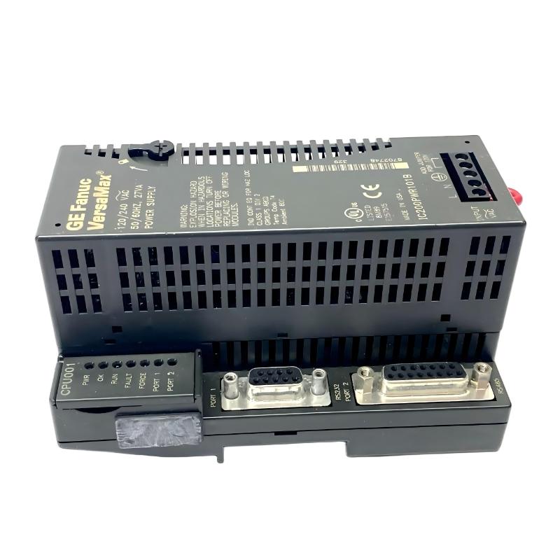
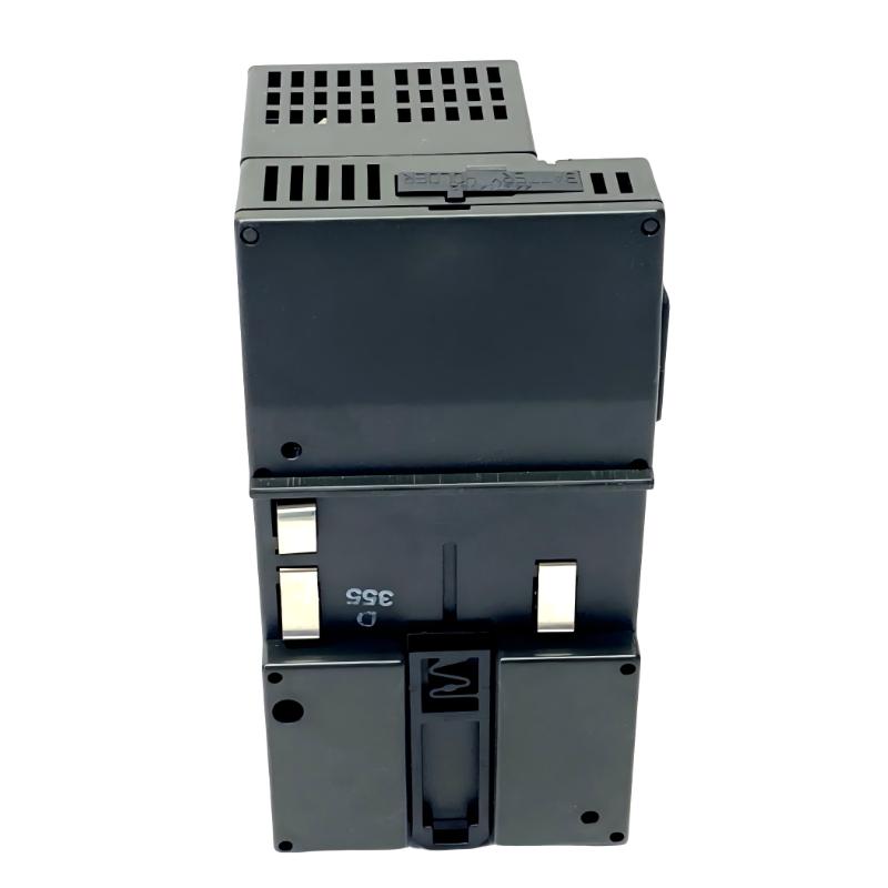
- GE
- IC200PWR101B
- VersaMax Power Supply Module
- USA
- 133.4 × 39 × 49 mm
- 0.25 kg
- Xiamen, China
- New & In Stock
- T/T, PayPal, Western Union
- 1 Year
- 1-3 Working Days
- DHL, UPS, TNT, FedEx and EMS.
- 24-Hour Service
- COO
- 57
Our advantage

Global Logistics
We have a 10-year logistics and express cooperation agreement, so our products can be shipped to any place in the world.

Brand new and original
Our products are imported in bulk from the place of origin. Because of the cooperative relationship, our products are all original and 100% new.

24-hour service
We provide 7*24 hours service to our customers. We will be there whenever you need us.

Price advantage
All our products are priced very favorably because we have our own warehouse and supply.
| Company Information | |||
| [email protected] | |||
| Mobile | +8615980777398 | ||
| +8615980777398 | |||
| 15980777398 |
Product Overview
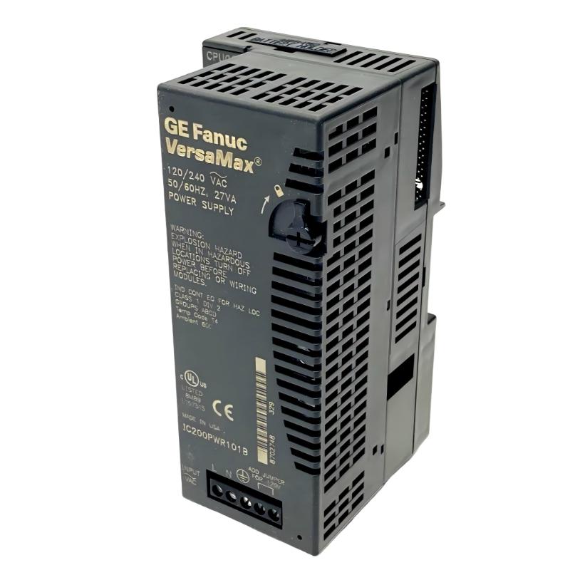
The GE IC200PWR101B VersaMax Power Supply Module is a power-supply component used within the GE VersaMax automation platform. Its job is to convert and distribute the required power for the VersaMax control hardware connected to the corresponding system architecture.
Unlike an I/O module, the IC200PWR101B does not primarily process field signals. It belongs to the power side of the control system. Its condition directly affects whether connected VersaMax modules can remain powered and operate as expected.
In a typical PLC installation, the power supply module works alongside the CPU, I/O modules, terminal assemblies, and backplane or carrier structure. The arrangement can be represented as:
Incoming Power → IC200PWR101B → VersaMax System → CPU / I/O Modules
This makes the module particularly relevant in applications where the PLC rack must maintain a consistent power source for control and I/O hardware.
A power-supply fault can sometimes appear to be a CPU or I/O problem. For example, unexpected module shutdown, loss of I/O operation, or intermittent controller behavior may originate from the power path rather than the logic hardware itself. For maintenance, engineers should therefore inspect the power supply, incoming wiring, module connections, and overall load condition before replacing other VersaMax components.
The IC200PWR101B is also relevant to replacement and refurbishment work on existing VersaMax installations where maintaining the original system architecture is preferable to redesigning the complete PLC assembly.
Technical Specifications
| Parameter | Specification |
|---|---|
| Manufacturer | GE |
| Model | IC200PWR101B |
| Product Family | VersaMax |
| Product Type | Power Supply Module |
| Primary Function | PLC System Power Supply |
| System Role | Power Interface |
| Application | Industrial Automation / PLC Control |
| Installation | GE VersaMax Control System |
| Dimensions | 133.4 × 39 × 49 mm |
| Weight | 0.25 kg |
Product Features
The IC200PWR101B serves the power requirements of a VersaMax control installation rather than performing direct signal processing.
- GE VersaMax Power Supply Module
- Model IC200PWR101B
- Used within VersaMax PLC architectures
- Supplies power to associated control hardware
- Interfaces with VersaMax CPU and I/O components
- Suitable for PLC control-panel installations
- Supports system-level power distribution
- Useful for existing VersaMax system maintenance
- Suitable for module replacement and refurbishment
- Compact form factor for control-panel integration
The actual power arrangement should be checked against the existing VersaMax configuration before replacement.
Working Principle
The IC200PWR101B sits at the power-entry side of the VersaMax control architecture.
A simplified relationship is:
Power Source → Power Supply Module → VersaMax Hardware
The incoming electrical supply is connected to the power-supply section according to the applicable system configuration. The module then makes the required power available to the VersaMax control hardware.
The CPU and I/O modules depend on this power path to remain operational. If the supply becomes unavailable or falls outside the expected operating condition, downstream modules can lose power or exhibit abnormal behavior.
From a troubleshooting perspective, the sequence is therefore straightforward:
Incoming Supply → IC200PWR101B → System Power → CPU / I/O Operation
This is different from an I/O module, where the main task is to acquire or generate control signals. The power supply module instead establishes the electrical foundation on which those modules operate.
During maintenance, engineers should check the incoming supply and connections first. If the power source is correct but the VersaMax system remains inactive, the power-supply module and downstream distribution path can then be examined.
Role in a VersaMax PLC Architecture
The IC200PWR101B occupies the power-supply position within the VersaMax control system.
A simplified architecture is:
Incoming Power → IC200PWR101B → VersaMax CPU / Controller → I/O Modules → Field Devices
| System Element | Function |
|---|---|
| IC200PWR101B | Supplies system power |
| VersaMax CPU | Executes PLC logic |
| VersaMax I/O Modules | Interface with field signals |
| Terminal Assemblies | Connect field wiring |
| Backplane / Carrier Structure | Provides module interconnection |
| Input Modules | Acquire field conditions |
| Output Modules | Send commands to field devices |
| Programming / Engineering Interface | Used for PLC configuration |
| Field Devices | Provide or receive process signals |
| Control Panel | Houses and organizes PLC hardware |
The exact architecture depends on the specific VersaMax installation and module arrangement.
Power Supply and System Availability
A PLC power supply should be evaluated not only by whether its indicator appears normal, but also by the behavior of the complete control system.
For example, if several VersaMax I/O modules simultaneously become unavailable, the engineer should consider the common power path before treating every I/O module as an independent failure.
A practical diagnostic sequence can be:
1. Check Incoming Power
Verify that the expected supply reaches the power-input circuit.
2. Inspect the IC200PWR101B
Check the module condition, connections, and indicators where applicable.
3. Check System Connections
Inspect the connection between the power supply and the VersaMax hardware.
4. Observe CPU and I/O Status
Determine whether the controller and connected modules recover correctly.
5. Check the Downstream Load
If abnormal behavior remains, examine the connected modules and overall system loading.
This approach helps distinguish a common power problem from an individual I/O or controller fault.
Industrial Applications
| Application | Typical Use |
|---|---|
| Manufacturing | PLC control-panel power |
| Packaging Machinery | VersaMax controller systems |
| Material Handling | Conveyor and machine-control systems |
| Water Treatment | PLC-based control panels |
| Process Automation | Control and I/O hardware power |
| Machine Automation | CPU and I/O system support |
| Building Equipment | Automated equipment control |
| Industrial Production | VersaMax-based control systems |
Installation and Maintenance
Power-supply replacement requires attention to both electrical isolation and the existing PLC architecture.
Recommended practices include:
- Confirm the complete IC200PWR101B model.
- Verify the installed VersaMax system configuration.
- Record the existing power connections.
- Follow the approved electrical isolation procedure.
- Verify the incoming power condition.
- Inspect terminals and connectors.
- Check for loose or damaged conductors.
- Inspect the power-supply module for physical damage.
- Check the associated CPU and I/O modules.
- Review the system’s power-distribution arrangement.
- Confirm that the replacement module matches the existing application.
- Install the module according to the approved procedure.
- Restore power connections carefully.
- Check module and system status.
- Verify CPU operation.
- Check connected I/O modules.
- Confirm field-device communication.
- Test the PLC application.
- Monitor the system after restoration.
- Record the completed maintenance work.
If several modules lose operation simultaneously, investigate the common power path before replacing individual I/O modules.
Compatible System Components
The IC200PWR101B normally works as part of a broader VersaMax PLC assembly.
| Component | Function |
|---|---|
| GE IC200PWR101B | VersaMax Power Supply Module |
| VersaMax CPU | Executes control logic |
| VersaMax I/O Modules | Interfaces field signals |
| I/O Terminal Assembly | Provides field connection |
| Carrier / Backplane | Connects VersaMax modules |
| Discrete Input Module | Acquires ON/OFF field states |
| Discrete Output Module | Sends binary commands |
| Analog Input Module | Acquires process values |
| Analog Output Module | Sends analog control values |
| Programming Interface | Supports PLC configuration |
| Field Devices | Provide process inputs or receive commands |
Recommended Related Models
The following VersaMax models are commonly relevant when configuring or maintaining systems that combine power supply, discrete I/O, and analog signal processing.
| Model / Product Family | Product Type | Typical Application |
|---|---|---|
| GE IC200PWR101B | VersaMax Power Supply Module | PLC system power |
| GE IC200PWR102F | VersaMax Power Supply Module | VersaMax system power |
| GE IC200ALG230D | VersaMax Analog Input Module | Analog signal acquisition |
| GE IC200ALG321B | VersaMax Analog Input Module | Industrial analog inputs |
| GE IC200ALG442B | VersaMax Analog Input Module | Analog process monitoring |
| GE IC200MDL640 | VersaMax Discrete Input Module | Discrete field-state acquisition |
| GE VersaMax CPU Modules | VersaMax Controller | PLC logic execution |
Key Advantages
- GE VersaMax Power Supply Module.
- Model IC200PWR101B.
- Supports power requirements of VersaMax control hardware.
- Suitable for PLC CPU and I/O system architectures.
- Useful for control-panel maintenance.
- Applicable to VersaMax replacement projects.
- Helps maintain the power path for connected control modules.
- Suitable for existing industrial automation installations.
Technical FAQs
What is the primary function of the GE IC200PWR101B?
The IC200PWR101B serves as a power-supply module within the GE VersaMax control architecture. Its role is to establish the required power path for associated VersaMax control and I/O hardware rather than process field signals directly.
Why can a power-supply problem look like an I/O or CPU failure?
The CPU and I/O modules depend on the system power path. If the power supply or its connections become unavailable, multiple downstream modules may stop operating at the same time. This can make the problem appear to involve several individual modules when the common cause is actually the power system.
What should be checked if multiple VersaMax modules stop operating together?
Start with the incoming supply and the IC200PWR101B power path. Then inspect terminals, connectors, system connections, and the condition of the CPU and I/O modules. A simultaneous loss of several modules is a strong reason to investigate common power distribution before replacing individual I/O hardware.
What should be verified before replacing an IC200PWR101B?
Engineers should confirm the complete model number, existing VersaMax architecture, incoming power arrangement, module connections, and installation requirements. After replacement, system power, CPU operation, I/O availability, and the connected PLC application should all be checked.