

ProductPRODUCT
Featured products
Contact Us
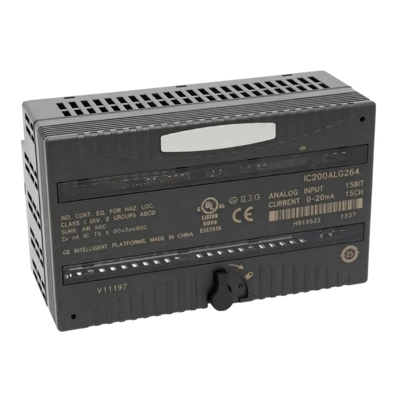
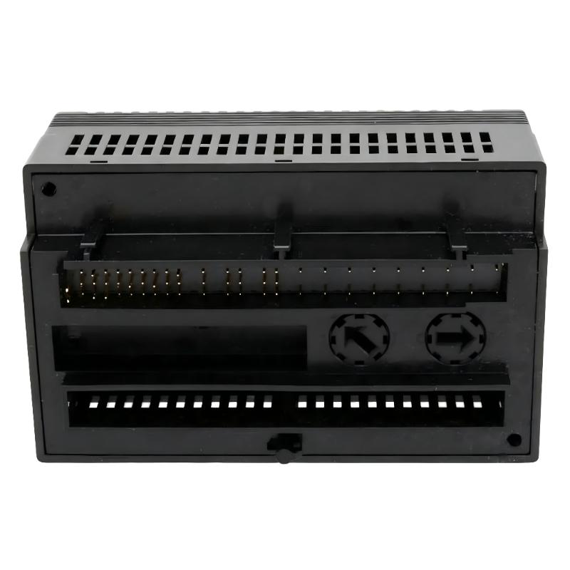
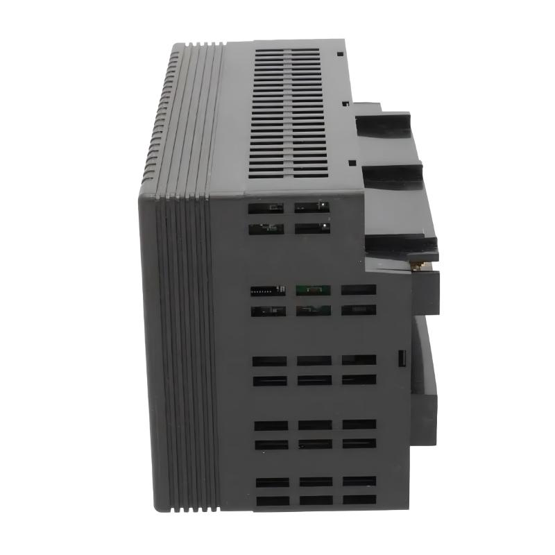
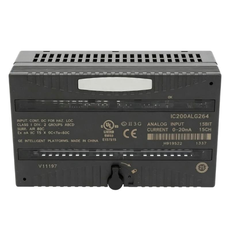
- GE
- IC200ALG264H
- Analog Input Module
- USA
- 110 × 66.8 × 50 mm
- 0.91 kg
- Xiamen, China
- New & In Stock
- T/T, PayPal, Western Union
- 1 Year
- 1-3 Working Days
- DHL, UPS, TNT, FedEx and EMS.
- 24-Hour Service
- COO
- 5
Our advantage

Global Logistics
We have a 10-year logistics and express cooperation agreement, so our products can be shipped to any place in the world.

Brand new and original
Our products are imported in bulk from the place of origin. Because of the cooperative relationship, our products are all original and 100% new.

24-hour service
We provide 7*24 hours service to our customers. We will be there whenever you need us.

Price advantage
All our products are priced very favorably because we have our own warehouse and supply.
| Company Information | |||
| [email protected] | |||
| Mobile | +8615980777398 | ||
| +8615980777398 | |||
| 15980777398 |
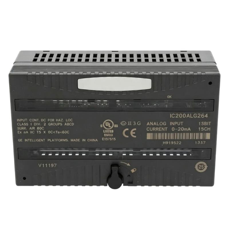
Product Overview
The GE IC200ALG264H is a VersaMax Analog Input Module used to acquire analog signals from field instruments and make those measurements available to the PLC control system. It is intended for applications where process variables need to be monitored as continuously changing values rather than simple ON/OFF states.
Typical field signals can represent pressure, temperature, flow, level, position, or other process measurements, depending on the connected instrumentation and application configuration. The module converts the incoming analog signal into information that the VersaMax controller can use for monitoring, control calculations, alarm handling, and process sequencing.
In a process-control cabinet, the IC200ALG264H can be connected to transmitters and other analog field devices associated with pumps, valves, tanks, production equipment, and utility systems. The PLC application can then use the acquired values for closed-loop control, operator displays, limit monitoring, or data collection.
For maintenance work, engineers should verify the module model, signal type, channel assignment, field wiring, termination arrangement, and PLC configuration before replacement. An incorrect analog reading can result from the field instrument, wiring, signal configuration, input channel, or scaling parameters rather than the module itself.
Technical Specifications
| Parameter | Specification |
|---|---|
| Manufacturer | GE |
| Model | IC200ALG264H |
| Product Family | VersaMax |
| Product Type | Analog Input Module |
| Primary Function | Analog Field Signal Acquisition |
| System Role | PLC Analog Input Interface |
| Application | Industrial Automation / Process Control |
| Installation | GE VersaMax PLC System |
| Dimensions | 110 × 66.8 × 50 mm |
| Weight | 0.91 kg |
Product Features
The IC200ALG264H is used for analog signal acquisition within a GE VersaMax control architecture.
Key characteristics include:
- GE VersaMax Analog Input Module
- Model IC200ALG264H
- Acquires continuously varying field signals
- Interfaces analog instrumentation with the PLC system
- Suitable for process-variable monitoring
- Applicable to measurement and control applications
- Useful for pressure, temperature, flow, level, and other analog process signals
- Supports PLC-based process monitoring and control
- Suitable for manufacturing and process automation
- Useful for existing VersaMax system maintenance and replacement
The module should be matched to the actual field signal requirements and VersaMax configuration. Signal type, channel assignment, wiring, and software scaling should be checked before commissioning.
Working Principle
The IC200ALG264H receives analog electrical signals from connected field instruments and converts the measured signal into digital information that can be processed by the VersaMax PLC.
Field Transmitter → IC200ALG264H → VersaMax PLC → Control Application
The operating process includes:
-
Process Measurement
A field transmitter or analog instrument measures a physical variable such as temperature, pressure, flow, or level.
-
Analog Signal Transmission
The instrument sends the corresponding electrical signal through the field wiring to the analog input module.
-
Signal Acquisition
The IC200ALG264H receives the analog input and converts the electrical measurement into a digital value for the control system.
-
PLC Processing
The VersaMax controller reads the acquired value and applies the configured application logic.
-
Process Response
The PLC can use the value for control calculations, alarm conditions, operator displays, equipment regulation, or process monitoring.
A typical application relationship is:
Physical Variable → Analog Signal → Input Module → PLC Value → Control / Monitoring
Role in a VersaMax PLC Architecture
The IC200ALG264H occupies the analog-input layer of the VersaMax control system.
Field Instrumentation → IC200ALG264H → VersaMax Controller → HMI / Control Logic
| System Element | Function |
|---|---|
| IC200ALG264H | Acquires analog field measurements |
| VersaMax CPU | Processes application logic and acquired values |
| VersaMax I/O System | Provides the PLC field-interface structure |
| Analog Transmitters | Measure process variables and generate analog signals |
| Field Wiring | Carries analog signals to the input module |
| HMI | Displays process measurements and equipment conditions |
| Control Logic | Uses analog values for regulation, alarms, and sequences |
| Engineering Workstation | Supports configuration, diagnostics, and maintenance |
Industrial Applications
| Application | Typical Use |
|---|---|
| Process Control | Monitoring continuously changing process variables |
| Water Treatment | Measuring flow, level, pressure, and other plant conditions |
| Chemical Processing | Acquiring process measurements for control and monitoring |
| Manufacturing | Monitoring production-process variables |
| Pump Systems | Measuring operating conditions for pump control |
| HVAC and Utilities | Monitoring temperature, pressure, and other operating values |
| Material Processing | Tracking process variables during production |
| Machine Automation | Acquiring analog measurements for machine control |
The actual application depends on the connected instrumentation, configured signal arrangement, and VersaMax control program.
Installation and Maintenance
- Confirm the complete IC200ALG264H model before installation or replacement.
- Check the existing VersaMax hardware and I/O configuration.
- Identify each field instrument connected to the analog input channels.
- Record channel assignments and existing signal configuration.
- Inspect field wiring for loose terminals, damaged conductors, or incorrect connections.
- Verify the signal type and electrical characteristics required by the application.
- Install the module according to the approved VersaMax maintenance procedure.
- Confirm that the PLC recognizes the installed analog input hardware.
- Check the raw input value before applying software scaling or engineering-unit conversion.
- Compare the PLC reading with the expected field-instrument measurement.
- Check scaling, alarm limits, and application logic after the input value has been confirmed.
- Review controller diagnostics if a channel shows an unexpected or unstable reading.
- Record the final channel configuration for future maintenance.
An incorrect analog value should be traced through the field instrument, wiring, input channel, configuration, scaling, and PLC application before replacing the module.
Related Components
| Component | Function |
|---|---|
| GE IC200ALG264H | VersaMax Analog Input Module |
| VersaMax CPU | Executes PLC application logic |
| VersaMax Power Supply | Supplies power to the control system |
| VersaMax I/O Components | Provide additional field interfaces |
| Analog Transmitter | Generates process measurement signals |
| Pressure / Temperature Instruments | Provide process-variable measurements |
| HMI | Displays acquired analog values |
| Engineering Workstation | Supports configuration and diagnostics |
| Field Wiring | Carries analog signals between instruments and I/O |
Recommended Related Models
| Model / Product Family | Product Type | Typical Application |
|---|---|---|
| GE IC200ALG Series | VersaMax Analog I/O Modules | Analog field signal acquisition |
| GE IC200MDL Series | VersaMax Discrete I/O Modules | Digital field signal handling |
| GE IC200CPU Series | VersaMax CPU Module | PLC control and application execution |
| GE IC200PWR Series | VersaMax Power Supply | PLC system power |
| GE VersaMax I/O System | PLC I/O Platform | Machine and process automation |
| GE VersaMax Communication Modules | Communication Modules | PLC networking and data exchange |
Key Advantages
- GE VersaMax Analog Input Module.
- Model IC200ALG264H.
- Provides analog field-signal acquisition for VersaMax PLC systems.
- Suitable for continuously varying process measurements.
- Useful for monitoring pressure, temperature, flow, level, and similar variables.
- Supports PLC-based process-control applications.
- Suitable for manufacturing and industrial automation.
- Useful for maintenance and replacement of existing VersaMax I/O systems.
Technical FAQs
What type of signals can the GE IC200ALG264H be used to acquire?
The IC200ALG264H is intended for analog input acquisition from compatible field instrumentation. Typical applications involve continuously varying process measurements such as pressure, temperature, flow, level, or position, with the exact signal arrangement determined by the installed system configuration.
Why is signal scaling important when commissioning the IC200ALG264H?
The PLC receives an input value that must correspond correctly to the engineering value used by the control application. Incorrect scaling can make a normal field measurement appear too high, too low, or otherwise incorrect even when the physical signal reaching the input channel is valid.
How can an engineer distinguish a faulty analog input channel from a field-instrument problem?
The signal should be checked progressively from the field instrument through the wiring and terminal connection to the input channel. Comparing the physical signal with the PLC’s raw input value can help determine whether the problem originates in the instrument, field wiring, I/O channel, or software configuration.
What should be verified after replacing an IC200ALG264H?
The input channel assignments, field-signal configuration, raw input values, engineering-unit scaling, alarm limits, and related PLC logic should be checked. Representative field measurements should also be compared with the values displayed by the control application before returning the system to normal operation.