
NewsNEWCENTER
Featured products

Contact Us
GE Fanuc IC693ALG223D Analog Input Module Installation and Commissioning Guide
2026-10-20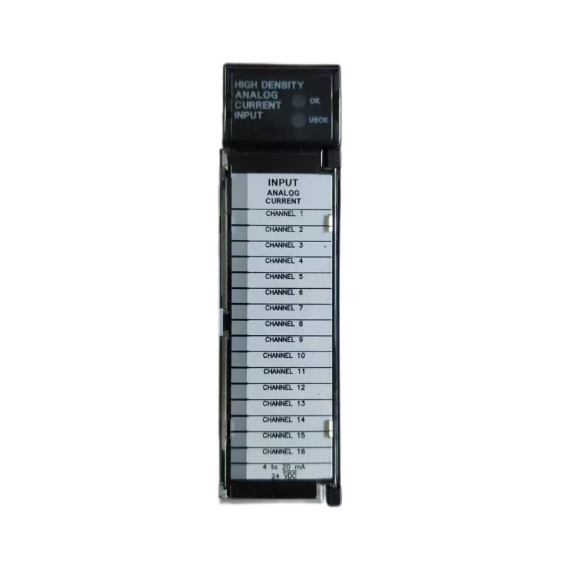
The GE Fanuc IC693ALG223D Analog Input Module is a high-density analog current input module designed for the Series 90-30 PLC platform. It enables industrial controllers to receive current signals from field instruments, transmitters, process sensors, and other compatible devices, converting these signals into digital values for monitoring, control, and automation applications.
The IC693ALG223D supports 16 single-ended current input channels and is designed for signals including 0–20 mA, 4–20 mA, and an enhanced 4–20 mA range with open-wire detection. Correct installation requires attention to rack compatibility, external power requirements, field wiring, current-loop configuration, signal scaling, and commissioning procedures. This guide explains the practical steps required to install and integrate the module safely into an industrial control system.
Table of Contents
- Product Overview
- Technical Specifications
- Installation Preparation
- PLC Rack Installation
- Field Wiring and Current-Loop Connections
- PLC Configuration
- Startup and Commissioning
- System Integration
- Maintenance and Inspection
- Frequently Asked Questions
- Technical Summary
1. Product Overview
The IC693ALG223D belongs to the GE Fanuc Series 90-30 programmable logic controller family. Its primary function is to acquire analog current signals from field devices and make the corresponding process measurements available to the PLC CPU.
Typical applications include pressure monitoring, temperature transmitter measurement, flow measurement, level monitoring, and feedback from industrial process equipment. For example, a compatible pressure transmitter may provide a 4–20 mA signal representing a configured pressure range. The analog input module reads that signal, and the PLC program converts the resulting input value into engineering units.
The module is intended for integration into a compatible Series 90-30 rack. Before installation, verify the complete catalog number, hardware revision, baseplate compatibility, and system configuration. Although closely related catalog numbers may look similar, input types and electrical characteristics must not be assumed to be interchangeable.
2. Technical Specifications
| Parameter | Specification |
|---|---|
| Manufacturer | GE Fanuc |
| Product model | IC693ALG223D |
| Product type | Analog current input module |
| PLC platform | Series 90-30 |
| Number of input channels | 16 single-ended current inputs |
| Supported input ranges | 0–20 mA, 4–20 mA, enhanced 4–20 mA |
| Enhanced input function | Open-wire detection, subject to configuration and operating conditions |
| Input impedance | Approximately 250 ohms |
| Backplane current consumption | Approximately 120 mA at +5 V DC |
| External supply requirement | Nominal +24 V DC; verify the permitted range for the exact revision |
| External supply current | Approximately 65 mA, excluding field-loop current |
| Typical resolution information | Range-dependent; verify the exact module specification |
| Mounting | Compatible Series 90-30 baseplate slot |
| Primary function | Acquisition of analog current signals for PLC processing |
These values describe the IC693ALG223 module family and should be confirmed against the documentation applicable to the installed revision D. Do not infer exact terminal assignments, electrical isolation limits, update rate, or configuration behavior from another hardware revision.
3. Installation Preparation
3.1 Verify the Catalog Number
Check the module label and confirm that the installed hardware is marked IC693ALG223D. Record the revision, rack location, and existing system configuration. This is particularly important when replacing an older module or maintaining equipment that has been operating for many years.
3.2 Confirm Rack Compatibility
The IC693ALG223D is designed for the Series 90-30 platform. Verify that the PLC baseplate, CPU, power supply, available slot, and overall system configuration support the module. Consult the system hardware documentation to confirm slot restrictions and the maximum supported number of modules.
3.3 Review the Power Budget
The module draws approximately 120 mA from the +5 V DC backplane and requires an external +24 V DC supply for its specified operating functions. The complete system power budget must account for the CPU, other I/O modules, communication modules, and any additional loads connected to the external supply.
Do not assume that the PLC rack supply can provide all field transmitter loop current. Verify the field devices’ power requirements and determine whether a separate instrument power supply is needed.
3.4 Prepare the Installation Area
- Choose a clean, dry, and appropriately ventilated control cabinet.
- Confirm that the rack is securely mounted and accessible for maintenance.
- Keep analog signal cables away from high-current power conductors where practical.
- Prepare the approved field wiring diagram and PLC configuration backup.
- Check that the terminal assembly and connectors are compatible with the installed module.
3.5 Apply Electrical Safety Procedures
Before removing or installing the module, shut down the affected equipment according to the approved maintenance procedure. Isolate relevant power sources, apply lockout/tagout where required, and verify a safe electrical condition before touching terminals or rack connections.
Do not insert or remove the module under power unless the exact hardware and system documentation explicitly permits that operation. Never use a hot-swapping assumption based solely on the module’s appearance.
4. PLC Rack Installation
4.1 Inspect the Module
Before installation, inspect the module for physical damage, bent contacts, contamination, or signs of overheating. Confirm that its edge connector and mechanical guide features are in good condition.
If the module has been stored in a damp, dusty, or uncontrolled environment, evaluate its condition before placing it into service. Do not install equipment with visible corrosion or damaged electrical contacts.
4.2 Prepare the Baseplate Slot
Identify an approved I/O slot on the Series 90-30 baseplate. Confirm that the slot is available in the system configuration and that inserting the module will not interfere with neighboring components or cabinet wiring.
4.3 Insert the Module
- Confirm that the PLC system and associated power sources are in the required safe state.
- Align the module with the correct baseplate slot and mechanical guides.
- Insert the module evenly, avoiding excessive force or twisting.
- Ensure that the connector is fully seated and the retaining mechanism is secure.
- Inspect the surrounding rack area for loose hardware or displaced conductors.
- Restore any covers or protective components required by the installation.
Follow the applicable Series 90-30 installation instructions for the exact insertion and retention procedure. Do not force a module that does not align correctly.
4.4 Confirm Rack and CPU Compatibility
After physical installation, verify that the CPU and rack configuration can recognize the module. Review the PLC hardware configuration and the relevant diagnostic indicators according to the controller documentation.
If the module is not recognized, check the slot assignment, hardware configuration, connector seating, and system compatibility before attempting further operation.
5. Field Wiring and Current-Loop Connections
5.1 Identify the Correct Terminal Arrangement
Before wiring field instruments, obtain the terminal diagram for the exact IC693ALG223D revision and its compatible terminal assembly. Identify the channel input terminals, common or return connections, external supply connections, and any terminals that must remain unused.
Do not rely on terminal numbers from an unrelated Series 90-30 analog module. Incorrect wiring can damage equipment, produce invalid measurements, or create unsafe operating conditions.
5.2 Connect 4–20 mA Transmitters
A typical 4–20 mA measurement loop includes a compatible transmitter, an appropriate DC loop supply, and the analog input channel. The exact wiring depends on whether the transmitter is two-wire, three-wire, or externally powered.
Before making connections, establish whether the instrument is loop-powered or requires a separate power connection. Verify the transmitter’s supply rating, polarity, output type, and grounding requirements.
The following diagram is illustrative only and does not represent verified terminal assignments for the IC693ALG223D.
Illustrative current-loop arrangement

DC loop supply
     |
     v
Field transmitter
     |
     v
Analog input channel
     |
     v
Specified current return path

Use the exact module and transmitter wiring diagrams
to determine the actual terminal connections.
5.3 Connect 0–20 mA Signals
When using a 0–20 mA instrument, configure the corresponding input channel and PLC scaling logic for that range. Ensure that the instrument actually produces a 0–20 mA signal and that its output characteristics match the module’s requirements.
Do not select a 4–20 mA range for a 0–20 mA instrument without reviewing the effect on measurement scaling and fault interpretation. The configured range must correspond to the actual field signal.
5.4 Verify Polarity and Loop Continuity
Current-loop polarity and continuity are essential for reliable measurement. After isolating power, inspect the field wiring and terminal connections for reversed conductors, loose connections, damaged insulation, or interrupted return paths.
Check that the loop supply can support the transmitter’s required voltage and the total voltage drop across the field wiring and input circuit. If the loop cannot maintain adequate operating voltage, the measured current may be incorrect or absent.
5.5 Separate Analog and Power Wiring
Analog current signals can be affected by electrical noise generated by motor drives, contactors, switching power supplies, and other high-current equipment. Route analog cables separately from noisy power circuits where practical.
- Use cable types suitable for industrial instrumentation.
- Apply shielding and grounding according to the system design.
- Avoid unapproved grounding changes that could create ground loops.
- Keep cable routes protected from abrasion, heat, and mechanical damage.
- Label each channel and field device clearly.
6. PLC Configuration
6.1 Configure the Module in the PLC Project
Use the engineering software and hardware configuration appropriate for the installed Series 90-30 controller. Confirm the module type, rack location, slot assignment, and supported configuration options.
If the module is replacing an existing unit, preserve a backup of the current PLC program and hardware configuration before making changes. Compare the existing configuration with the installed module and investigate any mismatch.
6.2 Configure Input Ranges
Each channel must be configured or interpreted according to the signal range used by the connected instrument. Confirm whether the channel is intended for 0–20 mA, 4–20 mA, or the enhanced 4–20 mA mode, where supported by the exact revision.
Do not assume that every channel has the same configuration. Document the range associated with each transmitter and verify the module’s actual configuration method from the applicable technical instructions.
6.3 Scale Raw Values into Engineering Units
The PLC program normally converts the module’s raw input data into meaningful process values, such as bar, degrees Celsius, litres per minute, or percent level. Scaling parameters must match the transmitter’s calibrated measurement range and the module’s data representation.
For example, a transmitter configured for 0–10 bar may represent 0 bar at 4 mA and 10 bar at 20 mA. In that case, the program should map the valid current range to the corresponding pressure range rather than assuming that the current value directly represents pressure.
6.4 Configure Alarm Limits
Where supported by the installed module revision and PLC configuration, define appropriate high and low process limits in the control program. Distinguish process alarms from electrical faults such as an open current loop.
Alarm thresholds should reflect the process requirements, instrument range, and safety analysis. Do not use a single generic threshold for all channels without considering the function of each instrument.
7. Startup and Commissioning
7.1 Complete a Pre-Startup Inspection
- Verify the catalog number and revision.
- Confirm correct rack placement and secure module seating.
- Inspect field wiring and terminal connections.
- Verify external DC supply ratings and polarity.
- Confirm that every channel’s configured range matches its field instrument.
- Check that PLC scaling and alarm settings have been reviewed.
- Ensure that guards and other required safety devices are restored.
7.2 Restore Power in a Controlled Sequence
Restore power according to the approved startup procedure. Observe the PLC CPU and module diagnostic indicators, and check the controller’s hardware status. If a fault is reported, stop the commissioning sequence and investigate the cause before enabling process operation.
Do not assume that a module is functioning correctly solely because the PLC CPU enters RUN mode. The field signal paths and channel data must also be verified.
7.3 Test Representative Input Channels
Use a calibrated current source or an approved field-instrument test method to verify representative channels. Test values should remain within the permitted range and should be applied using the correct connection procedure.
Compare the input current with the raw value reported by the PLC and the engineering-unit value calculated by the application program. Confirm that the displayed measurement changes in the expected direction and by the expected amount.
7.4 Verify the Full Measurement Loop
Where practical, verify each critical measurement from the field transmitter through the module and PLC program to the operator display or supervisory system.
- Apply a known input or use a calibrated instrument reference.
- Confirm that the field loop produces the expected current.
- Verify that the module data changes as expected.
- Check the PLC scaling calculation.
- Confirm the displayed engineering value and alarm behavior.
- Record the test result and any deviations.
7.5 Record Commissioning Data
Document the module revision, rack and slot, channel assignments, transmitter ranges, loop supply arrangements, scaling parameters, alarm limits, and test results. These records simplify future maintenance and help distinguish module faults from field-instrument problems.
8. Integration with Industrial Control Systems
8.1 Process Instrumentation
The IC693ALG223D can support process measurements from compatible current-output transmitters. Typical applications include pressure, flow, level, and other process variables represented by an analog current signal.
8.2 PLC Logic and Supervisory Monitoring
Once the module data is available to the PLC, the application program can apply scaling, filtering, alarm checks, permissive logic, and data transfer to a supervisory system. The quality of the resulting measurement depends on both the electrical signal and the software configuration.
8.3 System Replacement and Modernization
When integrating the module into an existing installation, verify compatibility with the CPU, rack, program, field wiring, and engineering software. A similar-looking module is not necessarily a valid substitute.
For modernization projects, preserve the existing channel map and instrument configuration, then validate the migrated signal ranges and scaling before returning the process to automatic operation.
9. Maintenance and Inspection
Regular inspection can help identify developing problems before they cause process interruptions.
- Review PLC diagnostics for module or channel faults.
- Inspect terminal assemblies and field wiring for damage or looseness.
- Check external DC supply stability and field-loop power availability.
- Compare critical measurements with calibrated references during scheduled maintenance.
- Inspect cable shielding, routing, and grounding arrangements.
- Review changes to PLC scaling, channel ranges, and alarm limits.
- Maintain an updated record of module revisions and channel assignments.
Before replacing the module, determine whether the fault originates in the field transmitter, loop supply, terminal assembly, wiring, PLC configuration, or module itself. This prevents unnecessary component replacement and reduces downtime.
10. Frequently Asked Questions
What is the function of the GE Fanuc IC693ALG223D?
It is an analog current input module for the Series 90-30 PLC platform. It reads compatible field current signals and provides measurement data for PLC processing.
How many input channels does the module support?
The IC693ALG223 family provides 16 single-ended current input channels. Confirm the exact revision and its applicable technical documentation before installation.
Which current signals can it accept?
The module family supports 0–20 mA, 4–20 mA, and an enhanced 4–20 mA mode. The configured range must match the connected transmitter and the capabilities of the installed revision.
Does the module require an external 24 V DC supply?
The module family requires an external 24 V DC supply for specified operating functions. Verify the exact supply requirements and wiring arrangement for the installed revision, and calculate field-loop power separately where necessary.
Why does a channel display an incorrect process value?
Possible causes include an incorrect input range, transmitter calibration error, inadequate loop power, wiring resistance, signal interference, or incorrect PLC scaling. Check the full measurement loop rather than replacing the module immediately.
Can I replace the IC693ALG223D with another analog input module?
Only after verifying rack compatibility, input signal type, channel count, electrical ratings, terminal arrangement, configuration requirements, and PLC program compatibility. A matching physical size is not sufficient.
11. Technical Summary
The GE Fanuc IC693ALG223D Analog Input Module is designed for current-signal acquisition in Series 90-30 PLC systems. The module family supports 16 single-ended input channels for compatible 0–20 mA and 4–20 mA instrumentation signals, including an enhanced 4–20 mA mode where supported by the installed revision.
Successful installation depends on confirming the exact hardware revision, rack compatibility, external power requirements, terminal assignments, current-loop wiring, channel configuration, and PLC scaling. Commissioning should verify both the electrical signal and the final engineering value displayed by the control system.
Following a structured installation and commissioning process helps improve measurement reliability, reduce wiring errors, and support dependable process monitoring in industrial automation applications.