

ProductPRODUCT
Featured products
Contact Us
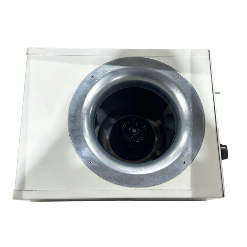
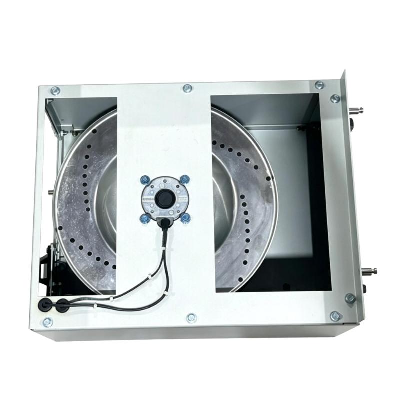
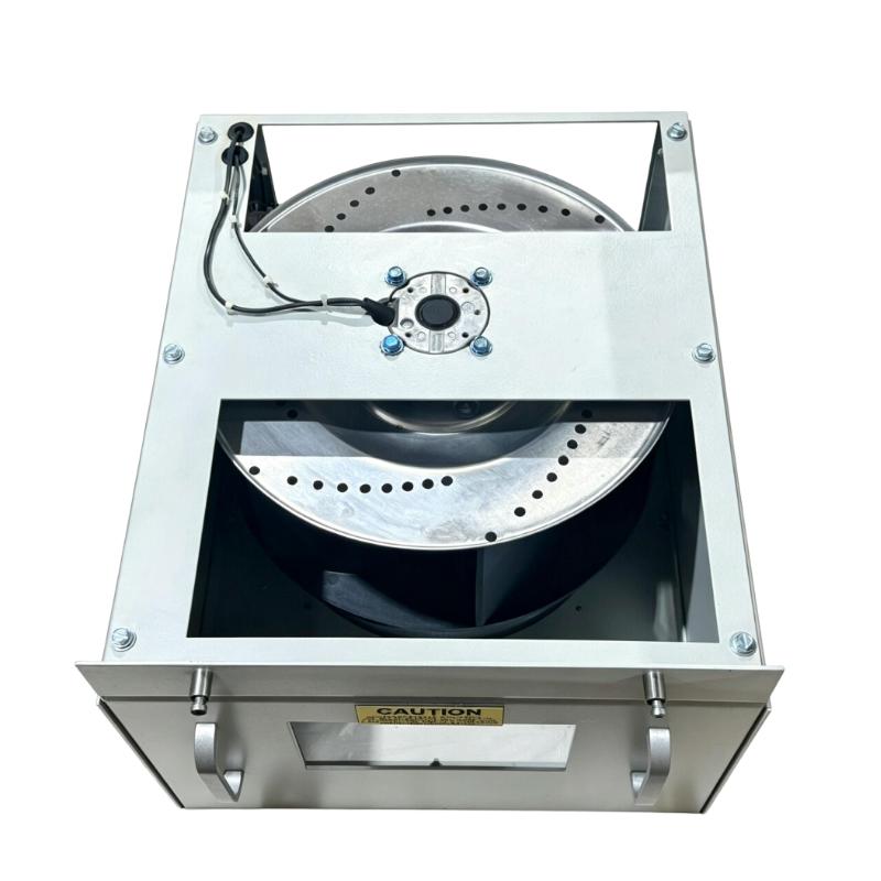
- GE
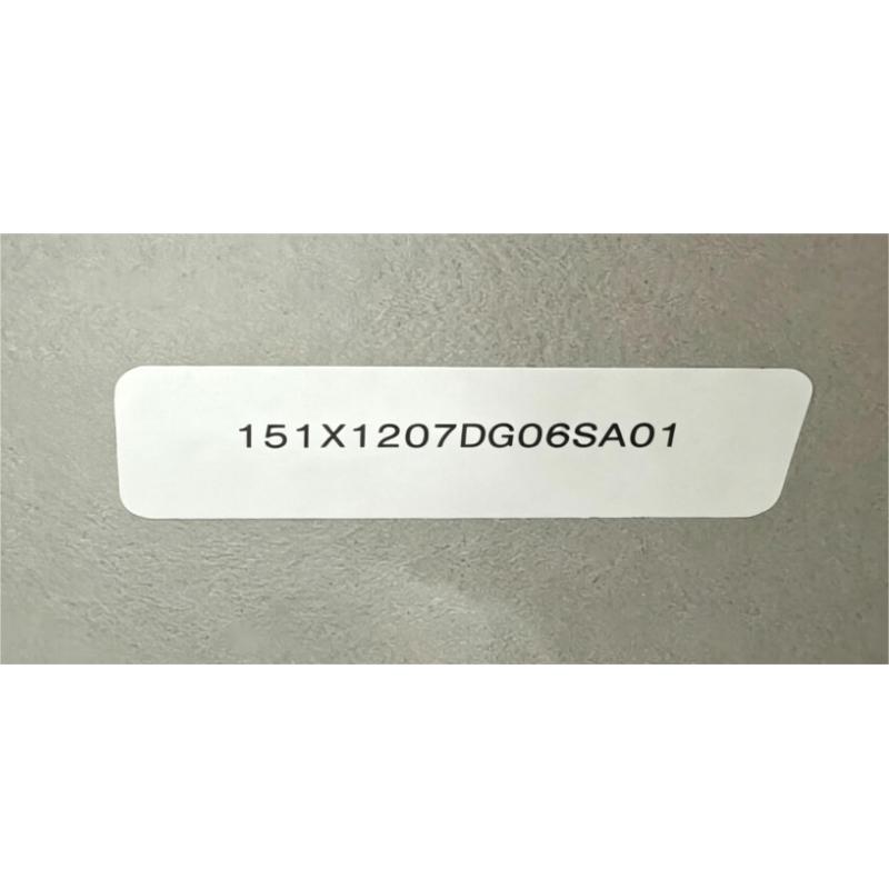
- 151X1207DG06SA01
- Blower Module Assembly
- USA
- 580 × 250 × 380 mm
- 6.8 kg
- Xiamen, China
- New & In Stock
- T/T, PayPal, Western Union
- 1 Year
- 1-3 Working Days
- DHL, UPS, TNT, FedEx and EMS.
- 24-Hour Service
- COO
- 5
Our advantage

Global Logistics
We have a 10-year logistics and express cooperation agreement, so our products can be shipped to any place in the world.

Brand new and original
Our products are imported in bulk from the place of origin. Because of the cooperative relationship, our products are all original and 100% new.

24-hour service
We provide 7*24 hours service to our customers. We will be there whenever you need us.

Price advantage
All our products are priced very favorably because we have our own warehouse and supply.
| Company Information | |||
| [email protected] | |||
| Mobile | +8615980777398 | ||
| +8615980777398 | |||
| 15980777398 |
Product Overview
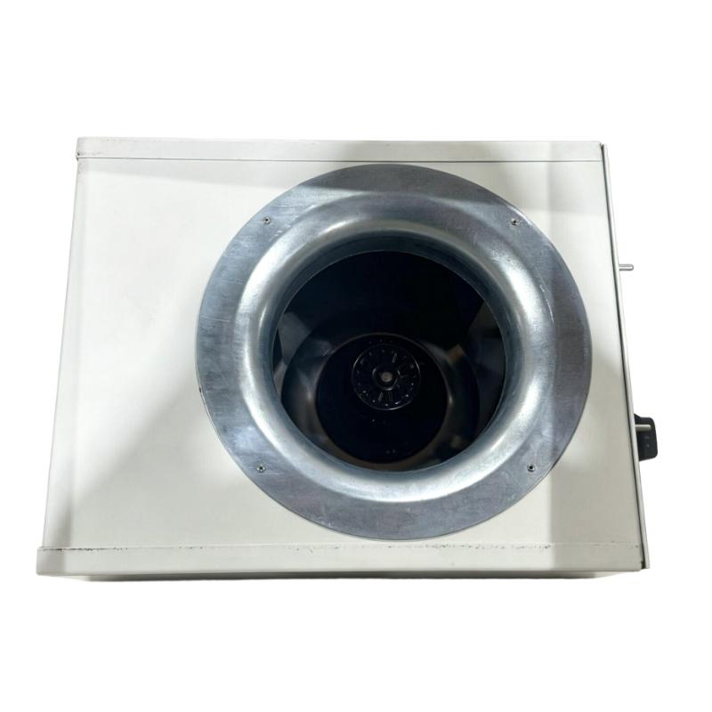
The GE 151X1207DG06SA01 is an EX2100 Blower Module Assembly used within the GE EX2100 excitation system to support airflow and thermal management for the associated electrical and power-control equipment. The blower assembly helps move cooling air through the designated equipment enclosure and across heat-producing components during operation.
In an excitation system, thermal conditions can directly affect the operating environment of power electronics and control hardware. The blower assembly therefore forms part of the equipment’s cooling infrastructure, maintaining the required airflow path while the EX2100 system is operating.
This type of assembly is particularly relevant during maintenance because blower performance can deteriorate through bearing wear, contamination, motor problems, restricted airflow, or electrical faults. Monitoring the condition of the blower assembly helps prevent a cooling problem from developing into an equipment-temperature issue.
Technical Specifications
| Parameter | Specification |
|---|---|
| Product Model | 151X1207DG06SA01 |
| Product Type | Blower Module Assembly |
| Series | EX2100 |
| Function | Cooling Airflow / Thermal Management |
| Dimensions | 580 × 250 × 380 mm |
| Weight | 6.8 kg |
Product Features
- EX2100 system application — Intended for the cooling infrastructure associated with GE EX2100 excitation equipment.
- Forced-air cooling — Generates airflow to assist thermal management within the equipment enclosure.
- Blower assembly construction — Combines the mechanical and airflow-related elements required for the blower function.
- Continuous operating support — Helps maintain airflow while excitation equipment is carrying an operating load.
- Maintenance-focused component — Blower condition can be inspected through airflow, noise, vibration, and operating-temperature observations.
- Cabinet cooling integration — Works as part of the broader thermal-management arrangement rather than as an independent control module.
Working Principle
The 151X1207DG06SA01 operates by mechanically generating forced airflow through the cooling path of the EX2100 equipment. When energized, the blower moves air through the designated enclosure or equipment passage, carrying heat away from components that generate thermal losses during operation.
The blower assembly itself does not regulate excitation output or execute control logic. Its function is physical thermal management: maintaining the airflow required by the equipment’s cooling arrangement.
During maintenance, blower performance can be assessed through operating noise, vibration, airflow, and the thermal condition of the associated equipment. A reduction in airflow can indicate mechanical wear, obstruction, motor problems, or another condition requiring investigation.
Role in a GE EX2100 Excitation System Cooling Architecture
| Architecture Layer | Role of 151X1207DG06SA01 |
|---|---|
| Excitation Power Equipment | Generates heat during normal electrical operation |
| Cooling Air Path | Provides the route through which heat is carried away |
| Blower Module Assembly | Produces forced airflow through the cooling system |
| Thermal Management | Helps maintain an acceptable operating environment for equipment |
| EX2100 System | Integrates cooling with excitation-system operation |
| Maintenance / Monitoring | Allows blower condition and airflow performance to be checked |
The blower assembly is therefore part of the thermal-management infrastructure supporting the EX2100 excitation system. It complements the electrical and control hardware by addressing the heat generated during operation.
Industrial Applications
| Application | Typical Use |
|---|---|
| Power Generation | Cooling infrastructure for generator excitation equipment |
| Gas Turbine Plants | Thermal management of excitation-system cabinets |
| Steam Turbine Generators | Supporting airflow through excitation equipment |
| Hydro Power Plants | Cooling support for generator excitation systems |
| Industrial Generators | Maintaining airflow around excitation-system components |
| Utility Excitation Systems | Forced-air cooling for electrical power-control equipment |
| EX2100 Maintenance Projects | Replacement of worn or defective blower assemblies |
Installation and Maintenance
- Verify the assembly model — Confirm that 151X1207DG06SA01 matches the existing EX2100 blower configuration before replacement.
- Isolate the equipment — Follow the plant’s approved shutdown, isolation, and electrical safety procedures before working on the blower assembly.
- Inspect the airflow path — Check for accumulated dust, foreign objects, blocked passages, or other restrictions.
- Check mechanical condition — Inspect the blower assembly for physical damage, loose hardware, or abnormal mechanical movement.
- Inspect electrical connections — Verify that the blower’s electrical connections are secure and free from visible damage.
- Check mounting security — Confirm that the assembly is properly secured and that mounting hardware has not loosened through vibration.
- Inspect rotating components — Check for abnormal wear, rubbing, excessive play, or other indications of mechanical deterioration.
- Verify airflow direction — Confirm that the blower moves air through the intended cooling path after installation.
- Perform a controlled operational test — After completing installation, verify that the blower starts and operates correctly under the applicable commissioning procedure.
- Monitor operating condition — Check abnormal noise, vibration, airflow reduction, or unusual temperature behavior during operation.
- Investigate cooling alarms promptly — If the excitation equipment reports an abnormal thermal condition, inspect the blower and airflow path as part of the initial investigation.
- Record maintenance activity — Document blower replacement, inspection results, observed conditions, and any related cooling-system work.
Related Components
| Component | Relationship |
|---|---|
| GE EX2100 Excitation System | Main system associated with the blower assembly |
| EX2100 Power Components | Generate heat that must be managed by the cooling system |
| Cooling Air Duct / Passage | Provides the airflow route through the equipment |
| Blower Electrical Connection | Supplies the blower assembly with operating power |
| Cabinet Ventilation Hardware | Works with the blower to maintain the intended airflow path |
| Temperature Monitoring Devices | Help identify abnormal thermal conditions within the equipment |
Recommended Related Models
| Model | Product Type | Application Relationship |
|---|---|---|
| GE 151X1207DG06SA01 | EX2100 Blower Module Assembly | Cooling assembly for EX2100 excitation equipment |
| GE EX2100 Control Modules | EX2100 Control Hardware | Provides control functions within the associated excitation system |
| GE EX2100 Power Modules | EX2100 Power Hardware | Handles excitation power functions and generates heat requiring thermal management |
| GE EX2100 Interface Modules | EX2100 Interface Hardware | Supports electrical and system-level connections within the excitation architecture |
| GE EX2100 Auxiliary Components | EX2100 Auxiliary Hardware | Supports the operating infrastructure of the excitation system |
Key Advantages
- Supports forced-air cooling within GE EX2100 excitation equipment.
- Helps maintain airflow around heat-generating electrical components.
- Forms part of the EX2100 thermal-management infrastructure.
- Provides a dedicated assembly for blower-related maintenance.
- Supports continuous excitation-system operation by maintaining the cooling path.
- Allows mechanical and airflow condition to be inspected independently from the excitation control functions.
Technical FAQs
What is the purpose of the GE 151X1207DG06SA01?
The 151X1207DG06SA01 is an EX2100 Blower Module Assembly used to support forced-air cooling within the associated excitation equipment. Its primary function is to maintain the airflow required for thermal management.
What symptoms can indicate a blower problem?
Typical indications can include reduced airflow, abnormal operating noise, excessive vibration, blower failure to start, or an increase in the temperature of the associated equipment. The actual cause should be determined by checking the blower, electrical supply, airflow path, and related cooling hardware.
Does the blower assembly control the excitation output?
No. The blower assembly provides cooling airflow and does not perform the excitation-control function. Excitation regulation and related control tasks are handled by the appropriate EX2100 electrical and control hardware.
What should be checked before replacing the blower?
First verify that the blower itself is the source of the problem. Check the electrical supply and connections, airflow path, mounting condition, mechanical movement, and signs of obstruction or contamination. If these checks indicate a blower assembly fault, replacement should follow the applicable EX2100 maintenance procedure.