

ProductPRODUCT
Featured products
Contact Us
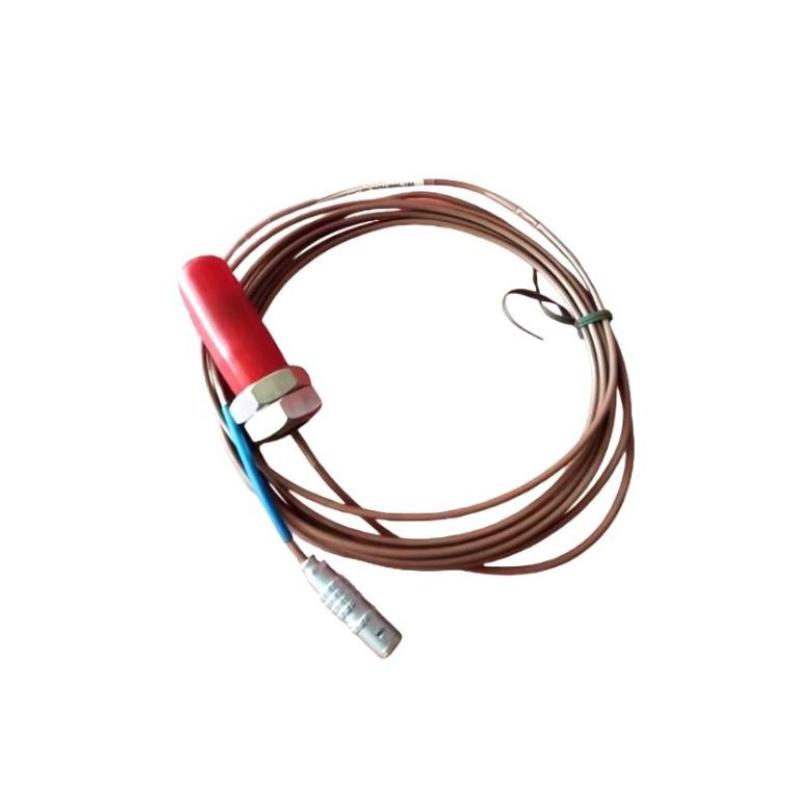
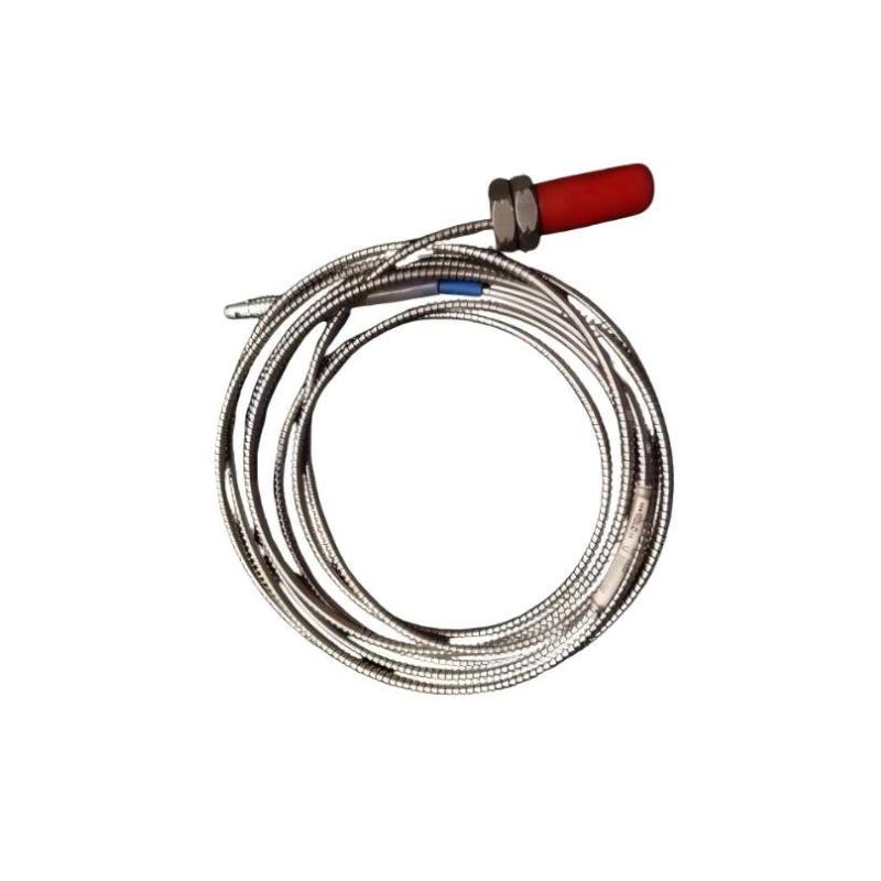
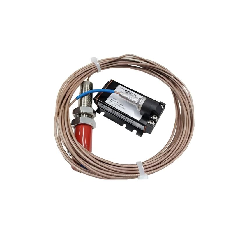
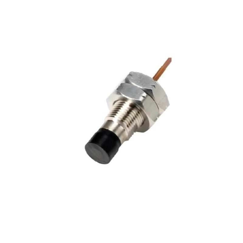
- Epro
- PR6424/004-101
- 16 mm Eddy Current Sensor
- Germany
- 16 mm
- 0.2 kg
- Xiamen, China
- New & In Stock
- T/T, PayPal, Western Union
- 1 Year
- 1-3 Working Days
- DHL, UPS, TNT, FedEx and EMS.
- 24-Hour Service
- COO
- 4
Our advantage

Global Logistics
We have a 10-year logistics and express cooperation agreement, so our products can be shipped to any place in the world.

Brand new and original
Our products are imported in bulk from the place of origin. Because of the cooperative relationship, our products are all original and 100% new.

24-hour service
We provide 7*24 hours service to our customers. We will be there whenever you need us.

Price advantage
All our products are priced very favorably because we have our own warehouse and supply.
| Company Information | |||
| [email protected] | |||
| Mobile | +8615980777398 | ||
| +8615980777398 | |||
| 15980777398 |
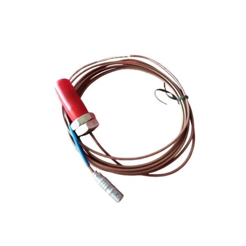
1. Product Overview
The Epro PR6424/004-101 16 mm Eddy Current Sensor is an industrial non-contact displacement sensor designed for monitoring critical rotating machinery. Belonging to the Epro PR6424 sensor family, it is intended for applications that require continuous measurement of shaft movement, relative displacement, vibration, position, and eccentricity.
Eddy current sensing technology enables the probe to measure the distance between its sensing tip and a suitable conductive metallic target without physical contact. This measurement principle is particularly useful in high-speed rotating equipment, where conventional contact-based measurement methods may introduce wear or interfere with normal machine operation.
The PR6424 series is widely associated with machinery condition monitoring applications involving steam turbines, gas turbines, hydro turbines, compressors, pumps, and fans. In these installations, shaft movement measurements can provide valuable information about operating conditions and mechanical behavior.
The 16 mm sensing head is designed for applications involving larger rotating shafts. When correctly installed and paired with compatible signal-conditioning electronics, the sensor can provide measurement signals for a machinery monitoring or protection system.
The PR6424/004-101 should be considered as part of a complete measurement arrangement rather than as an independent monitoring system. Depending on the configured system, the installation may include the sensor probe, connecting cable, signal converter, monitoring equipment, and control-system interfaces. These components must be matched to ensure correct signal conversion and reliable measurement.
For maintenance engineers, plant operators, and industrial automation suppliers, this sensor is relevant to applications where continuous shaft condition monitoring is important. Before selecting a replacement, users should verify the complete ordering code, cable arrangement, mounting thread, sensor length, converter compatibility, and required measurement range.
2. Technical Specifications
| Parameter | Specification |
|---|---|
| Brand | Epro |
| Product Model | PR6424/004-101 |
| Product Type | 16 mm Eddy Current Sensor |
| Sensor Technology | Non-contact eddy current measurement |
| Sensor Head Diameter | 16 mm |
| Primary Application | Shaft Displacement and Vibration Monitoring |
| Typical Measurement Targets | Suitable ferromagnetic metal shafts |
| Static Measurement Range | ±2.0 mm, based on documented PR6424 series specifications |
| Dynamic Measurement Range | Up to 1,000 μm, based on documented PR6424 series specifications |
| Typical Sensitivity | 4 V/mm (101.6 mV/mil) |
| Sensitivity Linearity | ±1.5% for the documented PR6424 specification |
| Nominal Center Air Gap | Approximately 2.7 mm |
| Frequency Range | 0–20 kHz for the documented PR6424 series |
| Typical Shaft Diameter | 80 mm or greater for the documented application |
| Sensor Body Thread | M18 × 1.5 for the applicable PR6424 configuration |
| Sensor Sleeve Material | Stainless steel |
| Cable Material | PTFE-insulated cable in the documented series |
| Signal Conditioning | Compatible Epro signal converter required for the applicable measurement system |
| Weight | Approximately 0.2 kg, as provided for this product listing |
| Dimensions | Verify the complete probe and cable configuration against the applicable mechanical drawing |
Specification note: The measurement characteristics above are based on published PR6424 family specifications. The exact sensor length, cable configuration, connector, temperature rating, and other suffix-specific characteristics of PR6424/004-101 should be verified against the corresponding ordering documentation. The 0.2 kg weight is the value supplied for this listing and may depend on the included cable configuration.
3. Function and Working Principle
The PR6424/004-101 operates using the eddy current principle. It measures the distance between the sensor tip and a conductive target by detecting changes in the electromagnetic interaction between the probe and the target surface.
This method allows the sensor to monitor shaft movement without direct mechanical contact.
3.1 Eddy Current Measurement
The sensor contains a coil that generates a high-frequency electromagnetic field when driven by compatible measurement electronics. When a conductive metallic target approaches the probe, eddy currents are induced in the target surface.
These currents change the electrical characteristics of the probe circuit. The associated measurement electronics evaluate this change and convert it into a signal related to the distance between the sensor tip and the target.
As the shaft moves relative to the probe, the measured gap changes. The measurement system can therefore detect movement in the direction of the sensor axis.
The sensor’s response depends on the target material, geometry, initial gap, mounting arrangement, and converter configuration. For reliable results, the target material and installation must be consistent with the applicable calibration requirements.
3.2 Shaft Displacement Measurement
Shaft displacement monitoring is used to observe the relative position of a rotating shaft and the machine structure. The PR6424 series is designed for this type of non-contact measurement.
In an appropriately configured installation, the sensor can measure static displacement within its specified linear range. This information may be used to identify changes in shaft position caused by mechanical loading, thermal movement, or other operating conditions.
The measurement result represents the relative distance between the probe and the target surface. It should not automatically be interpreted as absolute shaft position unless the overall installation and reference arrangement support that interpretation.
3.3 Shaft Vibration Monitoring
Rotating machinery can experience periodic shaft movement because of imbalance, misalignment, mechanical looseness, bearing-related problems, or other dynamic effects.
When the sensor is positioned correctly and connected to compatible electronics, changes in the sensor gap can be used to monitor dynamic shaft displacement.
The measurement system can provide information about vibration amplitude and changing shaft movement. The data may then be processed by machinery monitoring equipment to assess operating conditions or identify deviations from established baselines.
Actual monitoring performance depends on probe placement, the measurement electronics, installation quality, and the frequency characteristics of the complete system.
3.4 Position and Eccentricity Measurement
The PR6424 series can also support applications involving shaft position and eccentricity. Eccentricity refers to a deviation between the rotating shaft’s geometric center and its intended rotational center.
Changes in measured gap can help reveal relative movement or geometric variations during rotation. Such information may support equipment commissioning, condition monitoring, and maintenance investigations.
The suitability of a particular installation depends on the shaft geometry, target material, measurement direction, and required diagnostic method.
3.5 Signal Conversion
The probe itself is only one part of the measurement chain. A compatible signal converter provides the electrical excitation and processes the sensor response into a usable measurement output.
Depending on the selected system, the resulting signal may be connected to a machinery monitoring rack, a monitoring module, or other compatible measurement equipment.
The converter must match the sensor configuration, cable arrangement, and required output characteristics. Using an incompatible converter can lead to incorrect calibration, unreliable measurements, or failure to obtain a valid output.
4. Role in Industrial Machinery Monitoring Systems
Continuous monitoring of rotating machinery is important in industries where equipment availability, mechanical reliability, and operational stability directly affect production.
The PR6424/004-101 can form part of a machinery condition monitoring arrangement by providing non-contact shaft movement measurements.
4.1 Continuous Shaft Condition Monitoring
The sensor can measure shaft displacement at a selected monitoring location. When integrated with compatible monitoring electronics, this measurement can be used to track changes over time.
Establishing a baseline during normal operation allows maintenance personnel to compare later readings with historical conditions. Significant changes may justify additional inspection or diagnostic analysis.
The sensor does not independently determine the cause of a mechanical problem. Its measurements should be interpreted together with other monitoring data, operating conditions, and maintenance findings.
4.2 Machinery Protection Systems
Critical rotating machinery may use dedicated monitoring and protection equipment to evaluate shaft displacement, vibration, and related variables.
The PR6424 sensor can supply measurement information to a compatible system. That system may compare measurements with configured alarm or trip thresholds and initiate an appropriate response.
Protection functions depend on the complete monitoring architecture, including the sensor, converter, monitoring module, configured limits, and associated control interfaces. The probe alone does not provide a complete machinery protection function.
4.3 Predictive and Condition-Based Maintenance
Historical measurement trends can help maintenance teams identify changes in machinery behavior before a major failure occurs.
For example, a gradual change in shaft displacement may prompt a review of bearing condition, alignment, operating load, or other mechanical factors. Vibration trends can also help engineers determine when further diagnostics are required.
Condition-based maintenance decisions should be based on validated measurement data and appropriate engineering analysis rather than on a single sensor reading.
4.4 Integration with Plant Control Systems
Machinery monitoring systems may exchange status and measurement information with plant control systems. This allows operators to view relevant conditions alongside process variables such as load, speed, pressure, and temperature.
The PR6424 supplies the displacement-related measurement. The monitoring equipment and plant control architecture determine how that information is displayed, recorded, or used for alarms.
5. Industrial Applications
5.1 Steam Turbines
Steam turbines operate at high rotational speeds and require careful monitoring of shaft movement and vibration. Non-contact displacement sensors can provide measurements used to evaluate shaft behavior during startup, normal operation, and changing load conditions.
The PR6424 series is designed for critical turbomachinery applications and can be considered where its measurement characteristics and temperature rating match the installation.
Probe mounting, shaft material, cable routing, and converter compatibility must be confirmed before use.
5.2 Gas Turbines
Gas turbines contain rotating assemblies that operate under demanding mechanical and thermal conditions. Shaft displacement measurements can form part of a broader monitoring strategy intended to observe rotor behavior and detect abnormal changes.
The sensor must be installed at a suitable measurement point and paired with electronics designed for the specified probe configuration.
5.3 Hydro Turbines and Generators
Hydro turbines and associated generators require monitoring of rotating shafts, bearings, and mechanical alignment. Depending on the system design, eddy current sensors can measure relative shaft displacement and dynamic movement.
The resulting data can support condition trending and maintenance planning for equipment that operates continuously or serves critical power-generation duties.
5.4 Industrial Compressors
Centrifugal and other large compressors often require continuous shaft monitoring because changes in rotor dynamics can affect equipment performance and reliability.
A non-contact displacement sensor can provide measurement data for monitoring shaft movement. The complete system may combine this information with vibration, temperature, pressure, and speed measurements to support a more comprehensive assessment.
5.5 Pumps and Fans
Large industrial pumps and fans may operate under variable flow, load, and speed conditions. Shaft movement measurements can help engineers investigate abnormal vibration or changes in mechanical behavior.
The suitability of a 16 mm probe depends on the shaft dimensions, available mounting space, target material, and the measurement system’s configuration.
5.6 Power Generation and Process Industries
Power stations, petrochemical plants, and other process facilities frequently rely on critical rotating machinery. Unplanned equipment shutdowns can affect production and maintenance costs.
The PR6424/004-101 may be considered for compatible installations where non-contact shaft measurement is required. Engineers should verify the environmental and electrical requirements of the actual application before specifying the sensor.
6. Installation and System Integration
Correct installation is essential for achieving reliable measurements from an eddy current sensor. Probe positioning, target material, mounting stability, cable routing, and converter configuration all affect the measurement result.
6.1 Mechanical Mounting
The 16 mm sensor head is designed for installation near a suitable metallic target. The probe should be mounted securely so that its position remains stable during machine operation.
For the applicable PR6424 configuration, the documented sensor body thread is M18 × 1.5. Confirm the exact thread, body length, mounting hardware, and cable arrangement for PR6424/004-101 before preparing the installation.
The sensor must be positioned so that the target remains within the specified measurement range throughout normal operation. Adequate clearance should be provided to prevent contact between the probe and the rotating shaft.
The installation should also account for expected shaft movement, thermal expansion, maintenance access, and the possibility of mechanical changes during startup or shutdown.
6.2 Initial Gap Adjustment
Initial gap adjustment is a critical step in eddy current sensor installation. The distance between the probe tip and the target determines the operating point within the sensor’s measurement range.
The documented PR6424 family specification gives a nominal center air gap of approximately 2.7 mm. This value should be treated as a family reference rather than a substitute for the exact installation procedure.
Use the applicable converter instructions, sensor calibration information, and mechanical drawing to establish the correct gap. An unsuitable initial gap may reduce available measurement range or cause the system to operate outside its intended linear region.
6.3 Target Material and Surface Conditions
Eddy current sensors respond to the electrical properties of the target material. The PR6424 documentation identifies ferromagnetic steel, including 42CrMo4 as a standard reference material, for the specified performance characteristics.
Changes in target material, surface geometry, coating, or calibration conditions can influence measurement behavior.
Where accurate measurement is required, verify that the actual shaft material and surface conditions match the assumptions used for system calibration.
6.4 Cable Routing and Protection
The probe cable carries the sensor signal to the compatible measurement electronics. Cable length, connector type, shielding arrangement, and cable condition must match the selected system.
Route sensor cables away from high-current conductors and other sources of electrical interference where practical. Protect the cable against abrasion, excessive bending, hot surfaces, oil exposure, and mechanical damage.
Observe the minimum bending radius specified for the exact cable configuration. Do not assume that armored and unarmored versions have identical installation requirements.
6.5 Signal Converter Compatibility
A suitable signal converter is required for the applicable PR6424 measurement system. The converter provides the electrical interface and processes the probe response into a usable output.
Before installation, verify that the converter supports the exact probe configuration and cable arrangement. Check the output characteristics and ensure that the connected monitoring equipment accepts the signal.
A complete system compatibility review should include the probe, cable, converter, monitoring module, and any required accessories.
6.6 Commissioning and Verification
After mechanical and electrical installation, verify the sensor gap and the converter configuration before placing the machinery into service.
Commissioning should include:
- Confirming the correct sensor model and cable arrangement.
- Checking the mounting thread and mechanical stability.
- Verifying the target material and probe orientation.
- Setting the initial gap according to the applicable instructions.
- Checking the converter and monitoring-system configuration.
- Confirming that the output changes in the expected direction when the gap changes.
- Reviewing the measurement signal for noise, instability, or unexpected offsets.
Where the sensor is part of a protection system, the complete alarm and trip logic should be tested under an approved procedure. Do not rely solely on a valid sensor output as evidence that the entire protection system is functional.
7. Compatible System Components
The PR6424/004-101 is intended to operate as part of a compatible eddy current measurement system. The following components describe the typical arrangement.
| Component | Function |
|---|---|
| PR6424/004-101 Sensor Probe | Measures the gap between the sensor and a suitable conductive target |
| Compatible Extension or Connecting Cable | Connects the probe to the measurement electronics according to the configured system |
| Epro CON-Series Signal Converter | Excites the sensor and converts its response into a usable measurement output |
| Machinery Monitoring Module | Processes or monitors the sensor signal as part of a larger monitoring system |
| Shaft or Metallic Target | Provides the measurement surface |
| Mounting Bracket or Probe Holder | Maintains the required sensor position |
| Cable Protection Accessories | Help protect the connection against mechanical or environmental damage |
| Plant Monitoring System | Displays, records, or evaluates the measurement data |
Not every component listed is necessarily included with the sensor. The exact combination depends on the installed system and the selected probe configuration.
Before ordering, verify the required converter model, connector type, cable length, mounting accessories, and monitoring-system input characteristics.
8. Recommended Alternative Models
Selecting an alternative sensor requires matching the measurement diameter, operating environment, target geometry, cable configuration, sensitivity, and converter compatibility.
| Model | General Description | Selection Consideration |
|---|---|---|
| Epro PR6424/004-101 | 16 mm eddy current sensor | Original model reference; confirm the exact configuration |
| Epro PR6424 Series | 16 mm eddy current sensor family | Other variants may differ in probe length, cable, armor, connector, or ordering configuration |
| Epro PR6425 Series | 16 mm eddy current sensor for demanding temperature applications | Designed for different high-temperature requirements; verify the complete system compatibility |
| Epro PR6423 Series | 8 mm eddy current sensor family | Smaller sensing head and different measurement characteristics; not a direct substitute |
| Compatible Epro CON-Series Converter | Signal-conditioning component for supported probes | Must be matched to the probe and measurement-system configuration |
The models above are alternatives for evaluation, not guaranteed drop-in replacements. In particular, a different probe diameter or sensor family can change the measurement range, sensitivity, mounting requirements, and calibration.
When replacing a PR6424/004-101, use the original part number, installation drawing, cable details, and converter information to identify a suitable replacement. If the exact variant is unavailable, confirm the replacement configuration with the equipment documentation before installation.
9. Key Advantages of the Epro PR6424/004-101
Non-Contact Measurement
The eddy current principle enables shaft displacement measurement without direct contact between the sensor and the rotating target. This avoids mechanical contact at the sensing interface during normal operation.
Designed for Critical Rotating Machinery
The PR6424 family is intended for monitoring applications involving turbines, compressors, pumps, fans, and other large rotating machines.
16 mm Sensing Head
The 16 mm probe diameter is suitable for applications designed around this sensor family. The final mounting arrangement must still provide the necessary clearance and stable positioning.
Support for Static and Dynamic Measurements
The documented family specifications include a static measurement range of ±2.0 mm and dynamic measurement capability up to 1,000 μm. These characteristics support applications involving shaft position and dynamic displacement when the complete system is configured correctly.
Defined Sensitivity Characteristics
The documented PR6424 specifications provide a sensitivity of 4 V/mm and a linearity figure of ±1.5%. These values help engineers evaluate the sensor for suitable measurement applications.
Integration with Compatible Monitoring Electronics
The sensor can be integrated into an appropriate measurement chain using compatible signal-conditioning and monitoring equipment.
Useful for Condition-Based Maintenance
Continuous displacement measurements can help maintenance personnel establish operating baselines, monitor changes, and identify when further machinery investigation may be necessary.
10. Technical FAQs
Q1: What is the Epro PR6424/004-101 used for?
It is a 16 mm non-contact eddy current sensor intended for displacement measurement and machinery condition monitoring. Typical applications include shaft vibration, relative displacement, position, and eccentricity monitoring.
Q2: What is the sensor head diameter?
The sensor head diameter is 16 mm.
Q3: How does an eddy current sensor measure shaft movement?
The probe generates an electromagnetic field. A conductive target changes the electrical characteristics of the sensing coil, and compatible measurement electronics convert that change into a signal related to the gap between the probe and target.
Q4: What is the measurement range of the PR6424 series?
Published PR6424 family specifications give a static range of ±2.0 mm and dynamic measurement capability up to 1,000 μm. The applicable operating range must be verified against the exact sensor and converter configuration.
Q5: What is the typical sensitivity?
The documented PR6424 family specification gives a sensitivity of 4 V/mm, equivalent to approximately 101.6 mV/mil, with a linearity figure of ±1.5%. Confirm the relevant calibration and output details for the complete measurement system.
Q6: Does the sensor require a signal converter?
The applicable PR6424 measurement arrangement requires compatible measurement electronics or a signal converter to provide excitation and process the sensor response. The exact converter depends on the probe configuration and output requirements.
Q7: What material can the sensor measure?
The documented PR6424 performance specifications reference ferromagnetic steel, including 42CrMo4 as a standard target material. Target material and geometry should be verified because they affect measurement characteristics.
Q8: What is the weight of PR6424/004-101?
The weight supplied for this product listing is approximately 0.2 kg. The actual weight can depend on the probe and cable configuration.
Q9: Can the PR6424/004-101 be used to monitor turbine shaft vibration?
The PR6424 family is designed for critical rotating machinery monitoring, including turbine applications. Suitability depends on the exact sensor configuration, mounting arrangement, target characteristics, converter, and monitoring system.
Q10: What should be checked if the measurement signal is unstable?
Inspect the probe mounting, initial gap, cable condition, connector integrity, target surface, grounding and shielding arrangement, converter compatibility, and monitoring-system configuration. Compare the signal with established operating data before determining whether the issue is mechanical or electrical.
11. Conclusion
The Epro PR6424/004-101 16 mm Eddy Current Sensor is intended for non-contact displacement measurement in industrial machinery monitoring applications. Based on the PR6424 family design, it can support shaft displacement, vibration, position, and eccentricity monitoring when paired with compatible signal-conditioning electronics.
Its non-contact operating principle makes it suitable for applications involving rotating equipment where continuous shaft movement measurements are required. Proper sensor selection, target compatibility, initial gap adjustment, cable installation, and converter configuration are essential to reliable operation.
For industrial maintenance teams and automation suppliers, the PR6424/004-101 is a relevant product reference for existing Epro machinery monitoring installations. Before purchase or replacement, verify the exact suffix-specific specifications and confirm that the probe, cable, converter, and monitoring equipment form a compatible measurement system.