

ProductPRODUCT
Featured products
Contact Us
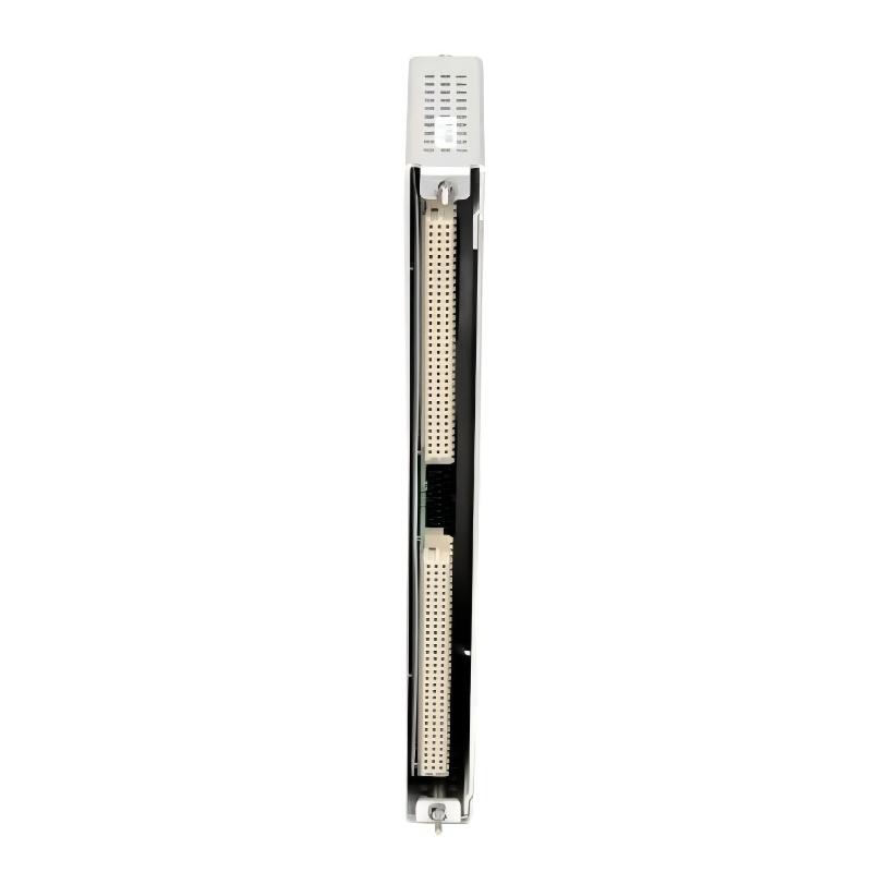
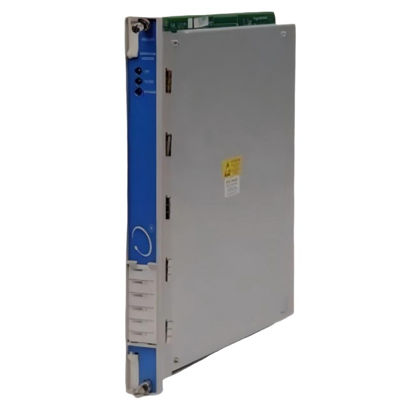
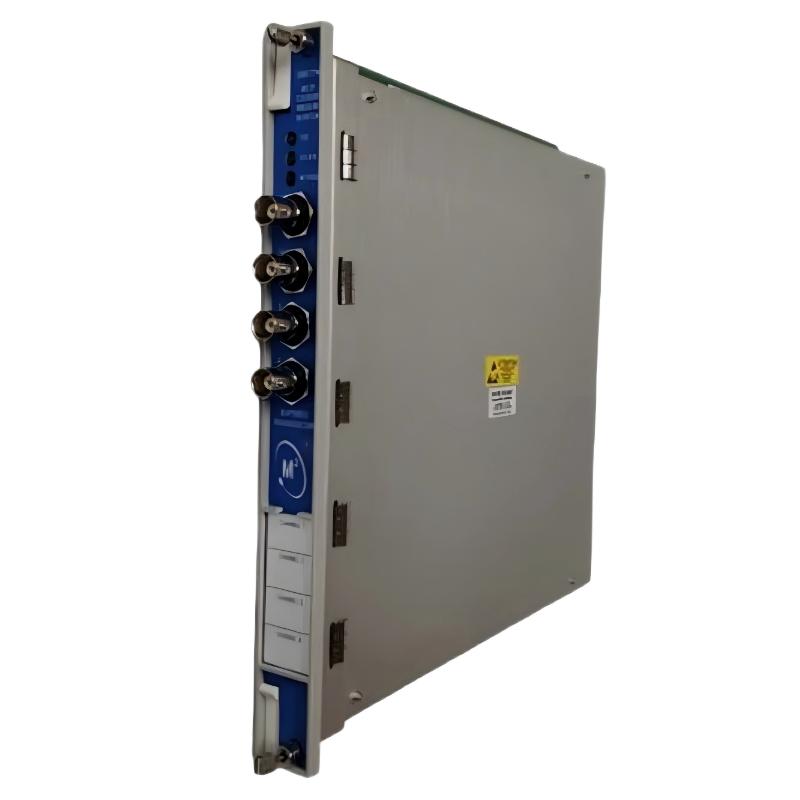
- Bently Nevada
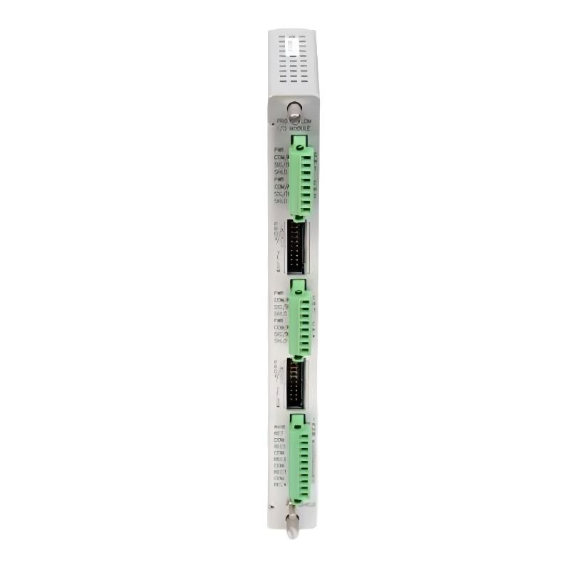
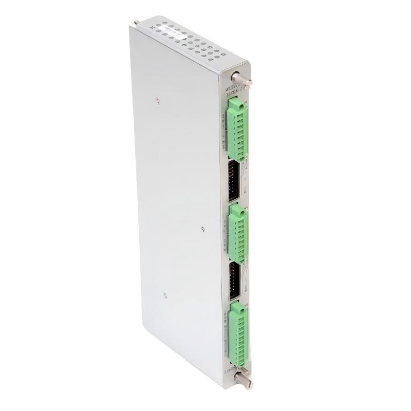
- 3500/77M-04-00 143737-01
- 4-channel Machinery Protection and Diagnostic Module
- USA
- 241.3 × 24.4 × 241.8 mm
- 0.91kg
- Xiamen, China
- New & In Stock
- T/T, PayPal, Western Union
- 1 Year
- 1-3 Working Days
- DHL, UPS, TNT, FedEx and EMS.
- 24-Hour Service
- COO
- 1
Our advantage

Global Logistics
We have a 10-year logistics and express cooperation agreement, so our products can be shipped to any place in the world.

Brand new and original
Our products are imported in bulk from the place of origin. Because of the cooperative relationship, our products are all original and 100% new.

24-hour service
We provide 7*24 hours service to our customers. We will be there whenever you need us.

Price advantage
All our products are priced very favorably because we have our own warehouse and supply.
| Company Information | |||
| [email protected] | |||
| Mobile | +8615980777398 | ||
| +8615980777398 | |||
| 15980777398 |
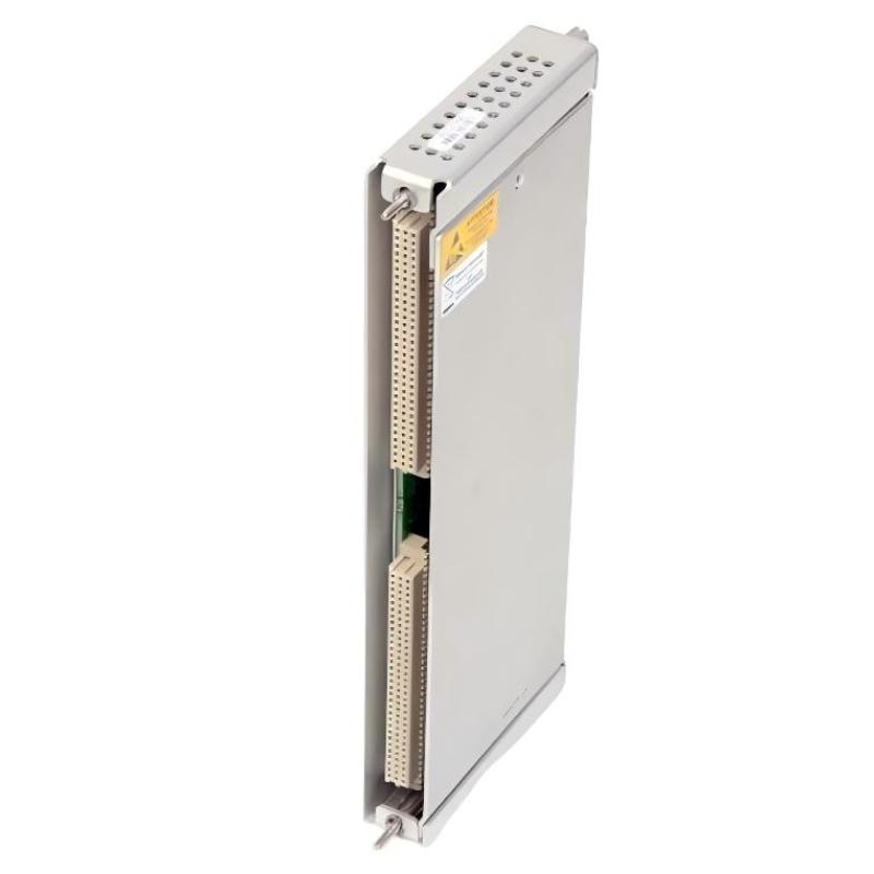
Bently Nevada 3500/77M-04-00 (143737-01) — Technical Specifications, Product Description, Industrial Applications, Advantages, and Recommended Models
1. Product Overview
The Bently Nevada 3500/77M-04-00 is a configuration of the 3500 series reciprocating cylinder pressure monitoring system. It is designed to monitor pressure-related operating conditions in reciprocating compressors and provide information that can be used to assess equipment performance, identify abnormal operating conditions, and support machinery protection.
The associated part number 143737-01 identifies the cylinder-pressure input/output (I/O) module with external terminations. This distinction is important when purchasing or replacing equipment: 3500/77M-04-00 is the monitor configuration, while 143737-01 is the associated external-termination I/O module. They are related parts of the monitoring arrangement, not two interchangeable designations for the same physical component.
The external-termination configuration is intended for installations in which the field wiring connects through a separately mounted termination block. This arrangement can be useful when field cables need to be organized away from the rack or when maintenance personnel require convenient access to the wiring connections.
The 3500/77M monitors pressure signals from compatible transducers and processes them into measurements relevant to reciprocating compressor operation. These include suction pressure, discharge pressure, maximum and minimum pressure, compression ratio, and calculated rod-loading variables.
For industrial users, the main value of this equipment is that it provides information about compressor cylinder behavior that cannot necessarily be obtained from shaft vibration or general process-pressure measurements alone.
2. Brand, Series, and Product Identification
| Parameter | Technical information |
|---|---|
| Brand | Bently Nevada |
| Product series | 3500 Machinery Protection System |
| Product family | Reciprocating Machinery Monitoring |
| Main monitor model | 3500/77M-04-00 |
| Associated I/O module | 143737-01 |
| Product name | Reciprocating Cylinder Pressure Monitor and External-Termination I/O Module |
| Primary function | Dynamic cylinder-pressure monitoring |
| Main application | Reciprocating compressor monitoring and protection |
| Measurement inputs | Compatible pressure-transducer signals |
| Maximum monitor channel capacity | Four pressure channels |
| Termination arrangement | External field termination |
| Installation platform | Compatible 3500 rack system |
| Measurement processing | Pressure-signal conditioning and calculated operating variables |
| Alarm capability | Configurable Alert and Danger setpoints, subject to the selected configuration |
| Typical installation | Industrial compressor monitoring and machinery protection |
| Standalone operation | Not intended to replace the complete compatible monitoring system |
| Physical configuration | Monitor module, rear I/O module, termination accessories, and associated wiring |
2.1 Understanding the Model Number
The ordering designation 3500/77M-04-00 identifies a particular configuration of the 3500/77M monitor.
| Model designation | Meaning |
|---|---|
| 3500 | Machinery protection system series |
| 77M | Reciprocating cylinder pressure monitor |
| 04 | External-termination I/O configuration |
| 00 | No additional agency-approval option selected in this ordering configuration |
| 143737-01 | Associated cylinder-pressure I/O module with external terminations |
The final two digits of an ordering designation should not be ignored. Different configuration codes can affect the I/O arrangement and applicable approvals.
For replacement work, the full monitor designation and the I/O module part number should be checked separately against the existing installation.
3. Detailed Technical Specifications
The following tables distinguish the monitor’s operating specifications from the physical details of the associated external-termination I/O module.
3.1 Monitor Performance Parameters
| Parameter | Specification | Description |
|---|---|---|
| Model | 3500/77M-04-00 | Four-channel reciprocating cylinder pressure monitoring configuration |
| Associated I/O part number | 143737-01 | External-termination cylinder-pressure I/O module |
| Measurement principle | Pressure-transducer signal conditioning | Converts compatible sensor signals into useful pressure measurements |
| Number of input channels | Up to 4 | Supports multiple selected cylinder-pressure measurement points |
| Input type | Approved positive-voltage pressure transducers | Sensor compatibility must be verified |
| Input impedance | 50 kΩ | Electrical input characteristic |
| Frequency response | 0–5.5 kHz | Supports dynamic pressure signal monitoring |
| Nominal transducer supply | +23.0 V DC | Power supplied to compatible transducers |
| Transducer supply tolerance | ±0.8 V DC | Specified variation around nominal supply |
| Transducer current limiting | 24.5 mA per channel | Current limit for the sensor supply |
| Maximum stated monitor power consumption | Approximately 7.8 W | At full transducer-supply load |
| Pressure accuracy at 25°C | ±0.5% of full scale | Under the specified operating conditions |
| Pressure accuracy over the operating temperature range | ±1.0% of full scale | Subject to specified environmental and signal conditions |
| Monitor operating temperature | -30°C to +65°C | Operating environmental range |
| Monitor storage temperature | -40°C to +85°C | Storage environmental range |
| Maximum number of Alert setpoints | One for each active measured variable | Depends on the configured variables |
| Danger setpoints | Up to two active measured variables | Depends on the selected monitor configuration |
| Front-panel status indication | OK, TX/RX, Bypass | Indicates module health, communication activity, and bypass status |
| Signal diagnostics | Buffered transducer outputs | Supports examination of compatible input signals |
| Rack requirement | Compatible 3500 rack | Requires the correct system hardware |
| Timing requirements | Configuration-dependent | Appropriate crank-angle or multi-event timing information may be required |
3.2 Pressure Measurement Variables
The monitor can calculate eight measurement variables associated with reciprocating compressor operation.
| Measurement variable | Technical meaning | Practical use |
|---|---|---|
| Suction pressure | Pressure during the cylinder intake portion of the cycle | Helps evaluate intake conditions and possible suction-side abnormalities |
| Discharge pressure | Pressure associated with the discharge portion of the cycle | Helps assess discharge conditions and compression performance |
| Maximum pressure | Highest pressure detected within the configured measurement cycle | Supports assessment of peak cylinder loading |
| Minimum pressure | Lowest pressure detected within the configured measurement cycle | Helps identify unusual low-pressure behavior |
| Compression ratio | Calculated relationship between relevant discharge and suction pressures | Supports assessment of compression performance |
| Peak rod compression | Calculated peak compressive rod loading | Helps assess mechanical loading |
| Peak rod tension | Calculated peak tensile rod loading | Helps identify loading conditions that may require investigation |
| Degree of rod reversal | Calculated parameter associated with the rod-loading cycle | Supports evaluation of rod-load reversal behavior |
The five pressure-related variables are associated with a single monitored chamber. The three rod-loading variables are calculated using the relevant channel measurements and configured mechanical parameters.
These variables should be interpreted in the context of the compressor design, operating speed, gas properties, and measurement configuration. A pressure trend alone does not establish the cause of a mechanical problem.
3.3 Pressure Range and Signal Scaling
The configured measurement range must match the characteristics of the installed pressure transducer.
| Nominal pressure full-scale range | Nominal scaling factor |
|---|---|
| 100 psia | 95,000 mV/psi |
| 250 psia | 38,000 mV/psi |
| 500 psia | 19,000 mV/psi |
| 1,000 psia | 9,500 mV/psi |
| 2,500 psia | 3,800 mV/psi |
| 5,000 psia | 1,900 mV/psi |
| 10,000 psia | 950 mV/psi |
These are pressure-monitor family scaling values, not a declaration that every transducer range is suitable for every installation.
The pressure range, transducer calibration, wiring, and software configuration must all be consistent. An incorrect scaling factor can cause misleading measurements and inappropriate alarm behavior even if the monitor hardware is functioning correctly.
4. Dimensions and Weight
Physical specifications need to be separated by component because the 3500/77M monitor and the 143737-01 I/O module have different functions and physical arrangements.
| Component | Model or part number | Dimensions (H × W × D) | Weight (kg) | Notes |
|---|---|---|---|---|
| Cylinder pressure monitor | 3500/77M | 241.3 × 24.4 × 241.8 mm | 0.91 | Monitor module only |
| External-termination I/O module | 143737-01 | Approximately 160 × 160 × 120 mm | Approximately 0.8 | Preliminary catalog-listed values; confirm against the exact hardware revision |
| External termination block | 125808-10 | Not confirmed | Not confirmed | External termination arrangement with Euro-style connectors |
| External termination block | 128015-10 | Not confirmed | Not confirmed | External termination arrangement with terminal-strip connectors |
| Complete installed assembly | 3500/77M-04-00 + 143737-01 | Depends on the complete installation | Not confirmed | Excludes or includes separate accessories according to the installed configuration |
The monitor’s dimensions and 0.91 kg weight refer to the monitor module itself. The I/O module’s approximate dimensions and weight should be treated as preliminary identification data rather than guaranteed engineering limits.
For a formal equipment specification, transport calculation, or procurement contract, obtain the physical drawing and weight for the exact part number and revision. Do not use the monitor’s dimensions as the dimensions of the external-termination I/O module.
5. Product Introduction and Operating Principle
5.1 Purpose of the 3500/77M
Reciprocating compressors operate through repeated suction and compression cycles. Cylinder pressure changes continuously throughout each cycle, and those changes are influenced by the compressor’s mechanical condition, process conditions, valve performance, and operating load.
The 3500/77M is designed to monitor these dynamic pressure signals. It processes input signals from compatible pressure transducers and calculates measurements that help engineers assess compressor performance and identify deviations from established operating patterns.
The system is intended for continuous machinery monitoring rather than occasional manual pressure checks. Continuous monitoring makes it possible to observe how measurements change as the compressor operates under different loads and process conditions.
5.2 How the Monitoring Process Works
A typical installation follows this sequence:
1. Pressure measurement
Compatible pressure transducers measure cylinder pressure.
2. External termination
Field signals pass through the specified termination block and interconnect wiring.
3. Signal conditioning
The monitor processes the incoming pressure signals.
4. Measurement calculation
Pressure values and calculated compressor operating variables are produced.
5. Alarm evaluation and maintenance assessment
Configured alarm limits and trends help identify conditions that require attention.
This process provides operators with more than a simple pressure reading. It allows them to evaluate the relationship between pressure behavior, configured limits, and other information available from the machinery monitoring system.
5.3 Role of the External-Termination I/O Module
The 143737-01 is intended for external termination of compatible cylinder-pressure transducer wiring.
In this arrangement, the field wiring is connected at an external termination block instead of terminating directly at the rear I/O module inside the rack. The signals are carried through the specified interconnect arrangement to the monitoring system.
This arrangement can be useful when the installation requires a separate field-wiring location, organized cable routing, or convenient access during inspection and maintenance.
The external-termination version should not be confused with part number 143729-01, which is the corresponding cylinder-pressure I/O module with internal terminations.
5.4 Alarm and Protection Functions
The monitor compares configured measured variables with user-defined alarm limits.
An Alert setting can indicate that a measured variable has moved outside its normal operating range. A Danger setting can identify a more serious condition for the selected variables and configured protection logic.
The actual response depends on the complete system design, including alarm configuration, relay or control interfaces, bypass handling, and the site’s operating procedures.
For critical machinery, alarm thresholds should be established using the compressor manufacturer’s limits, engineering calculations, commissioning data, and applicable protection requirements.
6. Main Industrial Applications
6.1 Oil and Gas Production
Reciprocating compressors are used in gas gathering, gas boosting, reinjection, and other pressure-management duties throughout oil and gas facilities.
The 3500/77M can monitor cylinder-pressure behavior and calculate pressure-related variables that help maintenance personnel identify changes in operating conditions.
Typical applications include:
-
Natural gas gathering and compression stations.
-
Gas reinjection systems.
-
Reciprocating compressor packages.
-
Gas processing and transmission facilities.
-
Industrial gas boosting installations.
In these applications, cylinder-pressure monitoring can complement vibration monitoring and process instrumentation, helping engineers obtain a more complete picture of the compressor’s operating condition.
6.2 Petrochemical and Chemical Processing
Chemical and petrochemical facilities may operate reciprocating compressors under changing gas composition, pressure, and load conditions.
Pressure measurements can help engineers investigate changes in compression performance, abnormal pressure patterns, and operating conditions that may require additional inspection.
The monitor may be suitable for compatible process-gas compressor installations where cylinder-pressure measurements are part of the machinery monitoring strategy.
6.3 Refining Facilities
Refineries rely on compressors to support a range of gas-handling and process operations.
The 3500/77M can provide information about cylinder suction pressure, discharge pressure, compression ratio, and calculated rod loading. When interpreted alongside process measurements and vibration data, these variables can support investigations into changes in compressor performance.
6.4 Fertilizer and Ammonia Production
High-pressure reciprocating compressors are used in some fertilizer and ammonia production processes.
In such applications, monitoring pressure behavior and calculated mechanical loads can help operators assess whether the compressor is operating within its intended limits.
The pressure transducers, accessories, and complete installation must be suitable for the actual process pressure, temperature, gas properties, and applicable safety requirements.
6.5 Hydrogen and Industrial Gas Compression
Hydrogen and other industrial gases may require specialized compressor arrangements and operating limits.
Cylinder-pressure monitoring can provide information about the compression cycle and help engineers identify deviations from expected pressure behavior. It can also support the investigation of load-related changes when combined with appropriate mechanical and process measurements.
Suitability must be assessed against the actual compressor design and approved transducer arrangement rather than assumed from the monitor’s pressure range alone.
6.6 Power Generation and Utility Facilities
Some power-generation facilities use reciprocating compressors in fuel-gas systems and auxiliary services.
The monitor can contribute cylinder-pressure data to the facility’s machinery condition monitoring program. It is particularly relevant where compressor performance and mechanical loading require continuous assessment.
6.7 Industrial Compressor Maintenance
The 3500/77M is also relevant to maintenance teams that need to compare current operating behavior with a known baseline.
After an overhaul, valve replacement, adjustment, or other maintenance activity, pressure measurements can help engineers evaluate whether the machine’s behavior has changed as expected.
The monitor does not independently determine the root cause of every abnormal reading. Its data is most useful when combined with maintenance history, sensor checks, operating conditions, and engineering analysis.
7. Product Advantages
7.1 Dedicated Monitoring for Reciprocating Compressors
The principal advantage of the 3500/77M is its focus on cylinder-pressure behavior.
General vibration monitoring is valuable for identifying many mechanical problems, but it does not directly measure the pressure cycle inside a compressor cylinder. Pressure monitoring adds information about compression performance and loading that may not be apparent from vibration data alone.
7.2 Four-Channel Measurement Capability
The monitor supports up to four compatible pressure-input channels.
This makes it possible to monitor multiple selected measurement points through one monitor module, subject to the installed sensor arrangement and configuration.
For compressor packages with several cylinders or chambers, multi-channel monitoring can help maintenance teams compare operating behavior between selected measurement locations.
7.3 High-Frequency Pressure Signal Response
The specified 0–5.5 kHz frequency response supports the monitoring of dynamic pressure changes.
This is important because reciprocating compressors generate cyclic signals, and the waveform’s shape and timing can provide useful information beyond average pressure values.
Correct sensor selection and installation remain essential to obtaining meaningful measurements.
7.4 Multiple Calculated Variables
The monitor can provide pressure-related variables as well as calculated rod-loading information.
This supports a broader assessment of compressor operation than a single process-pressure measurement would provide.
Engineers can compare these variables against operating limits, historical baselines, and other machinery measurements to decide whether additional investigation is needed.
7.5 Configurable Alarm Limits
User-configurable Alert and Danger settings allow the monitoring system to be adapted to the intended application.
Properly selected alarm limits can help distinguish normal operating variation from conditions requiring attention.
The quality of the protection strategy depends on correct configuration, engineering validation, and regular review. Alarm settings should not be copied from another compressor without checking the equipment’s design and operating requirements.
7.6 External-Termination Wiring Arrangement
The 143737-01 provides an external-termination option for compatible pressure-transducer signals.
Separating field wiring from the rack can help organize cables and provide a convenient location for field connections. This can be particularly useful in installations where the rack and compressor are located in different areas.
The termination block, interconnect cable, and wiring arrangement must match the specified hardware.
7.7 Diagnostic Support
Status indicators and buffered signal outputs help qualified personnel examine the module’s condition and input signals.
These facilities can support troubleshooting when an unexpected pressure reading occurs. They may help identify wiring issues, transducer problems, or signal abnormalities before more extensive mechanical investigation is undertaken.
7.8 Integration With a Machinery Protection System
The monitor belongs to the 3500 machinery protection platform.
For an existing installation, using compatible modules within the same platform can help maintain a consistent monitoring architecture and simplify system-level integration.
Compatibility still needs to be confirmed at the hardware, firmware, I/O, and configuration levels. A module from the same series is not automatically a direct replacement for another module.
7.9 Support for Condition-Based Maintenance
Pressure trends and calculated operating variables can help maintenance personnel identify changes that develop over time.
When combined with vibration, temperature, process data, and maintenance records, these measurements can support condition-based maintenance planning and more focused equipment inspections.
The benefits depend on measurement quality, alarm management, maintenance practices, and the operating environment.
8. Five Same-Series or Closely Related Models
The following five models are relevant to reciprocating machinery monitoring or closely related measurement functions.
They are recommendations for comparison, not direct substitutes for the 3500/77M. Their functions differ, and the correct choice depends on the measurements required by the compressor.
| Model | Product type | Main technical parameters | Dimensions (H × W × D) | Weight (kg) |
|---|---|---|---|---|
| 3500/72M | Reciprocating rod-position monitor | Monitors compatible rod-position signals and related reciprocating-machine variables; configuration-dependent channels | Exact revision-specific dimensions to be confirmed | Exact part-number weight to be confirmed |
| 3500/70M | Reciprocating impulse-velocity monitor | Monitors impulse-velocity signals associated with reciprocating machinery | Exact revision-specific dimensions to be confirmed | Exact part-number weight to be confirmed |
| 3500/64M | Dynamic pressure monitor | Monitors compatible dynamic-pressure signals for machinery applications | Exact revision-specific dimensions to be confirmed | Exact part-number weight to be confirmed |
| 3500/42M | Proximitor/seismic monitor | Supports compatible proximity and seismic inputs for vibration and position monitoring | Exact revision-specific dimensions to be confirmed | Exact part-number weight to be confirmed |
| 3500/40M | Proximitor monitor | Processes compatible proximity-probe signals for machinery monitoring | Exact revision-specific dimensions to be confirmed | Exact part-number weight to be confirmed |
8.1 3500/72M — Reciprocating Rod-Position Monitor
The 3500/72M is one of the most relevant complementary models for reciprocating compressor applications.
It focuses on rod-position monitoring rather than cylinder pressure. Rod-position information can help engineers assess piston-rod movement and investigate abnormal movement patterns.
When used alongside cylinder-pressure measurements, rod-position data can provide another perspective on the machine’s mechanical condition.
Recommended application: reciprocating compressors that require rod-position monitoring in addition to pressure monitoring.
8.2 3500/70M — Reciprocating Impulse-Velocity Monitor
The 3500/70M is designed for monitoring impulse-velocity signals associated with reciprocating machinery.
This provides a different measurement perspective from cylinder-pressure monitoring. It may be useful where machine-impact or impulse-related behavior is an important part of the monitoring strategy.
The appropriate sensor and measurement arrangement must be selected for the specific machine.
Recommended application: installations requiring compatible impulse-velocity measurements to complement pressure and rod-position data.
8.3 3500/64M — Dynamic Pressure Monitor
The 3500/64M is associated with dynamic-pressure monitoring.
Although both the 3500/64M and 3500/77M relate to pressure measurements, they serve different monitoring applications and should not be treated as interchangeable. The 3500/77M is specifically designed for reciprocating cylinder-pressure monitoring and associated compressor variables.
Recommended application: systems requiring the particular dynamic-pressure measurement function supported by the 3500/64M.
8.4 3500/42M — Proximitor/Seismic Monitor
The 3500/42M is intended for compatible proximity and seismic measurement applications.
It can be relevant when a compressor installation also requires shaft-motion or vibration monitoring. These measurements can complement cylinder-pressure data by providing information about the machine’s mechanical response.
Recommended application: machinery installations requiring compatible proximity or seismic measurements.
8.5 3500/40M — Proximitor Monitor
The 3500/40M focuses on compatible proximity-probe signals.
Proximity measurements are used in machinery monitoring to assess relative shaft vibration and position in suitable installations. This is a different measurement function from the pressure measurements produced by the 3500/77M.
Recommended application: installations where proximity-probe measurements are required as part of the overall machinery protection system.
8.6 Comparison of the Five Related Models
| Model | Primary function | Relationship to the 3500/77M | Selection priority |
|---|---|---|---|
| 3500/72M | Rod-position monitoring | Closely related to reciprocating compressor condition monitoring | High when rod movement is a concern |
| 3500/70M | Impulse-velocity monitoring | Complementary reciprocating-machine measurement | Consider when impulse behavior must be monitored |
| 3500/64M | Dynamic-pressure monitoring | Related pressure-monitoring family, but different function | Consider when its specific pressure-monitoring function is required |
| 3500/42M | Proximity/seismic monitoring | Complementary mechanical-condition monitoring | High when vibration and shaft motion are important |
| 3500/40M | Proximity monitoring | Complementary shaft-motion measurement | Consider when proximity-probe monitoring is required |
The most relevant companion model depends on the condition being investigated. For reciprocating rod movement, the 3500/72M is a logical candidate. For vibration and shaft-motion monitoring, the 3500/42M or 3500/40M may be more appropriate.
9. Five Popular Models From the Same Brand
The following models cover common machinery protection, temperature measurement, speed monitoring, and system communication functions. They are suitable for consideration when expanding an existing monitoring installation or building a more complete equipment monitoring arrangement.
The dimensions and weights below are intentionally not assigned unsupported numerical values. Different revisions and ordering configurations can have different physical specifications, and the exact part number should be checked before ordering.
| Model | Product name | Main technical parameters | Dimensions (H × W × D) | Weight (kg) |
|---|---|---|---|---|
| 3500/25 | Enhanced Keyphasor Module | Processes compatible keyphasor signals for rotational reference and timing applications | Confirm exact part number and revision | Confirm exact part number |
| 3500/32 | Four-Channel Relay Module | Four relay channels; configured alarm and control outputs | Confirm exact part number and revision | Confirm exact part number |
| 3500/50M | Tachometer Module | Rotational-speed monitoring using compatible input signals | Confirm exact part number and revision | Confirm exact part number |
| 3500/65 | Temperature Monitor | Temperature monitoring with configuration-dependent sensor inputs and measurement arrangements | Confirm exact part number and revision | Confirm exact part number |
| 3500/92 | Communication Gateway Module | Transfers compatible machinery monitoring data to supported external systems | Confirm exact part number and revision | Confirm exact part number |
9.1 3500/25 — Enhanced Keyphasor Module
The 3500/25 is designed to process compatible keyphasor signals that provide a rotational reference for machinery monitoring.
A rotational reference helps relate measured machinery signals to shaft position or rotational timing. This can be important when engineers need to compare measurements against the operating cycle or investigate the timing of abnormal events.
In a reciprocating compressor installation, the required timing arrangement depends on the machine and the selected monitoring configuration. The 3500/25 should therefore be selected only after confirming that its supported inputs and timing functions match the system requirements.
Primary advantage: provides rotational-reference information for compatible machinery monitoring applications.
9.2 3500/32 — Four-Channel Relay Module
The 3500/32 provides four relay channels for configured alarm and control functions.
Relay outputs can be used to communicate selected monitoring states to external equipment. Depending on the system design, they may support alarm annunciation, interlocking, or other configured responses.
For a compressor installation, relay functionality can form part of the overall protection arrangement, while the 3500/77M remains responsible for the cylinder-pressure measurements.
Before selection, the relay contact ratings, logic assignments, wiring, and required response behavior should be checked.
Primary advantage: provides multiple relay outputs for configured monitoring and protection logic.
9.3 3500/50M — Tachometer Module
The 3500/50M is used for rotational-speed monitoring with compatible input signals.
Speed information can help engineers interpret vibration measurements, evaluate operating changes, and establish whether equipment is running within its intended operating range.
For reciprocating machinery, speed information may also be useful when examining pressure-cycle behavior and comparing measurements collected under different operating conditions.
The module should be selected according to the available speed-sensor signals and the specific requirements of the monitoring system.
Primary advantage: adds rotational-speed information to the machinery monitoring arrangement.
9.4 3500/65 — Temperature Monitor
The 3500/65 is intended for temperature monitoring in compatible machinery installations.
Temperature measurements can help engineers assess thermal trends and investigate possible changes in bearing conditions, lubrication, and other monitored equipment parameters.
When used alongside cylinder-pressure monitoring, temperature information can provide additional context for maintenance decisions. For example, a change in compressor operating behavior may warrant examination of pressure, vibration, and temperature trends together rather than relying on a single measurement.
The supported sensor types, channel arrangement, and configuration should be confirmed for the exact module.
Primary advantage: supplements pressure and vibration monitoring with temperature measurements.
9.5 3500/92 — Communication Gateway Module
The 3500/92 provides communication functionality for supported monitoring-system configurations.
Its role is to make compatible machinery monitoring information available to external systems. Depending on the installed version and configuration, this can support integration with plant monitoring, supervisory control, or data collection infrastructure.
For sites operating multiple monitoring racks, communication integration can help maintenance and operations personnel review equipment information within a wider plant monitoring environment.
Supported interfaces, protocols, and data points must be confirmed for the selected version.
Primary advantage: supports the transfer of machinery monitoring data to compatible external systems.
10. Comparison of the Popular Models
| Model | Main function | Typical application | Relationship to the 3500/77M |
|---|---|---|---|
| 3500/25 | Rotational reference | Timing and synchronized machinery measurements | Supports compatible timing arrangements |
| 3500/32 | Relay outputs | Alarm annunciation and configured control logic | Can complement the wider protection system |
| 3500/50M | Speed monitoring | Rotational-speed measurement | Provides operating-speed context |
| 3500/65 | Temperature monitoring | Thermal condition assessment | Adds temperature information |
| 3500/92 | Communication | External data integration | Helps share compatible monitoring information |
These products should be viewed as complementary components rather than replacements for the 3500/77M. Each serves a different purpose within the wider machinery monitoring architecture.
11. Installation and Maintenance Considerations
11.1 Check the Monitor and I/O Module Separately
The 3500/77M-04-00 and 143737-01 have different functions. The former identifies the monitor configuration, while the latter identifies the external-termination I/O module.
A replacement purchase should account for both parts, along with the required termination block, interconnect cable, and other accessories specified for the installation.
11.2 Verify the Existing Rack Configuration
Before installing a replacement, check the available rack positions, rear I/O arrangement, system compatibility, and applicable configuration requirements.
A module with the same general product-family designation may still differ in functionality, revision, or approved configuration.
11.3 Inspect Pressure Transducers and Field Wiring
Unexpected pressure measurements can arise from sensor faults, wiring problems, incorrect scaling, or actual changes in compressor operation.
Maintenance personnel should inspect the complete signal path and confirm the configured pressure range before concluding that the monitor itself is defective.
11.4 Review Alarm Settings
Alarm limits should be based on the compressor design, operating conditions, manufacturer recommendations, and engineering assessment.
After replacement or configuration changes, the applicable alarm behavior and protection logic should be validated before the equipment is returned to normal service.
11.5 Maintain Physical Specification Records
For procurement and maintenance records, retain the exact dimensions and mass of each component, including the monitor, I/O module, termination block, and shipping package where relevant.
This avoids confusion when planning cabinet space, transport, spare-parts storage, and equipment replacement.
12. Recommended Model Selection by Application
| Requirement | Recommended model | Reason |
|---|---|---|
| Cylinder-pressure monitoring | 3500/77M-04-00 | Provides the required reciprocating cylinder-pressure monitoring function |
| External-termination pressure I/O | 143737-01 | Supports the specified external-termination arrangement |
| Rod-position monitoring | 3500/72M | Adds reciprocating rod-position measurements |
| Impulse-velocity monitoring | 3500/70M | Supports compatible impulse-velocity measurements |
| Dynamic-pressure monitoring | 3500/64M | Provides its designated dynamic-pressure monitoring function |
| Proximity and seismic monitoring | 3500/42M | Supports compatible proximity and seismic measurements |
| Proximity-probe monitoring | 3500/40M | Provides proximity-based machinery measurements |
| Rotational reference | 3500/25 | Processes compatible keyphasor signals |
| Relay outputs | 3500/32 | Provides configured relay channels |
| Rotational-speed monitoring | 3500/50M | Provides speed-related measurements |
| Temperature monitoring | 3500/65 | Adds temperature measurements |
| External data integration | 3500/92 | Supports compatible communication functions |
13. Final Summary
The Bently Nevada 3500/77M-04-00 is a reciprocating cylinder-pressure monitoring configuration in the 3500 machinery protection series. Its primary purpose is to process compatible pressure-transducer signals, calculate important compressor operating variables, and compare configured measurements against alarm limits.
The associated 143737-01 is the external-termination cylinder-pressure I/O module. This configuration is useful when the field wiring arrangement requires a separate termination block rather than direct internal termination.
The monitor supports up to four pressure channels and provides measurements including suction pressure, discharge pressure, maximum and minimum pressure, compression ratio, peak rod compression, peak rod tension, and degree of rod reversal. Its specified frequency response is 0–5.5 kHz, and its pressure accuracy is specified as ±0.5% of full scale at 25°C under the applicable conditions.
The monitor module’s stated dimensions are 241.3 × 24.4 × 241.8 mm, with a weight of 0.91 kg. The associated I/O module has separate physical specifications, and the approximate catalog-listed values of 160 × 160 × 120 mm and 0.8 kg should be verified against the exact hardware revision before being used for formal engineering or shipping purposes.
Among the related models, the 3500/72M is a strong candidate when rod-position monitoring is required, while the 3500/70M and 3500/64M address other specialized reciprocating-machine measurement functions. The 3500/42M and 3500/40M can complement the pressure monitor with compatible proximity or seismic measurements.
For broader machinery monitoring, the 3500/25, 3500/32, 3500/50M, 3500/65, and 3500/92 provide timing, relay, speed, temperature, and communication functions.
The most important selection criteria are the required measurement function, exact part number, I/O configuration, sensor compatibility, and installation requirements. Dimensions and weight should always be confirmed for the precise hardware being purchased, rather than copied from another model in the same series.