

ProductPRODUCT
Featured products
Contact Us
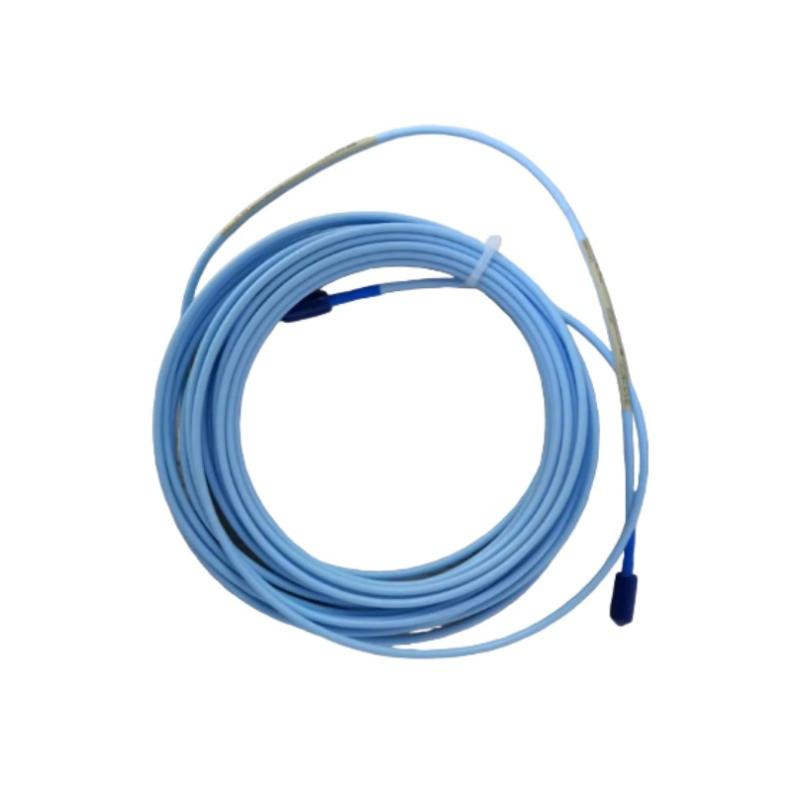
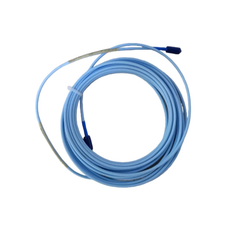
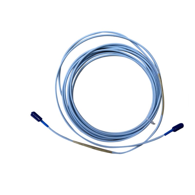
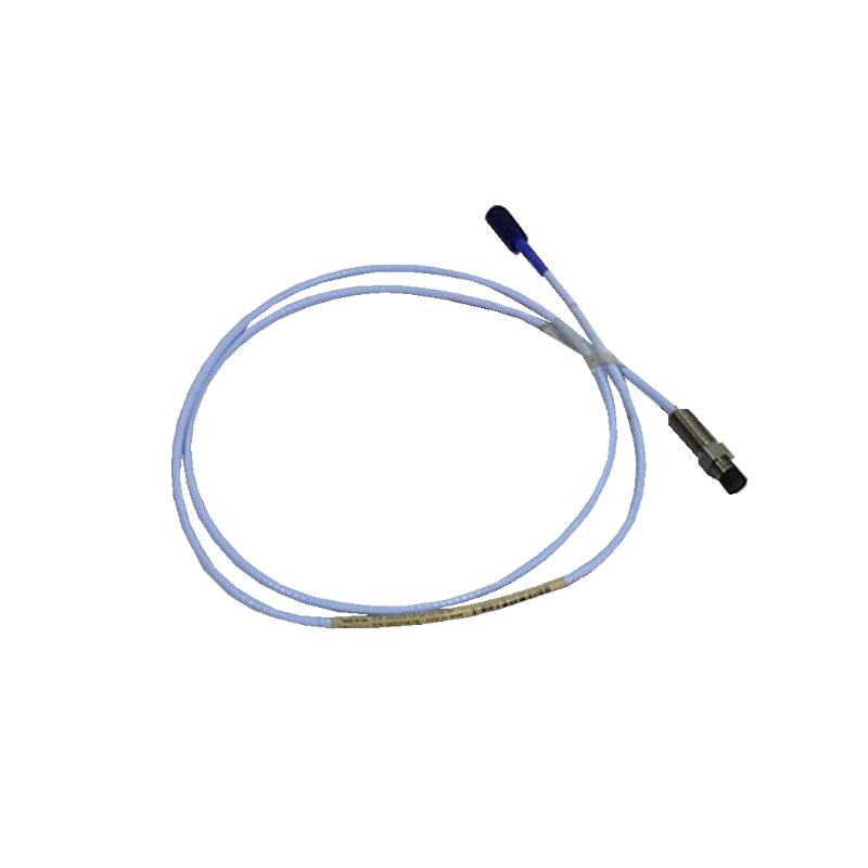
- Bently Nevada
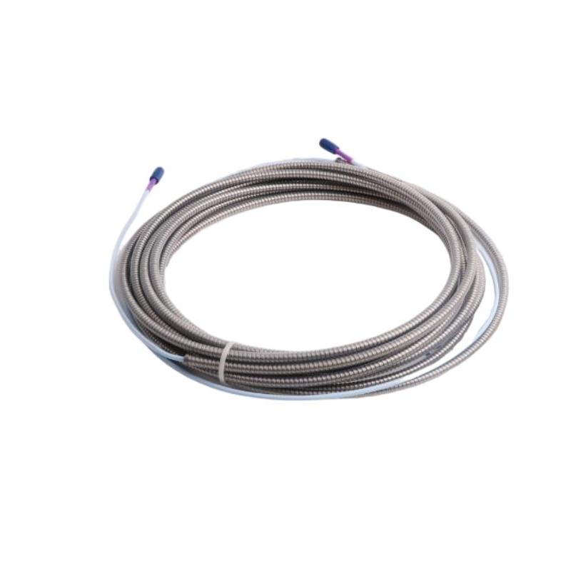
- 330730-040-10-05
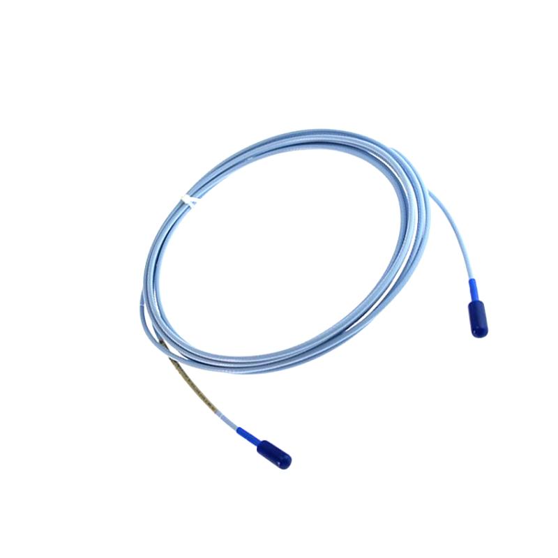
- 3300 XL 11mm Extension Cable
- USA
- 4.0 m
- 1kg
- Xiamen, China
- New & In Stock
- T/T, PayPal, Western Union
- 1 Year
- 1-3 Working Days
- DHL, UPS, TNT, FedEx and EMS.
- 24-Hour Service
- COO
- 3
Our advantage

Global Logistics
We have a 10-year logistics and express cooperation agreement, so our products can be shipped to any place in the world.

Brand new and original
Our products are imported in bulk from the place of origin. Because of the cooperative relationship, our products are all original and 100% new.

24-hour service
We provide 7*24 hours service to our customers. We will be there whenever you need us.

Price advantage
All our products are priced very favorably because we have our own warehouse and supply.
| Company Information | |||
| [email protected] | |||
| Mobile | +8615980777398 | ||
| +8615980777398 | |||
| 15980777398 |
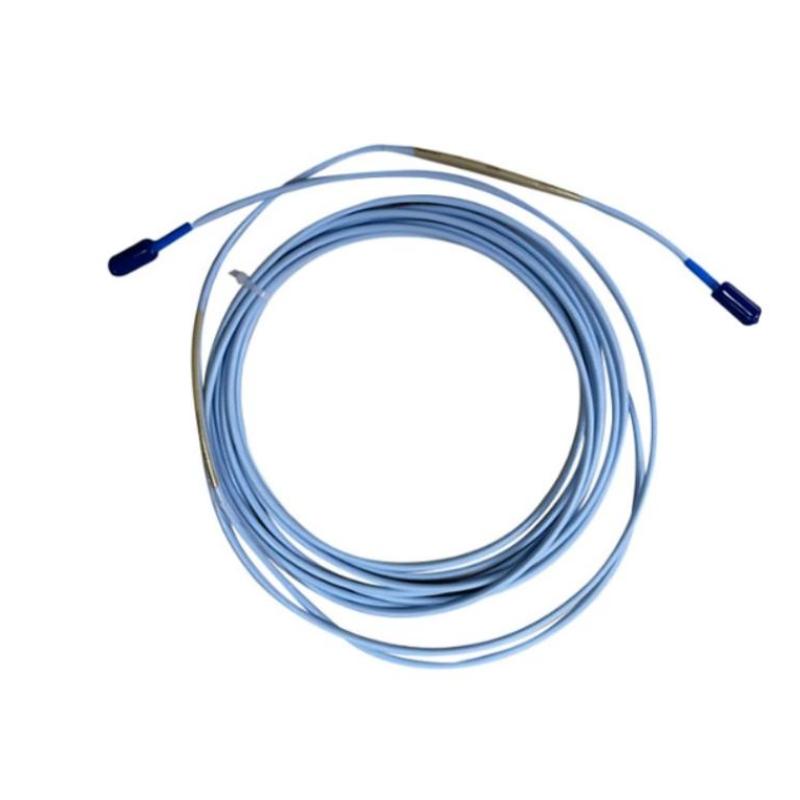
Bently Nevada 330730-040-10-05 — Product Specifications, Description, Applications, Advantages, and Related Models
1. Product Overview
The Bently Nevada 330730-040-10-05 is a model designation associated with the 3300 XL proximity measurement product family. This family is used in industrial machinery monitoring systems to measure shaft vibration and relative displacement when paired with compatible proximity probes, sensor electronics, and monitoring instruments.
The product designation appears to belong to the extension-cable category. An extension cable provides the electrical connection between a proximity probe and its compatible sensor system. Its length, connector configuration, and electrical characteristics must match the rest of the measurement system.
For industrial maintenance and purchasing purposes, the complete ordering code is important. Even when two cables have similar appearances or share most of their model numbers, they may differ in length, connector options, or other construction details.
The exact specification of 330730-040-10-05 has not been independently confirmed here. The information below therefore distinguishes general product-family characteristics from model-specific details that require verification.
2. Product Parameters
| Parameter | Specification |
|---|---|
| Brand | Bently Nevada |
| Model number | 330730-040-10-05 |
| Product series | 3300 XL |
| Product category | Proximity measurement extension cable, subject to confirmation of the complete ordering code |
| Main function | Electrical connection between compatible proximity-system components |
| Measurement principle | Eddy-current proximity measurement, when used in a compatible system |
| Typical monitored quantities | Shaft vibration and relative shaft displacement |
| Typical equipment | Turbines, compressors, pumps, motors, and other rotating machinery |
| Cable length | Requires confirmation from the exact ordering code |
| Cable construction | Not confirmed for this specific designation |
| Connector type | Not confirmed for this specific designation |
| Connector arrangement | Must be verified against the installed system |
| Cable outer diameter | Not confirmed |
| Overall dimensions | Cable length, outer diameter, and connector dimensions require verification |
| Product net weight | Not confirmed |
| Weight unit | kg |
| Operating temperature range | Must be verified against the specification for the exact cable version |
| Electrical characteristics | Must match the associated probe and sensor system |
| Installation method | Routed and secured according to the machinery installation requirements |
| Typical installation location | Between compatible proximity probes and sensor electronics |
| Maintenance requirements | Cable inspection, connector checks, routing inspection, and signal verification |
| Replacement requirements | Correct part number, length, connector configuration, and system compatibility |
Dimensions and weight: The exact physical dimensions and weight of model 330730-040-10-05 cannot be stated reliably without confirming the precise ordering code. For this type of component, the most useful dimensional information is normally the cable length, cable outer diameter, and connector dimensions.
The cable’s net weight should be distinguished from the gross shipping weight. If the information is needed for purchasing, warehouse inventory, or freight calculations, both values should be taken from the records for the exact product rather than estimated from a related model.
3. Product Description
3.1 General description
The 3300 XL product family is designed for industrial proximity measurement and machinery condition monitoring. These systems can be used to observe the movement of a rotating shaft relative to a stationary measurement point.
A proximity probe is installed near a suitable conductive target. As the distance between the probe and the target changes, the probe produces a corresponding electrical response. Compatible sensor electronics process this response and provide a signal for the monitoring equipment.
The extension cable forms part of the electrical connection between these components. Its role is to maintain the intended signal path while allowing the probe and associated electronics to be positioned according to the machinery layout.
3.2 Role within the proximity measurement system
The extension cable is an important system component rather than a generic connecting wire. Its electrical characteristics and configuration must be suitable for the intended probe and sensor electronics.
Selecting the correct cable helps maintain the designed electrical relationship between the measurement components. An incorrect cable length or incompatible connector configuration may prevent the system from operating as intended.
For this reason, model identification should be based on the complete ordering code and the original equipment documentation. A partial model-number match is not enough to establish interchangeability.
3.3 Cable construction and installation
The cable construction must suit the physical and environmental conditions of the installation. Depending on the specific version, relevant considerations may include mechanical protection, connector protection, flexibility, temperature exposure, and resistance to installation-related damage.
In industrial environments, cables may be exposed to vibration, oil, moisture, abrasion, heat, and restricted routing paths. Proper cable routing and securing help reduce mechanical stress and the risk of intermittent electrical connections.
The exact construction of model 330730-040-10-05 should be verified before assigning specific materials, armor characteristics, connector finishes, or environmental ratings to it.
3.4 Contribution to monitoring reliability
The reliability of a proximity measurement channel depends on the complete system. A correctly installed probe cannot provide dependable measurements if the connecting cable is damaged, the connectors are loose, or the system components are incompatible.
A properly specified extension cable supports signal continuity and helps maintain the intended measurement configuration. Routine inspection and accurate spare-parts records make troubleshooting and replacement work easier.
4. Product Applications
4.1 Steam turbines
Steam turbines are used in power generation and industrial process facilities. Proximity measurement systems can monitor shaft vibration and relative shaft position at designated measurement locations.
The extension cable connects compatible measurement components, allowing the monitoring instrument to receive the signal. Trends in shaft vibration and displacement can help engineers identify operating changes that require further investigation.
4.2 Gas turbines
Gas turbines operate under demanding mechanical and thermal conditions. Depending on the machine design, proximity probes may be used to monitor shaft movement as part of the machinery monitoring arrangement.
A correctly specified cable helps maintain the required electrical connection between the probe and its associated electronics. Cable routing, connector security, and environmental suitability are important considerations in these installations.
4.3 Centrifugal compressors
Centrifugal compressors are widely used in industrial processing and other continuous-operation facilities. Shaft vibration monitoring can help maintenance teams assess changes in rotor behavior and investigate possible mechanical problems.
The extension cable supports the signal path between the installed probe and sensor electronics. Correct cable selection and installation help reduce avoidable connection problems.
4.4 Industrial pumps
Large pumps may require vibration or shaft-displacement monitoring, particularly where continuous operation and equipment availability are important.
A compatible extension cable connects the measurement components while allowing the cable to be routed through the available installation space. It should be protected from sharp edges, excessive bending, heat, and mechanical interference.
4.5 Electric motors
Large industrial motors and associated drive equipment may incorporate proximity measurement as part of a machinery monitoring system.
The cable provides the connection between the specified probe and sensor electronics. Its suitability depends on the motor’s monitoring configuration and the requirements of the installed equipment.
4.6 General rotating machinery
The same basic function applies to other rotating machinery that uses compatible proximity measurement systems. Examples include selected process machines, auxiliary drives, and critical industrial equipment.
In all cases, the extension cable must match the intended system configuration. It should not be treated as a universal replacement for cables from other measurement families.
5. Product Advantages
5.1 Supports the intended electrical signal path
A correctly selected extension cable provides the required connection between compatible proximity-system components. Appropriate connector engagement and cable routing help maintain stable electrical continuity.
5.2 Designed for use within a dedicated product family
The 3300 XL family is associated with industrial proximity measurement applications. Selecting the appropriate cable configuration helps integrate the connection into a system designed around compatible probes and sensor electronics.
5.3 Supports continuous machinery monitoring
When installed in a compatible system, the extension cable allows the measurement signal to reach the associated electronics. This supports the monitoring of shaft movement and the collection of operational data.
5.4 Helps simplify maintenance work
Keeping a record of the complete cable model, installation location, and associated monitoring channel makes future replacement work more straightforward.
This is especially useful in facilities with multiple machines and several similar monitoring channels.
5.5 Reduces the risk of incorrect replacement
Verifying the complete model number, cable length, and connector configuration before ordering helps avoid selecting a component that looks similar but is not electrically or mechanically suitable.
5.6 Supports organized spare-parts management
Accurate part-number records help purchasing teams maintain suitable replacement stock and reduce confusion between different cable configurations.
The same records can include verified dimensions, net weight in kilograms, packaging information, and the equipment associated with each cable.
5.7 Contributes to system-level reliability
The extension cable is only one part of the monitoring arrangement. Correct component matching, secure connections, suitable installation, and routine inspection all contribute to reliable operation.
A suitable cable therefore supports the overall performance of the measurement system rather than acting as an independent measuring device.
6. Installation and Maintenance Recommendations
Before installing the cable, verify the complete part number against the original equipment records. Confirm the required cable length, connector arrangement, compatible probe, and sensor configuration.
During installation, avoid excessive tension, sharp bends, crushing, and twisting. Route the cable away from moving machine parts, hot surfaces, sharp edges, and other potential sources of mechanical damage.
Inspect connectors for visible damage or contamination before connecting them. Ensure that the connectors are properly engaged according to the applicable equipment instructions.
After installation, check the monitoring channel for normal signal behavior. If the signal is unstable or missing, inspect the entire measurement path, including the probe, cable, sensor electronics, and monitoring configuration.
For critical machinery, replacement and testing should follow the site’s maintenance procedures and the applicable equipment documentation.
7. Five Related Models and Configurations
The following models are candidates for comparison within the 3300 XL proximity measurement family or its related system components. They are not all direct replacements for 330730-040-10-05.
| Model | Product type | Main parameters | Dimensions | Weight (kg) |
|---|---|---|---|---|
| 330730-040-00-00 | Extension cable configuration | Related cable designation; confirm the exact cable length, connectors, and electrical compatibility | Flexible cable; exact length and diameter require confirmation | Not confirmed |
| 330730-040-03-00 | Extension cable configuration | Related model for cable-configuration comparison; verify ordering-code details | Flexible cable; connector dimensions require confirmation | Not confirmed |
| 330730-040-03-05 | Extension cable configuration | Related designation; confirm compatibility and construction before substituting | Flexible cable; exact dimensions require confirmation | Not confirmed |
| 330730-080-03-00 | Extension cable configuration | Related cable designation; verify required length and connector configuration | Flexible cable; exact dimensions require confirmation | Not confirmed |
| 330130-040-00-00 | Related proximity-system component candidate | Confirm exact product category and full ordering code before selection | Depends on the confirmed component configuration | Not confirmed |
Model selection notes
The first four entries are cable-related comparison candidates. The complete ordering codes must be checked to establish whether their lengths, connector arrangements, and electrical characteristics match the intended installation.
The final entry is included as a related-system comparison candidate rather than a confirmed direct replacement cable. Its exact product type should be verified before procurement.
The dimensions and weights listed above are not confirmed manufacturer values. For a formal technical specification or purchase order, obtain the physical dimensions and net weight for each exact model.
8. Five Additional Models from the Same Brand
The following table lists additional model designations and product categories associated with industrial proximity measurement and machinery monitoring. Their functions differ, so they should not be considered interchangeable with the requested extension cable.
| Model | Product category | Main parameters | Dimensions | Weight (kg) |
|---|---|---|---|---|
| 330106-05-30-10-02-CN | Proximity probe candidate | Probe-related designation; confirm probe size, mounting arrangement, and system compatibility | Depends on the exact probe configuration | Not confirmed |
| 330103-00-07-10-02-CN | Proximity probe candidate | Probe-related designation; confirm length, mounting details, and full ordering code | Depends on the exact probe configuration | Not confirmed |
| 330180-50-00 | Related proximity-system component candidate | Verify exact product function and compatibility with the installed system | Depends on the confirmed component configuration | Not confirmed |
| 3300 XL 11 mm proximity probe system | Proximity measurement system | Compatible probe, extension cable, and sensor electronics used for shaft-displacement measurement | Depends on the selected components | Not confirmed |
| 3300 XL proximity sensor system | Sensor and signal-conditioning equipment | Interfaces with compatible probes and supplies the measurement signal to monitoring equipment | Depends on the exact sensor model | Not confirmed |
The first three entries require confirmation of their exact product category and ordering details before purchase. The final two entries describe product categories rather than complete individual order codes, so exact dimensions and weights depend on the selected components.
For procurement purposes, the full model number should always be recorded. A family name or abbreviated designation is not sufficient to establish the exact specifications of an individual product.
9. Comparison of Main Proximity-System Components
| Component | Main function | Typical installation position | Key selection parameters | Dimensions | Weight (kg) |
|---|---|---|---|---|---|
| 3300 XL extension cable | Connects compatible proximity-system components | Between the probe and sensor electronics | Cable length, connector type, construction, electrical compatibility | Cable length, outer diameter, connector dimensions | Not confirmed |
| 3300 XL proximity probe | Detects changes in distance to a suitable conductive target | Near the monitored shaft or target | Probe diameter, length, mounting thread, tip design, system compatibility | Depends on probe configuration | Not confirmed |
| 3300 XL proximity sensor | Interfaces with the probe and conditions the measurement signal | According to the monitoring-system design | Probe compatibility, electrical characteristics, system configuration | Depends on sensor model | Not confirmed |
| Machinery monitoring instrument | Processes, displays, or records measurement signals | Control cabinet or designated instrument location | Model, input configuration, channel count, monitoring functions | Depends on instrument model | Not confirmed |
These components perform separate functions within the measurement chain. The correct replacement must be selected according to the component being replaced and the requirements of the installed system.
10. Procurement Checklist
Before ordering model 330730-040-10-05, confirm the following details.
1. Complete model number: Check every digit and suffix against the original label or parts list.
2. Cable length: Verify the required length for the existing installation.
3. Connector configuration: Confirm the connector type and end arrangement.
4. System compatibility: Ensure that the cable matches the specified probe and sensor electronics.
5. Cable construction: Check that the construction suits the installation environment.
6. Physical dimensions: Obtain the cable diameter and connector dimensions from the applicable technical drawing.
7. Net weight: Record the actual product weight in kilograms.
8. Packaging information: Record package dimensions and gross shipping weight separately from the cable’s own dimensions and net weight.
9. Operating conditions: Verify the specified temperature range and environmental limitations.
10. Replacement compatibility: Compare the proposed model with the original installed component and its documentation.
11. Final Summary
The Bently Nevada 330730-040-10-05 is a designation associated with the 3300 XL proximity measurement product family and appears to represent an extension-cable configuration. Its intended role is to provide the electrical connection between compatible proximity measurement components.
Its typical applications include shaft monitoring on turbines, compressors, pumps, motors, and other industrial rotating machinery. The principal benefits of a correctly specified cable are support for signal continuity, easier maintenance, and preservation of the intended measurement-system configuration.
The most important selection criteria are the complete ordering code, cable length, connector arrangement, electrical compatibility, construction, and installation conditions.
The exact dimensions and weight in kilograms for this specific designation have not been confirmed. These figures should be obtained from the specification for the exact model rather than inferred from a related cable. Verifying the full part number before procurement will help ensure that the replacement component is suitable for the existing installation.