

ProductPRODUCT
Featured products
Contact Us
- Schneider
- OTB1S0DM9LP
- I/O Distributed Module
- France
- 55 × 90 × 70 mm
- 0.19 kg
- Xiamen, China
- New & In Stock
- T/T, PayPal, Western Union
- 1 Year
- 1-3 Working Days
- DHL, UPS, TNT, FedEx and EMS.
- 24-Hour Service
- COO
- 1
Our advantage

Global Logistics
We have a 10-year logistics and express cooperation agreement, so our products can be shipped to any place in the world.

Brand new and original
Our products are imported in bulk from the place of origin. Because of the cooperative relationship, our products are all original and 100% new.

24-hour service
We provide 7*24 hours service to our customers. We will be there whenever you need us.

Price advantage
All our products are priced very favorably because we have our own warehouse and supply.
| Company Information | |||
| [email protected] | |||
| Mobile | +8615980777398 | ||
| +8615980777398 | |||
| 15980777398 |
Product Overview
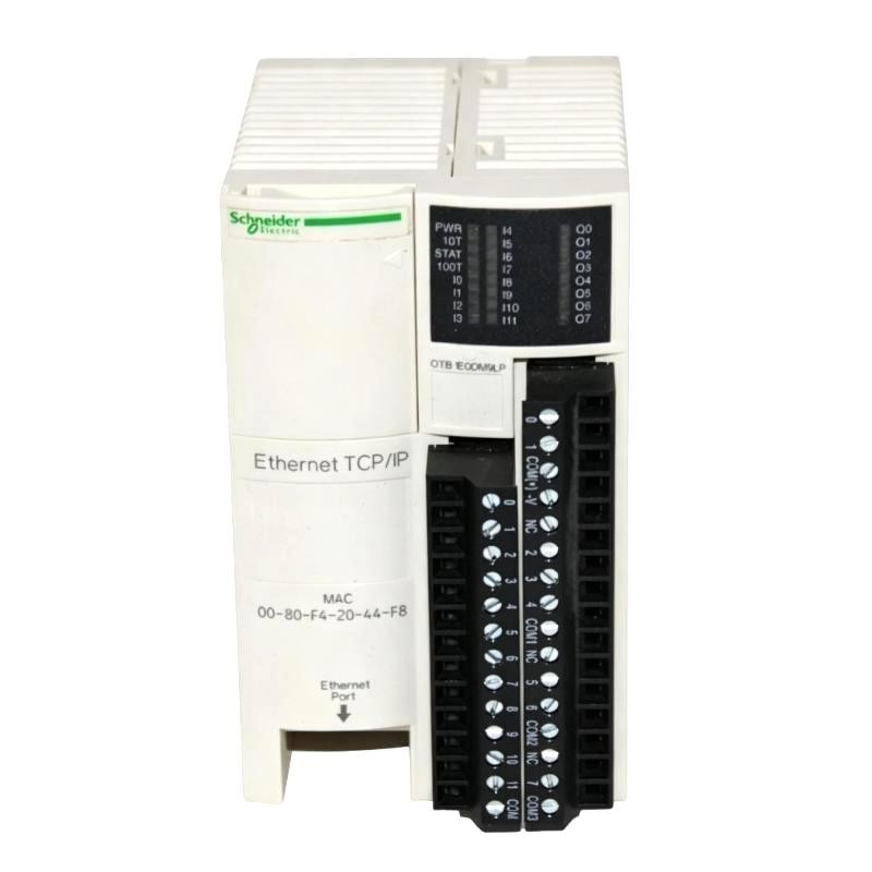
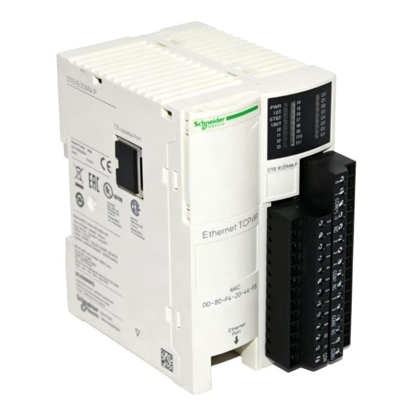
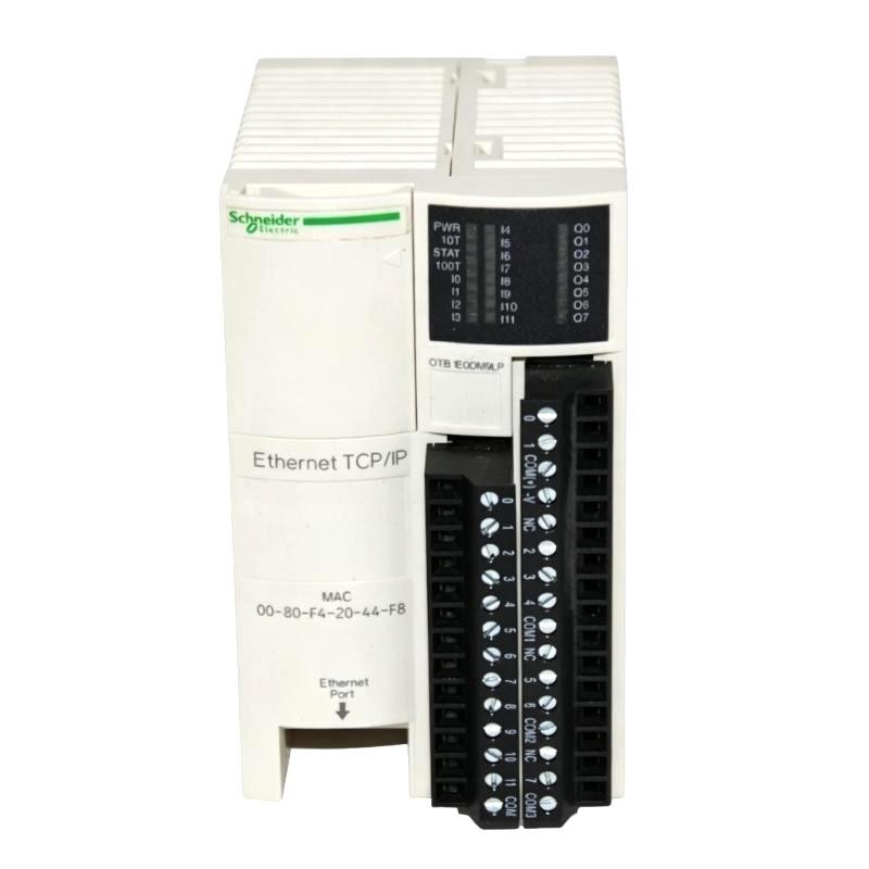
The Schneider Electric OTB1S0DM9LP is an Advantys OTB distributed I/O module with a non-isolated serial communication interface for Modbus networks. It combines 12 digital inputs, two solid-state transistor outputs, and six relay outputs in one module, allowing field signals and control loads to be managed through a shared distributed I/O station.
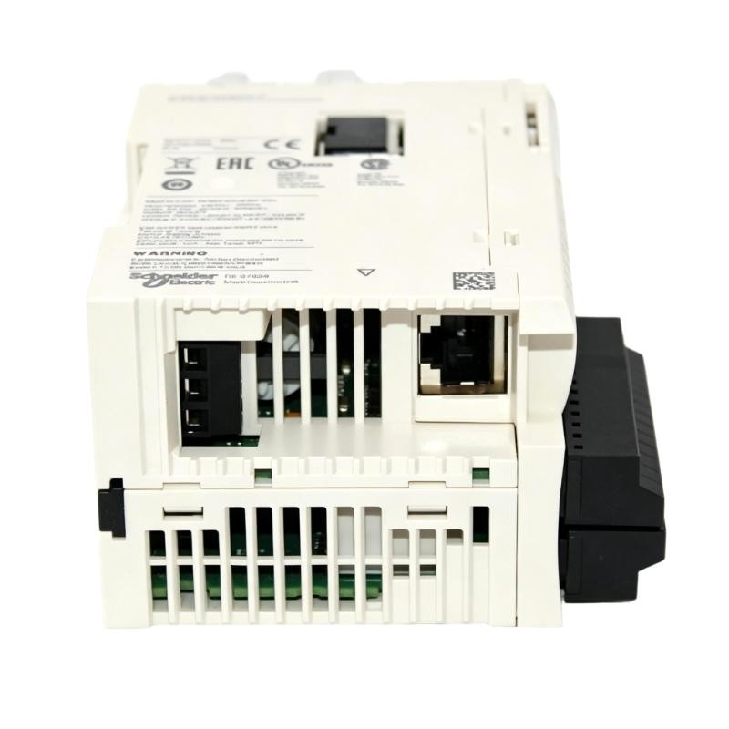
Unlike the Ethernet-based OTB1E0DM9LP, this model communicates through a serial Modbus link using RS-485. The interface supports Modbus RTU and ASCII communication, making it suitable for automation systems built around serial communication between a controller and remote field I/O. The module provides two RJ45 serial connectors wired in parallel, allowing compatible devices to be connected through supported daisy-chain or tap arrangements.
The 12 digital inputs accept compatible 24 V DC field signals from devices such as proximity sensors, limit switches, push buttons, and auxiliary contacts. The input logic supports sink or source wiring arrangements, helping accommodate different field-device output types within the specified electrical limits.
The eight outputs use two different switching technologies. Outputs Q0 and Q1 are PNP source transistor outputs for compatible DC loads, while Q2 through Q7 are relay outputs for suitable AC or DC control circuits. This arrangement allows the module to serve machines where electronic DC switching and relay-based switching are both needed.
A practical example is a packaging machine with sensors monitoring product position, switches detecting mechanical travel, and output signals operating compatible pneumatic valves or interface relays. The module collects the field states and exchanges them with the controller over the serial Modbus network. The controller then processes the signals and sends output commands according to the machine sequence.
The serial communication arrangement is particularly relevant when integrating distributed I/O into an existing Modbus RTU system. The communication speed, data format, parity, addressing, and master/slave configuration must be coordinated with the controller and other devices on the same network. Since the serial interface is non-isolated, the electrical installation and grounding arrangement also require attention.
The OTB1S0DM9LP supports expansion through compatible Advantys OTB I/O modules. Additional channels can be added within the system’s supported configuration and power limits, allowing the field I/O arrangement to be adapted to the machine without changing the basic serial communication approach.
The relay outputs require careful load selection. Although they can switch compatible AC and DC circuits, the current rating of each output and the permitted current per common must be observed. The COM terminals are not internally connected together, so the external wiring must reflect the intended circuit arrangement.
The OTB1S0DM9LP is suited to distributed machine-control applications where serial Modbus communication, mixed digital outputs, and a compact field I/O arrangement are required. Its input logic, output technologies, serial settings, and network topology should all be considered during system design.
Technical Specifications
| Parameter | Specification |
|---|---|
| Manufacturer | Schneider Electric |
| Model | OTB1S0DM9LP |
| Product Family | Advantys OTB |
| Product Type | I/O Distributed Module |
| Integrated Communication Interface | Non-isolated serial link |
| Communication Protocols | Modbus RTU, Modbus ASCII |
| Physical Interface | RS-485 |
| Serial Connectors | 2 × RJ45, connected in parallel |
| Transmission Mode | Half-duplex |
| Baud Rate | 1,200–38,400 bit/s |
| Discrete Inputs | 12 |
| Input Voltage | 24 V DC |
| Input Logic | Sink or source |
| Discrete Outputs | 8 |
| Transistor Outputs | 2, PNP source |
| Relay Outputs | 6 |
| Transistor Output Current | 300 mA rated per output |
| Relay Output Current | 2 A per output |
| Maximum Relay Output Voltage | 240 V AC or 30 V DC |
| Input Voltage Range | 20.4–26.4 V DC |
| Solid-State Output Voltage Range | 20.4–28.8 V DC |
| Maximum Devices per Serial Segment | 32 |
| Protection Rating | IP20 |
| Dimensions | 55 × 90 × 70 mm |
| Weight | 0.19 kg |
Product Features
- Serial Modbus communication: Connects distributed field I/O to compatible controllers using RS-485.
- 12 digital inputs: Collects 24 V DC signals from compatible field sensors and switches.
- Two PNP transistor outputs: Provides electronic switching for suitable DC loads.
- Six relay outputs: Supports switching of compatible AC or DC control circuits.
- Mixed output technologies: Combines solid-state and relay switching within one module.
- Modbus RTU and ASCII support: Accommodates supported serial communication formats.
- Dual RJ45 serial connectors: Provides parallel-connected ports for compatible serial wiring arrangements.
- Sink or source input logic: Supports different input wiring configurations within the specified limits.
- Advantys OTB expansion capability: Supports compatible additional I/O modules within system limits.
- Distributed field control: Allows local field signals to be exchanged with the controller over a serial link.
Working Principle
The OTB1S0DM9LP collects digital field signals, exchanges their states over a serial Modbus connection, and switches connected loads according to commands received from the controller.
Field Sensors and Switches → Digital Inputs → OTB1S0DM9LP → RS-485 Modbus → PLC
PLC Commands → RS-485 Modbus → OTB1S0DM9LP Outputs → Field Loads
The 12 digital input channels receive signals from compatible 24 V DC field devices. When a sensor or switch changes state, the input circuit detects the corresponding electrical condition. The module then makes the input status available through its communication functions for the controller to read.
The input logic supports sink or source arrangements. Field wiring must match the connected device’s output type, polarity, and common arrangement. Input voltage must remain within the specified range so that the module can correctly distinguish valid ON and OFF states.
The serial interface uses RS-485 communication and supports Modbus RTU and ASCII. The controller acts as the communication master in a typical arrangement, requesting input information and sending output commands to the module. The serial parameters, including baud rate, data format, parity, and device addressing, must match the network configuration.
The two transistor outputs use PNP source switching. When commanded on, each output supplies a positive DC signal to its compatible load. Correct polarity and common wiring are essential, and the load current must remain within the output rating. Inductive loads may require suitable suppression to limit switching transients.
The six relay outputs use electromechanical contacts. They can switch compatible AC or DC loads within their specified voltage and current limits. Relay outputs are useful when the connected circuit requires switching characteristics that differ from those of transistor outputs. The COM terminals are not internally connected together, so each output group must be wired according to the intended circuit.
The serial network can connect compatible devices through supported daisy-chain or tap arrangements. The total number of devices, bus length, cable arrangement, and termination practices must follow the applicable RS-485 network design. The module supports up to 32 devices per serial segment under the specified system conditions.
The non-isolated communication interface means that electrical potential differences and grounding arrangements deserve attention when connecting devices across different parts of a machine. Cable routing and grounding should be planned to reduce interference and avoid communication instability.
The module can also operate with compatible Advantys OTB expansion modules. Additional modules increase the available field I/O, while the network interface provides communication with the controller. The complete configuration must remain within the system’s expansion and power limits.
During commissioning, verify the serial communication settings before testing individual I/O points. Check the controller’s Modbus configuration, device address, baud rate, parity, data format, and wiring. Once communication is established, test each input and output against the intended controller logic.
If input states are incorrect, investigate the field-device supply, polarity, channel wiring, and controller mapping. If an output fails to operate, check the output command, load supply, output type, and current limits. Communication errors should be investigated separately from field-wiring faults by checking the serial cable, network topology, and communication parameters.
The OTB1S0DM9LP combines field signal acquisition, mixed output switching, and serial Modbus communication in one distributed I/O module for compatible industrial automation systems.
Role in the Industrial Control Architecture
The OTB1S0DM9LP occupies the field-I/O layer between machine devices and the controller. It gathers local digital signals, operates compatible loads, and exchanges data through a serial Modbus network.
Field Devices → OTB1S0DM9LP → RS-485 Modbus Network → PLC
PLC → RS-485 Modbus Network → OTB1S0DM9LP → Actuators and Control Loads
| System Component | Function |
|---|---|
| Schneider OTB1S0DM9LP | Collects digital inputs, switches outputs, and exchanges Modbus data |
| PLC or Modbus Master | Executes machine logic and communicates with the distributed I/O |
| RS-485 Serial Network | Carries input-state information and output commands |
| Proximity Sensors | Detect the presence or position of machine components |
| Limit Switches | Indicate mechanical end positions |
| Push Buttons | Provide operator commands |
| PNP Transistor Outputs | Switch compatible DC loads electronically |
| Relay Outputs | Switch compatible AC or DC control circuits |
| 24 V DC Power Supply | Supplies the module and associated field circuits as required |
| Interface Relays | Switch loads requiring additional current or contact capacity |
| Compatible OTB Expansion Modules | Add supported I/O channels to the distributed station |
| Circuit Protection Devices | Protect field wiring and connected loads |
The controller executes the application logic, while the OTB1S0DM9LP handles local signal acquisition and output switching. Reliable operation depends on correct serial settings, wiring, and mapping between the controller program and physical I/O channels.
Industrial Applications
| Application | Typical Use |
|---|---|
| Packaging Machinery | Collects product-position signals and operates compatible machine-control loads |
| Conveyor Systems | Monitors product presence, limit switches, and equipment status |
| Assembly Machines | Interfaces with sensors, push buttons, and actuator circuits |
| Material-Handling Equipment | Exchanges field signals over a serial Modbus network |
| Automated Inspection Stations | Collects discrete inspection and machine-state signals |
| Industrial Workcells | Provides local I/O for machines using serial controller communication |
| Palletizing Equipment | Monitors mechanical positions and operates compatible control devices |
| Small Production Machines | Combines field inputs and mixed outputs in one distributed module |
| Process Auxiliary Equipment | Monitors discrete states and switches compatible auxiliary loads |
| Legacy Modbus Installations | Adds distributed I/O to compatible serial communication systems |
Installation and Maintenance
- Verify the model reference: Confirm that the module is OTB1S0DM9LP and that the planned system uses compatible Advantys OTB components.
- Prepare the control cabinet: Install the module in a suitable enclosure and allow adequate access for wiring and maintenance.
- Provide the required power supply: Connect the module and field circuits according to the applicable wiring diagram.
- Wire the RS-485 network: Use a suitable serial cable and follow the supported daisy-chain or tap topology.
- Configure serial communication: Set the baud rate, data format, parity, and addressing to match the Modbus master.
- Identify the field inputs: Label each input and check the sensor voltage, polarity, and sink/source arrangement.
- Separate transistor and relay wiring: Connect each load to the correct output type and observe the terminal and common arrangements.
- Check output-load ratings: Verify the voltage and current of each load against the applicable transistor or relay output limits.
- Provide suitable circuit protection: Install appropriate fuses and suppression components where required, particularly for inductive loads.
- Verify controller mapping: Confirm that each physical input and output corresponds to the intended channel in the PLC program.
- Test communication and I/O: Confirm stable Modbus communication and operate each input and output under controlled conditions.
- Record configuration and maintenance details: Document serial settings, channel assignments, wiring changes, and any faults identified during inspection.
If communication is unstable, check the serial cable, wiring topology, baud rate, parity, device address, and grounding arrangement. If an input is not detected, inspect the sensor supply and input wiring. If an output fails to operate, check the controller command, load circuit, output type, and applicable current limits before replacing the module.
Related Components
| Component | Function |
|---|---|
| Schneider Electric OTB1S0DM9LP | Provides distributed digital I/O and serial Modbus communication |
| Schneider Electric OTB1E0DM9LP | Related Advantys OTB module with Ethernet TCP/IP communication |
| Schneider Electric OTB1C0DM9LP | Related Advantys OTB module with CANopen communication |
| Schneider Electric TM3BCSL | Modicon TM3 serial-line bus coupler |
| Compatible PLC or Modbus Master | Executes control logic and exchanges data with the module |
| 24 V DC Power Supply | Supplies compatible module and field circuits |
| Proximity Sensors | Detect object presence and machine position |
| Limit Switches | Provide discrete mechanical-position signals |
| Interface Relays | Switch loads that exceed the module’s direct output capabilities |
| RS-485 Serial Cable | Connects the module to the Modbus network |
| Circuit Protection Devices | Protect field circuits and connected loads |
| Compatible Advantys OTB Expansion I/O | Adds supported digital or other I/O channels |
Recommended Related Models
| Model / Product Family | Product Type | Typical Application |
|---|---|---|
| Schneider Electric OTB1E0DM9LP | Advantys OTB Distributed I/O Module | Ethernet TCP/IP communication with compatible controllers |
| Schneider Electric OTB1C0DM9LP | Advantys OTB Distributed I/O Module | CANopen communication in compatible distributed I/O systems |
| Schneider Electric TM3BCSL | Modicon TM3 Serial-Line Bus Coupler | Serial communication for compatible Modicon TM3 I/O configurations |
| Schneider Electric Advantys OTB Series | Distributed I/O System | Distributed field signal acquisition and output control |
| Schneider Electric Modicon TM3 Series | Distributed I/O Modules | Expanding compatible Modicon controller I/O configurations |
Key Advantages
- Combines 12 digital inputs, two PNP transistor outputs, and six relay outputs.
- Supports Modbus RTU and ASCII over a non-isolated RS-485 serial interface.
- Provides two parallel-connected RJ45 serial connectors.
- Accommodates compatible 24 V DC input devices using sink or source logic.
- Combines solid-state and relay output technologies for different control loads.
- Supports compatible expansion within the Advantys OTB distributed I/O system.
Technical FAQs
What is the difference between OTB1S0DM9LP and OTB1E0DM9LP?
The OTB1S0DM9LP uses a non-isolated serial RS-485 interface for Modbus RTU and ASCII communication. The OTB1E0DM9LP uses Ethernet TCP/IP communication. Both models share the same basic arrangement of 12 digital inputs, two PNP transistor outputs, and six relay outputs.
Which serial settings must match the Modbus master?
The baud rate, data format, parity, and device addressing must match the network configuration. The OTB1S0DM9LP supports baud rates from 1,200 to 38,400 bit/s. Incorrect settings can prevent communication even when the serial wiring is correct.
Can the relay outputs and transistor outputs switch the same type of load?
Both output types can switch compatible control loads, but their electrical characteristics differ. The transistor outputs are PNP source outputs intended for DC loads, while the relay outputs can switch compatible AC or DC circuits within their specified ratings. Output selection should reflect the load voltage, current, and switching requirements.
What should be considered when connecting several devices to the serial network?
The RS-485 wiring topology, bus length, device count, cable quality, and communication settings must be coordinated. The module supports up to 32 devices per serial segment under the specified conditions. Because the interface is non-isolated, grounding and electrical potential differences between connected devices should also be considered.