

ProductPRODUCT
Featured products
Contact Us
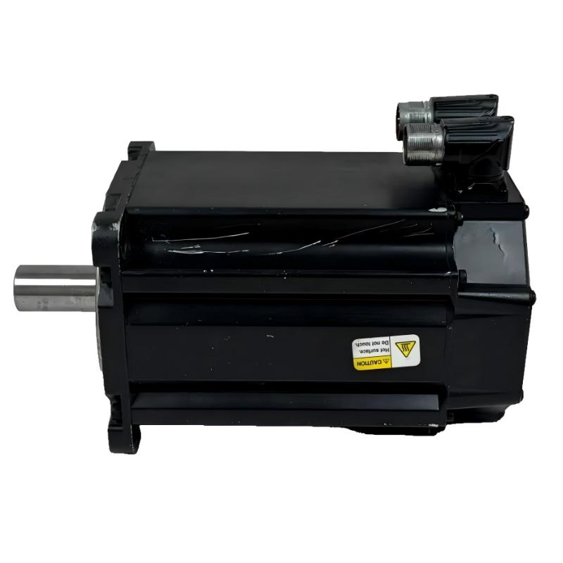
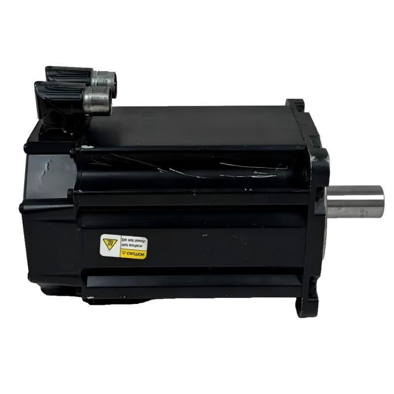
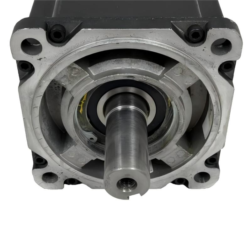
- Allen Bradley
- MPL-B640F-SJ74AA
- Low-Inertia Brushless Servo Motors Product
- USA
- 215 mm × 150 mm × 35 mm
- 30.9 kg
- Xiamen, China
- New & In Stock
- T/T, PayPal, Western Union
- 1 Year
- 1-3 Working Days
- DHL, UPS, TNT, FedEx and EMS.
- 24-Hour Service
- COO
- 28
Our advantage

Global Logistics
We have a 10-year logistics and express cooperation agreement, so our products can be shipped to any place in the world.

Brand new and original
Our products are imported in bulk from the place of origin. Because of the cooperative relationship, our products are all original and 100% new.

24-hour service
We provide 7*24 hours service to our customers. We will be there whenever you need us.

Price advantage
All our products are priced very favorably because we have our own warehouse and supply.
| Company Information | |||
| [email protected] | |||
| Mobile | +8615980777398 | ||
| +8615980777398 | |||
| 15980777398 |
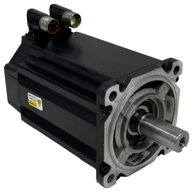
Allen-Bradley MPL-B640F-SJ74AA Servo Motor – Detailed Specifications, Product Introduction, Applications, Advantages and Model Recommendations
The Allen-Bradley MPL-B640F-SJ74AA is a high-performance low-inertia AC rotary servo motor designed for industrial automation and precision motion-control applications.
It belongs to the MP-Series MPL low-inertia brushless servo motor family and is configured with a 460 V class electrical design, 215 mm frame, 101.6 mm magnet stack, 3000 rpm operating class, single-turn high-resolution absolute feedback, keyed shaft, and an integral 24 V DC holding brake.
Compared with the closely related no-brake MPL-B640F-SJ72AA, the most important difference is the integrated brake. This makes the MPL-B640F-SJ74AA especially useful for applications where the motor must hold a load after servo torque is removed, particularly vertical or gravity-loaded machine axes.
The following information is organized around the motor’s technical characteristics, practical machine applications, advantages, installation considerations, and closely related model choices. Where a dimensional or weight figure can vary by configuration or documentation convention, it is identified as approximate rather than presented as an unnecessarily precise value.
1. Basic Product Information
| Parameter | Specification |
|---|---|
| Brand | Allen-Bradley |
| Product Series | MP-Series MPL |
| Product Family | MPL Low-Inertia Brushless Servo Motors |
| Model | MPL-B640F-SJ74AA |
| Product Type | AC Rotary Servo Motor |
| Motor Technology | Brushless Permanent-Magnet Servo |
| Voltage Class | 460 V AC class |
| Rated Speed | 3000 rpm |
| Maximum Speed Class | 3000 rpm |
| Continuous Torque | Approx. 36.7 N·m |
| Peak Torque | Approx. 72.3 N·m |
| Continuous Power | Approx. 6.1 kW |
| Rotor Inertia | Approx. 0.004 kg·m² |
| Feedback | Single-turn high-resolution absolute encoder |
| Feedback Resolution | 1024 Sin/Cos cycles/revolution |
| Feedback Protocol | Hiperface |
| Shaft | Keyed shaft extension |
| Brake | Integral 24 V DC holding brake |
| Connector | SpeedTEC DIN |
| Connector Style | Right-angle |
| Connector Rotation | Approximately 180° |
| Mounting | IEC metric flange |
| Mounting Type | Type FF |
| Mounting Holes | Free mounting holes |
| Bolt Circle | Approximately 215 mm |
| Frame Size | 215 mm |
| Magnet Stack Length | 101.6 mm |
| Dimensions | 215 mm frame × 101.6 mm magnet stack; complete envelope is configuration dependent |
| Weight | Approximately 30.9 kg |
| Motor Construction | Low-inertia |
| Shaft Seal | No standard shaft seal |
2. Brand and Product Series
Brand: Allen-Bradley
Series: MP-Series MPL
Product Family: MPL Low-Inertia Brushless Servo Motors
The MPL-B640F-SJ74AA is part of a servo motor family intended for demanding industrial motion applications.
The MPL family focuses on combining relatively low rotor inertia with high torque capability and high-resolution feedback.
This makes these motors particularly suitable for machinery that performs repeated acceleration, deceleration, indexing, positioning, synchronization, and speed changes.
The MPL-B640F-SJ74AA represents a specific configuration within the family, combining the B640F motor platform with single-turn absolute feedback, a keyed shaft, and an integral 24 V DC brake.
3. Product Introduction
The MPL-B640F-SJ74AA is an industrial AC servo motor intended to operate as part of a closed-loop motion-control system.
Unlike a conventional induction motor that is primarily selected according to horsepower, voltage, and speed, a servo motor is selected according to a much broader group of motion requirements.
These requirements can include:
- Position accuracy
- Speed response
- Acceleration
- Deceleration
- Continuous torque
- Peak torque
- Load inertia
- Feedback resolution
- Mechanical transmission
- Braking requirements
- Machine cycle time
The MPL-B640F-SJ74AA addresses these requirements through a combination of a low-inertia rotor, high-resolution absolute feedback, substantial torque capability, and an integrated holding brake.
The motor provides approximately 36.7 N·m of continuous torque and approximately 72.3 N·m of peak torque, placing it in a relatively substantial industrial servo-motor class.
Its rated speed is approximately 3000 rpm, making it suitable for many general-purpose automation axes where both torque and controlled rotational speed are important.
4. The Most Important Characteristic: Integrated Brake
One of the defining features of the MPL-B640F-SJ74AA is the integrated brake.
| Brake Parameter | Specification |
|---|---|
| Brake | Integral holding brake |
| Brake Voltage | 24 V DC |
| Brake Type | Holding brake |
| Main Purpose | Mechanical holding when required |
| Typical Application | Vertical or gravity-loaded axes |
| Difference from SJ72AA | SJ74AA includes brake; SJ72AA does not |
This feature makes the motor particularly attractive for applications where the machine needs to prevent an axis from moving when the servo motor is not actively producing torque.
A typical example is a vertical positioning axis.
Imagine a machine where the motor drives a vertical ballscrew carrying a heavy assembly.
When the servo is energized, the motor can control the position normally.
If servo torque is removed, however, gravity may cause the mechanical load to move.
A properly controlled motor brake can provide an additional mechanical holding function.
This is one of the major reasons to select the SJ74AA configuration instead of the SJ72AA configuration.
5. Detailed Technical Parameters
| Parameter | MPL-B640F-SJ74AA |
|---|---|
| Model | MPL-B640F-SJ74AA |
| Brand | Allen-Bradley |
| Series | MP-Series MPL |
| Motor Family | MPL Low-Inertia Brushless Servo |
| Motor Type | AC Rotary Servo Motor |
| Voltage | 460 V AC class |
| Speed | 3000 rpm |
| Continuous Torque | Approx. 36.7 N·m |
| Peak Torque | Approx. 72.3 N·m |
| Continuous Power | Approx. 6.1 kW |
| Rotor Inertia | Approx. 0.004 kg·m² |
| Feedback | Single-turn absolute |
| Encoder | High-resolution absolute encoder |
| Feedback Resolution | 1024 Sin/Cos cycles/rev |
| Feedback Protocol | Hiperface |
| Shaft | Keyed |
| Brake | 24 V DC integral holding brake |
| Connector | SpeedTEC DIN |
| Connector Style | Right-angle |
| Connector Rotation | Approx. 180° |
| Frame | 215 mm |
| Magnet Stack | 101.6 mm |
| Mounting | IEC metric flange |
| Mounting Type | Type FF |
| Bolt Circle | Approx. 215 mm |
| Dimensions | 215 mm frame × 101.6 mm stack |
| Weight | Approx. 30.9 kg |
| Shaft Seal | No standard shaft seal |
| Motor Design | Low-inertia |
| Feedback Configuration | Single-turn absolute |
6. Motor Dimensions
The basic mechanical configuration uses a 215 mm frame with a 101.6 mm magnet stack.
| Dimension Parameter | Approximate Value |
|---|---|
| Frame Dimension | 215 mm |
| Frame Equivalent | 8.46 in. |
| Magnet Stack Length | 101.6 mm |
| Magnet Stack Equivalent | 4.0 in. |
| Bolt Circle | Approx. 215 mm |
| Mounting Standard | IEC metric |
| Mounting Configuration | Type FF |
| Shaft | Keyed |
| Connector | Right-angle SpeedTEC DIN |
| Connector Rotation | Approx. 180° |
| Overall Installed Envelope | Configuration dependent |
| Motor Weight | Approx. 30.9 kg |
The 215 mm × 101.6 mm figures should be understood as the principal frame and magnet-stack dimensions rather than a complete three-dimensional shipping-envelope measurement.
For an actual replacement or machine design, the shaft extension, flange, connector position, mounting clearance, cable bend radius, and brake wiring should also be considered.
7. Weight
The motor weight is approximately 30.9 kg.
| Weight Information | Value |
|---|---|
| Motor Weight | Approx. 30.9 kg |
| Approximate Weight in lb | 68.2 lb |
| Weight Category | Heavy industrial servo motor |
The actual packaged shipping weight can be higher because packaging materials, cables, connectors, accessories, and protective materials may not be included in the motor-only weight.
The approximately 30.9 kg motor weight should be considered when designing the motor mounting structure.
This is especially important for:
- Vertical machine axes
- Robotic structures
- Large positioning tables
- Moving machine assemblies
- Overhead installations
- Service and maintenance procedures
8. Torque Performance
The MPL-B640F-SJ74AA provides approximately 36.7 N·m continuous torque and approximately 72.3 N·m peak torque.
| Torque Characteristic | Approximate Value |
|---|---|
| Continuous Torque | 36.7 N·m |
| Peak Torque | 72.3 N·m |
| Peak / Continuous Ratio | Approx. 1.97 |
| Rated Speed | 3000 rpm |
The continuous torque rating represents the motor’s capability during normal sustained operation under appropriate operating conditions.
The peak torque capability is more important during dynamic operation.
For example, when a machine accelerates a heavy load from zero speed to operating speed, the required torque can temporarily be much higher than the steady-state torque.
The same applies to rapid deceleration and direction changes.
This makes the peak torque rating particularly important for:
- Indexing machines
- Pick-and-place equipment
- High-cycle packaging machinery
- Rotary tables
- Transfer systems
- Acceleration-heavy machine axes
9. Low-Inertia Rotor Design
The motor has a low rotor inertia of approximately 0.004 kg·m².
| Inertia Parameter | Approximate Value |
|---|---|
| Rotor Inertia | 0.004 kg·m² |
| Motor Design | Low-inertia |
| Main Benefit | Fast dynamic response |
Low rotor inertia is valuable because the motor does not have to spend as much of its available torque accelerating its own rotor.
More of the available torque can therefore be used to accelerate the external machine load.
This can result in:
- Faster acceleration
- Faster deceleration
- Quicker positioning
- Shorter machine cycles
- Faster direction changes
- Better dynamic response
The final machine response still depends on the complete system.
A machine with excessive load inertia, flexible couplings, poor mechanical alignment, or unsuitable servo tuning may not achieve the theoretical response of the motor alone.
10. Single-Turn Absolute Encoder
The MPL-B640F-SJ74AA uses a single-turn high-resolution absolute encoder.
| Feedback Parameter | Specification |
|---|---|
| Feedback Type | Absolute |
| Feedback Configuration | Single-turn |
| Encoder Type | High-resolution |
| Resolution | 1024 Sin/Cos cycles/revolution |
| Protocol | Hiperface |
| Main Function | Position and speed feedback |
The encoder allows the servo system to monitor the motor shaft position.
The servo drive uses this information to regulate motor operation.
During a positioning move, the controller commands a target position.
The motor begins moving.
The encoder provides actual shaft-position information.
The servo system compares actual and commanded position and adjusts motor torque accordingly.
This closed-loop process is fundamental to high-performance servo control.
11. Single-Turn Versus Multi-Turn
One of the closest alternatives to the MPL-B640F-SJ74AA is a multi-turn configuration.
| Feature | MPL-B640F-SJ74AA | MPL-B640F-MJ74AA |
|---|---|---|
| Feedback | Single-turn absolute | Multi-turn absolute |
| Shaft | Keyed | Keyed |
| Brake | 24 V DC | 24 V DC |
| Speed | 3000 rpm | 3000 rpm |
| Continuous Torque | Approx. 36.7 N·m | Approx. 36.7 N·m |
| Peak Torque | Approx. 72.3 N·m | Approx. 72.3 N·m |
| Frame | 215 mm | 215 mm |
| Stack | 101.6 mm | 101.6 mm |
| Weight | Approx. 30.9 kg | Approx. 30.9 kg |
The main selection difference is therefore the feedback arrangement.
The single-turn version is suitable when the machine’s position requirements can be managed within a single revolution and the system’s reference strategy.
The multi-turn version becomes more attractive when the control system needs to distinguish shaft position across multiple revolutions.
12. Keyed Shaft
The motor uses a keyed shaft.
This provides a familiar mechanical connection for industrial equipment.
Potential mechanical connections include:
- Gearboxes
- Couplings
- Pulleys
- Rollers
- Timing mechanisms
- Indexing mechanisms
- Belt drives
- Gear-driven assemblies
The keyed shaft is particularly useful when replacing a motor in an existing machine that already uses conventional keyed mechanical components.
Correct shaft alignment remains extremely important.
The motor should not be forced into alignment by the coupling or transmission.
Misalignment can create excessive radial or axial loads and may shorten bearing life.
13. Integral 24 V DC Brake
The brake is one of the most significant features of the model.
The brake is designed primarily as a holding mechanism.
It should not be treated as a substitute for all machine safety functions.
| Brake Characteristic | Description |
|---|---|
| Brake Type | Integral holding brake |
| Voltage | 24 V DC |
| Primary Function | Hold the motor shaft when required |
| Major Application | Vertical/gravity-loaded axes |
| Electrical Requirement | Dedicated brake control |
| Mechanical Requirement | Correct brake timing and load management |
A brake-equipped motor can be particularly useful when the motor drives a load that could move due to gravity after motor torque is removed.
Examples include:
- Vertical lifting axes
- Vertical positioning tables
- Z-axis machinery
- Elevating mechanisms
- Lift systems
- Vertical transfer equipment
14. Brake Control Considerations
The brake should be integrated into the machine’s control system correctly.
A typical sequence for a servo-controlled vertical axis may involve:
- Servo drive establishes control.
- Motor torque is established.
- Brake is released.
- Axis begins movement.
- Servo maintains position during motion.
- Axis stops at the target position.
- Servo establishes the required holding condition.
- Brake engages when appropriate.
The exact sequence depends on the drive, controller, mechanical system, safety architecture, and application.
Improper brake timing can cause:
- Load movement
- Mechanical shock
- Position errors
- Brake wear
- Excessive motor torque
- Unexpected axis movement
15. Main Applications
15.1 Vertical Positioning Axes
This is one of the strongest application areas for the brake-equipped version.
The motor can be used for:
- Z-axis positioning
- Vertical transfer
- Lifting mechanisms
- Vertical tooling
- Elevating platforms
- Automated vertical slides
The integral brake provides an additional mechanical holding function when the axis is stopped.
15.2 Packaging Machinery
The motor can also be used in packaging equipment.
Typical applications include:
- Product positioning
- Film feeding
- Cutting
- Sealing
- Indexing
- Labeling
- Cartoning
- Transfer mechanisms
The low-inertia design is helpful for machines with frequent acceleration and deceleration.
15.3 Automated Assembly Equipment
Assembly systems frequently require accurate positioning and repeatable movement.
Potential applications include:
- Component insertion
- Vertical assembly tools
- Indexing stations
- Transfer mechanisms
- Part positioning
- Automated inspection
The brake can be especially useful on vertical tooling or lifting axes.
15.4 Material Handling
The motor can be applied to:
- Vertical transfer systems
- Lifting equipment
- Positioning mechanisms
- Automated conveyors
- Transfer units
- Pallet handling
- Storage and retrieval machinery
The exact suitability depends on load, speed, acceleration, duty cycle, and mechanical transmission.
15.5 Machine Tools
Potential uses include:
- Vertical positioning
- Auxiliary axes
- Automated tooling
- Material positioning
- Feed mechanisms
The brake-equipped configuration can be particularly useful where a vertical axis needs additional holding capability.
15.6 Printing and Converting
Potential applications include:
- Feed mechanisms
- Cutting systems
- Web handling
- Roller control
- Registration
- Positioning
High-resolution feedback is useful where accurate synchronization is required.
15.7 Rotary Indexing
Rotary indexing systems repeatedly accelerate, decelerate, and stop.
The motor’s low-inertia design and peak torque capability are well suited to this operating pattern.
Typical applications include:
- Rotary assembly stations
- Inspection tables
- Filling systems
- Packaging stations
- Machining transfer systems
16. Application Suitability Table
| Application | Suitability | Main Reason |
|---|---|---|
| Vertical Axis | Excellent | Integral holding brake |
| Packaging Machine | Excellent | Low inertia and high dynamic response |
| Assembly Machine | Excellent | Precise closed-loop positioning |
| Rotary Indexer | Excellent | High peak torque and fast response |
| Material Handling | Very Good | Torque and brake capability |
| Machine Tool | Very Good | Precision positioning |
| Printing Machine | Very Good | Feedback and speed control |
| Converting Machine | Very Good | Synchronized motion |
| Horizontal Conveyor | Very Good | Servo control and keyed shaft |
| Lifting Mechanism | Excellent | Brake-equipped configuration |
17. Major Product Advantages
17.1 Integrated Holding Brake
The biggest advantage compared with the no-brake version is the integral 24 V DC brake.
This makes the motor more suitable for applications where the shaft needs to be held mechanically.
17.2 Low Rotor Inertia
The low-inertia design allows the motor to respond rapidly to motion commands.
This is valuable in high-cycle machines.
17.3 High Continuous Torque
Approximately 36.7 N·m continuous torque provides strong continuous mechanical output.
This allows the motor to handle substantial machine loads when correctly sized.
17.4 High Peak Torque
Approximately 72.3 N·m peak torque gives the system additional dynamic capability.
This is important for acceleration and short-duration load changes.
17.5 High-Resolution Absolute Feedback
The single-turn absolute encoder provides detailed shaft-position information.
This supports accurate:
- Positioning
- Speed regulation
- Synchronization
- Indexing
- Motion control
17.6 Keyed Mechanical Interface
The keyed shaft makes the motor compatible with many conventional industrial transmission components.
17.7 3000 rpm Speed Class
A 3000 rpm configuration provides a useful balance between torque and rotational speed for many industrial automation applications.
17.8 Flexible Connector Arrangement
The right-angle SpeedTEC DIN connector and approximately 180° rotation provide useful installation flexibility.
This is particularly helpful when the motor is installed in a compact machine enclosure.
18. Five Closely Related Models
The following five models are useful alternatives or comparison models within the same general MPL family.
| Model | Feedback | Shaft | Brake | Speed | Continuous Torque | Peak Torque | Dimensions | Weight |
|---|---|---|---|---|---|---|---|---|
| MPL-B640F-SJ72AA | Single-turn absolute | Keyed | No brake | 3000 rpm | Approx. 36.7 N·m | Approx. 72.3 N·m | 215 mm × 101.6 mm | Approx. 30.9 kg |
| MPL-B640F-MJ72AA | Multi-turn absolute | Keyed | No brake | 3000 rpm | Approx. 36.7 N·m | Approx. 72.3 N·m | 215 mm × 101.6 mm | Approx. 30.9 kg |
| MPL-B640F-SJ74AA | Single-turn absolute | Keyed | 24 V DC | 3000 rpm | Approx. 36.7 N·m | Approx. 72.3 N·m | 215 mm × 101.6 mm | Approx. 30.9 kg |
| MPL-B640F-MJ74AA | Multi-turn absolute | Keyed | 24 V DC | 3000 rpm | Approx. 36.7 N·m | Approx. 72.3 N·m | 215 mm × 101.6 mm | Approx. 30.9 kg |
| MPL-B660F-SJ72AA | Single-turn absolute | Keyed | No brake | 3000 rpm class | Higher-output configuration | Higher-output configuration | 215 mm × 152.4 mm class | Approx. 32–35 kg class |
The B640F models are the closest comparisons because they share the same basic mechanical platform.
The B660F configuration becomes more interesting when the machine requires a higher-output configuration within a similar frame class.
19. Detailed Comparison of the B640F Models
| Parameter | MPL-B640F-SJ72AA | MPL-B640F-MJ72AA | MPL-B640F-SJ74AA | MPL-B640F-MJ74AA |
|---|---|---|---|---|
| Frame | 215 mm | 215 mm | 215 mm | 215 mm |
| Magnet Stack | 101.6 mm | 101.6 mm | 101.6 mm | 101.6 mm |
| Speed | 3000 rpm | 3000 rpm | 3000 rpm | 3000 rpm |
| Continuous Torque | 36.7 N·m | 36.7 N·m | 36.7 N·m | 36.7 N·m |
| Peak Torque | 72.3 N·m | 72.3 N·m | 72.3 N·m | 72.3 N·m |
| Feedback | Single-turn | Multi-turn | Single-turn | Multi-turn |
| Shaft | Keyed | Keyed | Keyed | Keyed |
| Brake | None | None | 24 V DC | 24 V DC |
| Connector | SpeedTEC DIN | SpeedTEC DIN | SpeedTEC DIN | SpeedTEC DIN |
| Dimensions | 215 × 101.6 mm | 215 × 101.6 mm | 215 × 101.6 mm | 215 × 101.6 mm |
| Weight | Approx. 30.9 kg | Approx. 30.9 kg | Approx. 30.9 kg | Approx. 30.9 kg |
This comparison makes the selection logic relatively simple.
If the machine needs single-turn feedback and no brake, the SJ72AA configuration is the natural choice.
If it needs single-turn feedback and a holding brake, the SJ74AA configuration is more appropriate.
If the machine needs multi-turn feedback, the corresponding MJ configuration becomes the relevant choice.
20. Five Commonly Compared Models from the Same Brand
The following models can be considered useful comparison choices from the same brand and related servo-motor range.
| Model | Series | Speed | Continuous Torque | Peak Torque | Feedback | Shaft | Brake | Dimensions | Weight |
|---|---|---|---|---|---|---|---|---|---|
| MPL-B580J-SJ72AA | MP-Series MPL | 3750 rpm class | Approx. 34 N·m | Approx. 87 N·m | Single-turn absolute | Keyed | No brake | 165 mm × 203.2 mm | Approx. 30–34 kg |
| MPL-B580J-SJ74AA | MP-Series MPL | 3750 rpm class | Approx. 34 N·m | Approx. 87 N·m | Single-turn absolute | Keyed | 24 V DC | 165 mm × 203.2 mm | Approx. 30–34 kg |
| MPL-B580J-MJ72AA | MP-Series MPL | 3750 rpm class | Approx. 34 N·m | Approx. 87 N·m | Multi-turn absolute | Keyed | No brake | 165 mm × 203.2 mm | Approx. 30–34 kg |
| MPL-B640F-SJ72AA | MP-Series MPL | 3000 rpm | Approx. 36.7 N·m | Approx. 72.3 N·m | Single-turn absolute | Keyed | No brake | 215 mm × 101.6 mm | Approx. 30.9 kg |
| MPL-B640F-MJ74AA | MP-Series MPL | 3000 rpm | Approx. 36.7 N·m | Approx. 72.3 N·m | Multi-turn absolute | Keyed | 24 V DC | 215 mm × 101.6 mm | Approx. 30.9 kg |
These are best understood as commonly compared or useful related models, rather than as a strict ranking of sales popularity.
21. B580J Compared with B640F
The B580J and B640F families have noticeably different mechanical proportions.
| Parameter | MPL-B580J Series | MPL-B640F Series |
|---|---|---|
| Frame Dimension | 165 mm | 215 mm |
| Stack Length | 203.2 mm | 101.6 mm |
| Speed Class | 3750 rpm | 3000 rpm |
| Continuous Torque | Approx. 34 N·m | Approx. 36.7 N·m |
| Peak Torque | Approx. 87 N·m | Approx. 72.3 N·m |
| Feedback | Single / Multi-turn | Single / Multi-turn |
| Brake Options | Configuration dependent | Configuration dependent |
| Shaft | Configuration dependent | Keyed |
| Weight | Approx. 30–34 kg class | Approx. 30.9 kg |
| Mechanical Character | Smaller frame, longer stack | Larger frame, shorter stack |
The B580J family can be attractive when higher rotational speed and high dynamic torque are priorities.
The B640F family is more attractive when the application calls for a larger frame with strong continuous torque and a shorter axial stack.
22. Why Choose the MPL-B640F-SJ74AA Instead of the SJ72AA?
This is an important selection question.
| Requirement | MPL-B640F-SJ72AA | MPL-B640F-SJ74AA |
|---|---|---|
| Single-turn feedback | Yes | Yes |
| Keyed shaft | Yes | Yes |
| 3000 rpm | Yes | Yes |
| Approx. 36.7 N·m continuous torque | Yes | Yes |
| Approx. 72.3 N·m peak torque | Yes | Yes |
| Integral brake | No | Yes |
| Vertical axis suitability | More limited | Better suited |
| Horizontal axis | Excellent | Excellent |
| Brake wiring | Not required | Required |
| Mechanical holding function | No motor brake | Integral brake |
If the machine has no requirement for a holding brake, the SJ72AA can be simpler.
If the machine has a vertical load or another condition requiring shaft holding, the SJ74AA becomes much more attractive.
23. Vertical-Axis Applications
The brake-equipped design is particularly useful in vertical-axis applications.
Consider a machine with a vertical ballscrew.
The servo motor rotates the ballscrew.
The ballscrew moves a carriage vertically.
The carriage may carry a substantial load.
When the servo is operating, the motor can control the load position.
When the machine stops, however, the load may still be affected by gravity.
The integrated brake provides a mechanical holding function that can help prevent unwanted movement when properly integrated into the machine control and safety design.
Potential vertical-axis applications include:
- Z-axis positioning
- Vertical presses
- Automated lifts
- Tool positioning
- Vertical transfer stations
- Elevator-style machine mechanisms
- Pick-and-place vertical axes
24. Packaging Machine Applications
In packaging equipment, the motor can be used where rapid and repeatable movement is required.
Examples include:
- Product feeding
- Product indexing
- Film feeding
- Cutting
- Sealing
- Label positioning
- Carton positioning
- Rotary indexing
The low-inertia design can help shorten acceleration and deceleration periods.
The encoder provides feedback for accurate motion.
The brake can be useful where a vertical mechanism needs to remain in position during a machine stop.
25. Automated Assembly Applications
Assembly machines often combine horizontal and vertical axes.
For example, a machine may:
- Move a component horizontally.
- Position it accurately.
- Move a tool downward.
- Perform an assembly operation.
- Raise the tool.
- Return to the next position.
The vertical axis can benefit from a brake-equipped servo configuration.
The low-inertia motor design can also support rapid repetitive cycles.
26. Machine Tool Applications
Machine tools often require precise positioning and controlled speed.
The motor can be considered for:
- Feed axes
- Vertical axes
- Auxiliary positioning
- Automatic tooling mechanisms
- Material positioning
The exact suitability depends on the machine’s required torque, speed, acceleration, load inertia, and control architecture.
27. Material Handling Applications
Material-handling systems frequently require controlled movement of heavy objects.
The MPL-B640F-SJ74AA can be considered for:
- Vertical transfer
- Lifting
- Positioning
- Conveyor indexing
- Pallet positioning
- Transfer units
- Automated storage mechanisms
The brake is especially relevant where the machine load can move due to gravity.
28. Electrical and Mechanical Integration
The motor should be treated as part of a complete servo system.
A typical arrangement includes:
Motion Controller → Servo Drive → MPL-B640F-SJ74AA → Mechanical Transmission → Machine Load
The encoder provides feedback from the motor back to the servo-control system.
The brake provides an additional mechanical holding function.
The complete system therefore involves several separate functions:
| System Element | Function |
|---|---|
| Controller | Generates motion commands |
| Servo Drive | Controls motor current and motion |
| Motor | Converts electrical energy into mechanical rotation |
| Encoder | Measures motor position |
| Brake | Provides mechanical holding |
| Coupling | Transfers torque |
| Gearbox | Changes speed/torque when required |
| Ballscrew/Belt/Gear | Transfers motion |
| Load | Performs the machine operation |
29. Installation Considerations
Before installing an MPL-B640F-SJ74AA, verify the mechanical and electrical requirements.
Important checks include:
- Motor voltage
- Servo drive compatibility
- Encoder compatibility
- Feedback wiring
- Brake voltage
- Brake control circuit
- Shaft dimensions
- Keyway
- Coupling
- Flange
- Mounting holes
- Motor weight
- Cable routing
- Cooling conditions
- Machine load
The brake wiring deserves special attention.
Because the motor includes a 24 V DC brake, the machine control system must be designed to operate the brake correctly.
30. Maintenance
The motor should be inspected as part of normal machine maintenance.
| Maintenance Area | Inspection Item |
|---|---|
| Motor Mounting | Check mounting bolts |
| Shaft | Check for wear |
| Keyway | Check for looseness |
| Coupling | Check alignment |
| Encoder Cable | Check for damage |
| Brake Wiring | Check connection and insulation |
| Connector | Check condition |
| Bearings | Check abnormal noise |
| Motor Housing | Check abnormal temperature |
| Machine Load | Check increased mechanical resistance |
| Servo Performance | Check positioning and following errors |
Unexpected vibration does not automatically mean that the motor itself is defective.
Potential causes can include:
- Mechanical misalignment
- Coupling problems
- Bearing problems
- Gearbox wear
- Excessive load inertia
- Mechanical resonance
- Poor servo tuning
- Loose mounting
- Damaged transmission components
31. Main Advantages Summary
| Feature | Advantage |
|---|---|
| Low-Inertia Rotor | Fast acceleration and deceleration |
| 36.7 N·m Continuous Torque | Strong continuous output |
| 72.3 N·m Peak Torque | Strong dynamic performance |
| 3000 rpm | Good general industrial speed class |
| Single-Turn Absolute Encoder | Accurate position feedback |
| 1024 Sin/Cos Cycles | High-resolution feedback |
| Keyed Shaft | Conventional mechanical connection |
| 24 V DC Brake | Mechanical holding capability |
| 215 mm Frame | High-capacity industrial construction |
| 101.6 mm Stack | Relatively short axial motor configuration |
| SpeedTEC DIN Connector | Industrial connection arrangement |
| Rotatable Connector | Flexible installation |
| Approx. 30.9 kg | Robust industrial motor construction |
32. Selection Guide
| Machine Requirement | Recommended Model |
|---|---|
| Single-turn + keyed + no brake | MPL-B640F-SJ72AA |
| Single-turn + keyed + 24 V brake | MPL-B640F-SJ74AA |
| Multi-turn + keyed + no brake | MPL-B640F-MJ72AA |
| Multi-turn + keyed + 24 V brake | MPL-B640F-MJ74AA |
| Higher-output configuration | MPL-B660F Series |
| Higher-speed configuration | MPL-B580J Series |
For a machine requiring single-turn absolute feedback plus a holding brake, the MPL-B640F-SJ74AA is the most direct choice among these configurations.
33. Important Replacement Checks
If the MPL-B640F-SJ74AA is being used as a replacement motor, do not compare the model number alone.
The following specifications should be checked against the existing motor:
| Replacement Parameter | MPL-B640F-SJ74AA |
|---|---|
| Voltage Class | 460 V |
| Frame | 215 mm |
| Stack | 101.6 mm |
| Speed | 3000 rpm |
| Continuous Torque | Approx. 36.7 N·m |
| Peak Torque | Approx. 72.3 N·m |
| Feedback | Single-turn absolute |
| Shaft | Keyed |
| Brake | 24 V DC |
| Connector | SpeedTEC DIN |
| Mounting | IEC metric |
| Dimensions | 215 mm frame × 101.6 mm stack |
| Weight | Approx. 30.9 kg |
Particular attention should be given to the brake.
Replacing a brake-equipped motor with a no-brake motor can create a serious difference in machine behavior, especially on vertical axes.
Similarly, replacing a single-turn feedback motor with a multi-turn motor or vice versa should only be done after confirming compatibility with the motion-control system.
34. Overall Product Evaluation
The Allen-Bradley MPL-B640F-SJ74AA is best viewed as a relatively high-capacity, low-inertia industrial servo motor designed for applications where accurate closed-loop motion and mechanical holding capability are both important.
Its combination of approximately 36.7 N·m continuous torque, approximately 72.3 N·m peak torque, and a 3000 rpm speed class provides a useful balance for many industrial automation applications.
The low-inertia rotor helps improve dynamic response.
The single-turn high-resolution absolute encoder provides accurate shaft feedback.
The keyed shaft provides a conventional mechanical interface.
The integral 24 V DC brake adds an important mechanical holding capability.
This makes the motor particularly attractive for machines that combine high-cycle servo motion with vertical or gravity-loaded mechanisms.
35. Final Summary
The Allen-Bradley MPL-B640F-SJ74AA belongs to the MP-Series MPL Low-Inertia Brushless Servo Motor family.
Its primary configuration can be summarized as:
460 V class
215 mm frame
101.6 mm magnet stack
3000 rpm
Approximately 36.7 N·m continuous torque
Approximately 72.3 N·m peak torque
Approximately 0.004 kg·m² rotor inertia
Single-turn high-resolution absolute encoder
1024 Sin/Cos cycles/revolution
Hiperface feedback
Keyed shaft
24 V DC integral holding brake
SpeedTEC DIN right-angle connector
Approximately 215 mm × 101.6 mm principal dimensions
Approximately 30.9 kg
The biggest practical advantage of the MPL-B640F-SJ74AA over the closely related MPL-B640F-SJ72AA is the integrated holding brake.
For a horizontal axis that never needs mechanical holding, the no-brake version may be sufficient.
For a vertical axis, lifting mechanism, vertical positioning stage, or another gravity-loaded system, the brake-equipped MPL-B640F-SJ74AA can be the more appropriate configuration.
Its low-inertia construction, substantial torque capability, high-resolution absolute feedback, keyed shaft, and integrated brake make it a versatile choice for packaging machinery, automated assembly, material handling, machine tools, rotary indexing equipment, printing and converting systems, and other industrial motion-control applications.
For quick identification, the model can be remembered as:
MPL-B640F-SJ74AA = B640F 3000 rpm platform + Single-turn absolute feedback + Keyed shaft + 24 V DC brake.
The closest configuration choices are:
MPL-B640F-SJ72AA — single-turn, keyed, no brake
MPL-B640F-MJ72AA — multi-turn, keyed, no brake
MPL-B640F-MJ74AA — multi-turn, keyed, 24 V DC brake
MPL-B580J series — higher-speed related MPL configuration
MPL-B660F series — higher-output related MPL configuration
For applications where precise servo motion and reliable mechanical holding are both important, the MPL-B640F-SJ74AA is a particularly useful configuration within the MPL servo motor family.