

ProductPRODUCT
Featured products
Contact Us
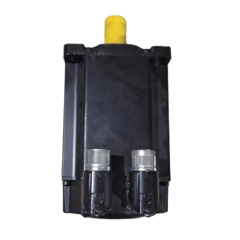
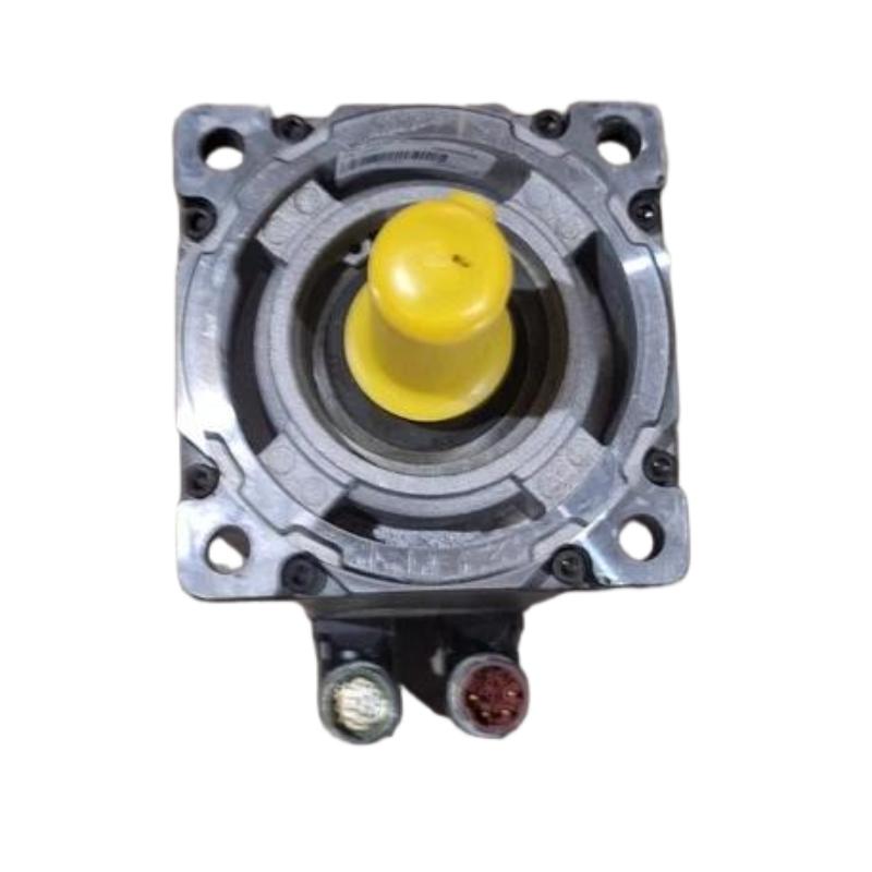
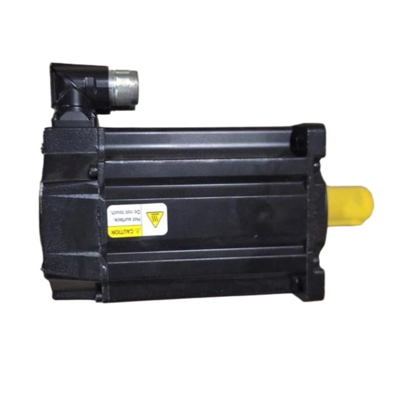
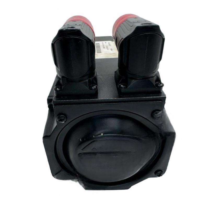
- Allen Bradley
- MPL-B310P-HK72AA
- Servo Motor
- USA
- 100 mm
- 2.7 kg
- Xiamen, China
- New & In Stock
- T/T, PayPal, Western Union
- 1 Year
- 1-3 Working Days
- DHL, UPS, TNT, FedEx and EMS.
- 24-Hour Service
- COO
- 4
Our advantage

Global Logistics
We have a 10-year logistics and express cooperation agreement, so our products can be shipped to any place in the world.

Brand new and original
Our products are imported in bulk from the place of origin. Because of the cooperative relationship, our products are all original and 100% new.

24-hour service
We provide 7*24 hours service to our customers. We will be there whenever you need us.

Price advantage
All our products are priced very favorably because we have our own warehouse and supply.
| Company Information | |||
| [email protected] | |||
| Mobile | +8615980777398 | ||
| +8615980777398 | |||
| 15980777398 |
Product Overview
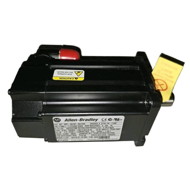
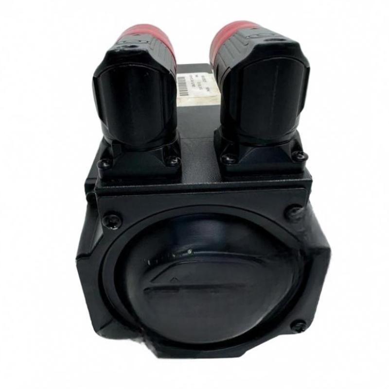
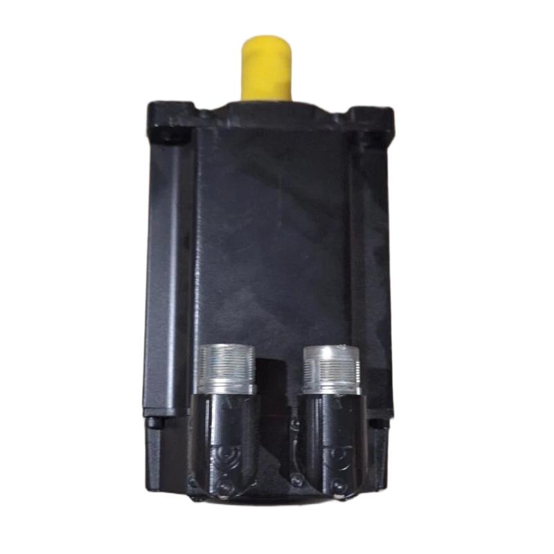
The Allen Bradley MPL-B310P-HK72AA Servo Motor is an industrial motion-control component designed for applications requiring controlled rotational movement, accurate positioning, and coordinated machine operation. As part of the Allen-Bradley Kinetix motion-control ecosystem, MPL-series servo motors are used in compatible automation systems where repeatable motion, responsive acceleration, and dependable motor performance are important.
Servo motors differ from conventional induction motors because they are designed to operate as part of a closed-loop motion-control system. A compatible servo drive regulates motor current and torque while using feedback information to control speed and position. This arrangement enables automated equipment to perform coordinated movements according to programmed motion profiles.
The MPL-B310P-HK72AA is identified by the supplied product description as an Allen-Bradley servo motor with a 100 mm frame size and a weight of 2.7 kg. Its compact construction is suitable for consideration in machinery where installation space, mechanical alignment, and motor integration are important design factors.
Typical servo motor applications include packaging machinery, automated assembly equipment, material handling systems, indexing mechanisms, and other industrial machines that require controlled movement. Actual suitability depends on the motor’s verified electrical characteristics, torque requirements, feedback configuration, mechanical interface, and compatibility with the selected servo drive.
When selecting or replacing this motor, users should confirm the complete catalog number and revision details against the existing installation. Similar-looking servo motors can differ in winding characteristics, feedback devices, shaft design, connector arrangement, and drive compatibility.
Technical Specifications
| Parameter | Specification |
|---|---|
| Manufacturer | Allen-Bradley |
| Brand Owner | Rockwell Automation |
| Model / Catalog Number | MPL-B310P-HK72AA |
| Product Type | AC Servo Motor |
| Product Series | MPL Servo Motor Family |
| Frame Size | 100 mm |
| Weight | 2.7 kg |
| Primary Function | Controlled rotary motion for industrial automation |
| Control Method | Closed-loop servo control when paired with compatible equipment |
| Drive Requirement | Compatible servo drive selected according to the exact motor specifications |
| Feedback Interface | Verify from the complete catalog number and motor documentation |
| Mechanical Mounting | Confirm flange, shaft, and mounting dimensions before installation |
| Typical Applications | Packaging, assembly, positioning, indexing, and material handling |
| Replacement Requirement | Verify catalog number, electrical characteristics, feedback, and mechanical fit |
The table includes the product identification and physical information supplied for this model. Rated voltage, continuous and peak torque, rated speed, power output, shaft dimensions, connector orientation, brake configuration, and feedback type should be confirmed from the exact product documentation rather than inferred from the model name.
What Is the Allen Bradley MPL-B310P-HK72AA Servo Motor?
A servo motor is an electromechanical device used to produce controlled movement in an automated system. Unlike a motor operated only through a basic start-and-stop circuit, a servo motor normally works with a servo drive and feedback system to achieve a commanded position, speed, or torque.
In an industrial machine, the controller generates a motion command. The servo drive interprets this command and supplies regulated electrical power to the motor. Feedback from the motion system allows the drive or controller to compare the actual movement with the requested movement and make corrections as necessary.
This coordinated operation is particularly valuable when machinery must position components accurately, follow repeatable movement sequences, or synchronize multiple axes.
The MPL-B310P-HK72AA is described as a servo motor within the Allen-Bradley MPL family. Its role in a complete motion-control system depends on the matched drive, feedback interface, controller, mechanical transmission, and application requirements.
A simplified motion-control arrangement is:
PLC or Motion Controller → Servo Drive → MPL-B310P-HK72AA Motor → Mechanical Load
Feedback information is returned through the supported feedback path so that the motion-control system can regulate operation.
Function and Working Principle
1. Motion Command Generation
The motion controller defines the required movement according to the machine program. A command may specify a target position, velocity, acceleration, deceleration, or a coordinated motion sequence.
For example, a packaging machine may require a component to move to a defined position before the next production step begins. The controller generates the motion command and coordinates the movement with the machine’s other operations.
2. Servo Drive Power Regulation
The compatible servo drive converts the incoming electrical supply into controlled motor power. It regulates the current delivered to the motor according to the required torque and motion profile.
The drive must be selected for the exact motor model. Incorrect drive sizing or an incompatible motor configuration can cause commissioning difficulties, performance limitations, or equipment faults.
3. Electromagnetic Torque Production
When the servo drive energizes the motor windings, electromagnetic forces generate rotational torque. This torque drives the connected mechanical load through the motor shaft and any associated coupling, gearbox, belt, or transmission mechanism.
The available torque and speed depend on the motor’s rated characteristics, the drive configuration, operating conditions, and mechanical load.
4. Feedback and Motion Regulation
A closed-loop servo system uses feedback to determine how the motor is operating relative to the commanded movement. The drive or controller can correct deviations by adjusting the motor’s electrical input.
The exact feedback device and interface supported by the MPL-B310P-HK72AA should be verified using its complete catalog number and technical documentation.
5. Coordinated Machine Movement
In multi-axis machinery, servo motors may operate together under a motion controller. Properly configured axes can coordinate position and speed to support synchronized production processes.
The resulting motion performance depends on the entire system, including motor selection, drive tuning, controller configuration, feedback integrity, and mechanical rigidity.
Role in Industrial Automation Systems
The Allen-Bradley MPL-B310P-HK72AA can serve as the rotary actuator within a compatible servo motion-control system. Its primary purpose is to convert regulated electrical power into controlled mechanical movement.
A typical installation contains several cooperating components:
| System Component | Function |
|---|---|
| PLC or Motion Controller | Executes machine logic and generates motion commands |
| Compatible Servo Drive | Regulates motor power and executes configured servo control |
| MPL-B310P-HK72AA Servo Motor | Produces rotational motion |
| Feedback Device | Provides motion information through the supported interface |
| Motor Power Cable | Supplies motor power from the drive |
| Feedback Cable | Carries supported feedback signals |
| Mechanical Coupling | Connects the motor shaft to the driven equipment |
| Gearbox or Transmission | Adjusts speed and torque where required |
| HMI Panel | Displays machine status, alarms, and operator controls |
| Industrial Network | Exchanges commands and status data where supported |
The actual configuration depends on the machine design. The availability and type of feedback, brake, connector, and communication interfaces must be established from the exact motor and drive specifications.
Industrial Applications
Packaging and Processing Machinery
Packaging equipment frequently requires controlled positioning, repeatable indexing, and coordinated movement. Servo systems can operate feed mechanisms, positioning axes, and other rotary functions where motion accuracy and repeatability are important.
The appropriate motor must be selected according to the required torque, speed, acceleration, duty cycle, and mechanical load.
Automated Assembly Systems
Assembly machinery may use servo motors to position components, move fixtures, and coordinate mechanical operations. Programmable motion profiles help equipment perform repeatable movement sequences while supporting flexible production requirements.
Material Handling Equipment
Servo motors can be incorporated into suitable material handling systems for controlled movement, indexing, and positioning. The mechanical transmission and motor sizing must account for load inertia, friction, acceleration, and expected operating cycles.
Printing and Converting Equipment
Printing, labeling, and converting machines can use servo motion systems to coordinate rollers, feed mechanisms, and positioning axes. Accurate synchronization between motion axes can help maintain consistent material handling and process timing.
Industrial Automation Machinery
Special-purpose machines may use servo motors for rotary tables, pick-and-place mechanisms, indexing stations, and other controlled-motion applications. Actual suitability depends on the motor’s verified performance envelope and the requirements of the application.
Robotics and Multi-Axis Equipment
Servo technology is commonly used in automated positioning systems and coordinated axes. Whether this specific motor is suitable for a particular robotic or multi-axis installation depends on its torque, speed, feedback, mounting, and drive compatibility.
Installation and Mechanical Integration
Correct installation helps protect the motor and maintain reliable motion performance.
Confirm the Motor Identity
Before installation, check the nameplate and complete catalog number: MPL-B310P-HK72AA. Confirm that the replacement matches the original motor’s electrical and mechanical requirements.
Do not assume that another MPL-series motor is interchangeable simply because its frame size is similar.
Check Mounting Dimensions
The supplied frame size is 100 mm. Before mounting, verify the actual flange dimensions, mounting-hole pattern, shaft diameter, shaft length, keyway or other shaft features, and permitted installation orientation.
Frame size alone does not establish full mechanical interchangeability.
Inspect the Motor Shaft and Coupling
Check the motor shaft and coupling for contamination, damage, excessive wear, and alignment problems. Incorrect coupling alignment can increase bearing loads and vibration, reducing service life.
The coupling must be suitable for the motor shaft and the driven load. Follow the specified installation tolerances and coupling manufacturer’s instructions.
Assess the Mechanical Load
Calculate or verify the load requirements before commissioning. Important factors include:
- Load inertia
- Required acceleration and deceleration
- Operating speed
- Continuous and peak torque requirements
- Duty cycle
- Transmission ratio
- Mechanical friction
- Expected operating temperature
A motor that is too small for the application may experience excessive current, overheating, or motion faults. An incorrectly selected motor may also reduce dynamic performance.
Electrical Installation and Drive Compatibility
Servo motors require a compatible drive and correctly selected cabling. Electrical integration should follow the exact motor and drive documentation.
Verify Drive Compatibility
Confirm that the selected servo drive supports the complete MPL-B310P-HK72AA catalog number or its specified motor configuration. Check the motor’s rated voltage, current, torque, speed, feedback interface, and any other configuration requirements.
Do not select a drive based only on brand or frame size.
Use the Correct Motor Cables
Motor power cables and feedback cables must match the motor’s connector configuration and the selected drive. Inspect cables for damaged insulation, bent contacts, loose connections, and signs of moisture or contamination.
Route motor and feedback cables according to the system’s grounding and electromagnetic-compatibility requirements. Suitable cable separation and shielding practices can help reduce electrical interference.
Grounding and Electrical Protection
Ensure that protective grounding and electrical protection are implemented according to the applicable equipment specifications and local regulations. Verify the installation before energizing the drive.
All electrical work should be performed by qualified personnel using approved isolation and lockout procedures.
Configure the Motion System
Enter the correct motor identification and parameters in the supported drive or controller configuration. Verify the selected feedback settings, operating limits, motion profile, and fault-response behavior.
Incorrect motor data or incompatible configuration settings can cause poor performance, failure to enable, or repeated drive faults.
Commissioning Procedure
A structured commissioning process helps establish safe and predictable operation.
Step 1: Inspect the installation. Confirm motor mounting, coupling alignment, cable connections, grounding, and mechanical clearance.
Step 2: Verify the electrical configuration. Check the motor and drive identification, cable compatibility, protective devices, and configured motor parameters.
Step 3: Confirm feedback operation. Where the system uses motor feedback, verify that the configured interface operates correctly and that the controller or drive receives valid information.
Step 4: Check the mechanical load. Ensure that the driven equipment can move freely within its intended operating range and that no unexpected obstruction is present.
Step 5: Perform an initial motion test. Use the approved commissioning procedure and an appropriate low-risk operating condition to confirm the direction and basic response of the motor.
Step 6: Verify motion performance. Check acceleration, deceleration, stopping behavior, position response, and any application-specific synchronization requirements.
Step 7: Record baseline information. Document drive parameters, alarm history, operating conditions, and commissioning results to support future maintenance.
The actual sequence and precautions should follow the instructions for the installed motor, servo drive, controller, and machine.
Troubleshooting the MPL-B310P-HK72AA Servo Motor
Servo motor faults can originate from the motor, drive, feedback system, cabling, controller, mechanical load, or parameter configuration. A systematic diagnosis helps avoid unnecessary component replacement.
Motor Does Not Rotate
Possible causes include:
- Servo drive not enabled
- Missing or incorrect power connections
- Active drive fault
- Incorrect motor configuration
- Feedback fault
- Motion command not being generated
- Mechanical obstruction
- Incorrect controller or drive configuration
Review the drive’s diagnostic information first. Confirm that the controller is issuing the intended command and that the drive is permitted to operate. Check wiring and configuration against the applicable documentation.
Motor Overheating
Potential causes include excessive mechanical load, frequent high-acceleration cycles, poor ventilation, incorrect motor sizing, unsuitable drive parameters, or a mechanical problem.
Compare actual operating conditions with the motor’s rated limits. Inspect the driven mechanism for excessive friction or binding and verify that the drive configuration matches the motor.
Do not continue operating a motor that exhibits abnormal overheating until the cause has been investigated.
Positioning Errors
Positioning problems may result from incorrect feedback configuration, loose mechanical couplings, excessive load inertia, unsuitable motion settings, mechanical backlash, or a problem in the motion-control system.
Check the mechanical transmission first, then review the feedback status and motion configuration. Compare commanded and actual movement using the diagnostic facilities available in the installed system.
Excessive Vibration or Noise
Unusual vibration or noise can be associated with misalignment, worn bearings, mechanical resonance, loose mounting hardware, damaged couplings, or inappropriate motion settings.
Inspect the mounting and transmission system and compare the behavior with the equipment’s normal operating condition. Avoid disassembling the motor unless the applicable maintenance procedure authorizes the work.
Drive Reports a Feedback Fault
A feedback-related fault may be caused by a damaged cable, loose connector, incorrect feedback configuration, electrical interference, or a fault in the feedback device or associated electronics.
Inspect the cable and connectors, verify the configured feedback interface, and review the drive’s diagnostic messages. Use the precise motor and drive documentation to identify the supported checks.
Intermittent Motion Faults
Intermittent faults can arise from loose electrical connections, cable damage, unstable power, mechanical overload, overheating, or sporadic interference.
Record the operating conditions and fault history when the issue occurs. Check whether the fault correlates with movement, load changes, temperature, or vibration. This information can help distinguish electrical, mechanical, and configuration-related causes.
Preventive Maintenance Recommendations
Regular inspection can help maintain dependable servo operation.
Inspect the Motor and Mounting
Check the motor housing, mounting hardware, shaft coupling, and surrounding installation for damage, looseness, or signs of abnormal vibration.
Maintain Cable Integrity
Inspect power and feedback cables for abrasion, crushing, excessive bending, damaged shielding, and loose connectors. Replace damaged cables with suitable approved parts.
Monitor Operating Conditions
Observe motor temperature, drive alarms, current behavior, and motion performance using the diagnostic functions available in the installed system.
Check Mechanical Alignment
Misalignment can increase vibration and mechanical loading. Inspect couplings, gearboxes, and driven mechanisms according to the equipment maintenance schedule.
Review Drive Diagnostics
Retain fault records and relevant operating data. Repeated alarms can indicate an underlying load, wiring, feedback, or configuration problem that should be addressed rather than repeatedly reset.
Keep the Installation Environment Suitable
Maintain the environmental conditions required by the motor and drive. Protect the equipment from contamination, moisture, excessive temperature, and other conditions outside its specified operating limits.
Compatible System Components
The MPL-B310P-HK72AA is intended for use in a suitable servo motion-control arrangement. The following component categories describe the functional elements commonly required in such a system; they do not confirm compatibility with every specific catalog number.
| Component Category | Purpose |
|---|---|
| Compatible Allen-Bradley Servo Drive | Regulates motor power and executes servo control |
| Compatible Motion Controller | Generates and coordinates motion commands |
| Motor Power Cable | Connects the motor to the servo drive |
| Feedback Cable | Carries supported feedback information |
| Industrial Controller or PLC | Coordinates machine logic and motion-related operations |
| HMI Panel | Provides operator controls and diagnostic displays |
| Mechanical Coupling | Transfers motor torque to the load |
| Gearbox or Transmission | Adjusts torque and speed where required |
| Protective Electrical Components | Provide the required electrical isolation and protection |
| Engineering Software | Supports configuration, commissioning, and troubleshooting |
Before purchasing any associated component, verify its compatibility with the exact motor catalog number, the selected servo drive, the installed controller, and the system’s electrical and mechanical requirements.
Replacement and Procurement Considerations
When sourcing an Allen-Bradley MPL-B310P-HK72AA servo motor, accurate identification is essential.
Confirm the following details before ordering:
- Full catalog number: MPL-B310P-HK72AA
- Manufacturer and product family
- Nameplate information and hardware identification
- Frame size and mounting interface
- Shaft dimensions and coupling requirements
- Rated electrical characteristics
- Rated and peak torque requirements
- Feedback configuration
- Connector arrangement
- Brake configuration, if applicable
- Compatibility with the installed servo drive
- Condition, testing status, and storage history
The supplied physical specifications are a 100 mm frame size and a 2.7 kg weight. These values can support preliminary installation planning and inventory management, but they are not sufficient by themselves to establish electrical or mechanical interchangeability.
For replacement projects, compare the complete catalog number and motor nameplate with the original equipment records. Any proposed alternative should be checked for performance, feedback, drive compatibility, and mechanical fit before installation.
Key Advantages of Servo Motor Technology
Controlled Motion
A properly configured servo system provides controlled rotational movement for applications requiring defined speed, position, or torque behavior.
Repeatable Operation
Feedback-based motion control can support repeatable machine cycles when the motor, drive, controller, and mechanics are correctly selected and configured.
Flexible Motion Profiles
Servo systems can be programmed to follow application-specific acceleration, deceleration, and movement sequences, subject to the capabilities of the complete system.
Integration with Industrial Automation
Compatible servo motors can operate as part of a larger automation system that combines PLC logic, motion control, operator interfaces, and machine feedback.
Compact Physical Design
The listed 100 mm frame size and 2.7 kg weight provide useful reference information for preliminary mechanical planning. Final fit must be confirmed from the motor’s dimensional drawing.
Technical FAQs
What is the Allen Bradley MPL-B310P-HK72AA?
It is identified as an Allen-Bradley MPL-series AC servo motor intended for controlled motion applications in compatible industrial automation systems.
What is the frame size of this servo motor?
The supplied frame size is 100 mm.
How much does the MPL-B310P-HK72AA weigh?
The supplied weight is 2.7 kg.
Does this servo motor operate without a servo drive?
For normal servo operation, the motor requires a compatible drive and an appropriate control arrangement. The drive regulates the electrical power delivered to the motor.
What applications can use this motor?
Potential applications include packaging machinery, automated assembly, indexing equipment, material handling, and other industrial systems requiring controlled rotary motion. Final suitability depends on verified motor ratings and application load requirements.
Which servo drive is compatible with the MPL-B310P-HK72AA?
The exact drive must be selected using the motor’s complete catalog number and electrical specifications. Voltage, current, torque, feedback, and configuration requirements should all be checked before selection.
What causes a servo motor to fail to start?
Common causes include a disabled drive, active faults, incorrect configuration, wiring problems, invalid feedback, a missing motion command, or mechanical obstruction. Drive diagnostics and a systematic inspection of the entire motion system are useful first steps.
Can another MPL-series motor replace this model?
Not automatically. The replacement must match the required electrical characteristics, feedback interface, shaft and mounting dimensions, drive configuration, and application performance requirements.
How can the service life of this motor be improved?
Correct motor sizing, proper installation, good cable management, appropriate drive tuning, mechanical alignment, and routine inspection can help reduce unnecessary stress and support reliable operation.
Conclusion
The Allen Bradley MPL-B310P-HK72AA Servo Motor is a motion-control component identified for use in compatible industrial automation applications. Paired with a suitable servo drive and motion controller, a servo motor can provide controlled rotation for positioning, indexing, synchronized movement, and repeatable machine operations.
With a supplied 100 mm frame size and a weight of 2.7 kg, the MPL-B310P-HK72AA offers useful physical reference information for equipment planning and replacement evaluation. Successful integration depends on more than physical dimensions: the motor’s electrical ratings, feedback interface, shaft configuration, mechanical load, and drive compatibility must also be verified.
For procurement, installation, or maintenance, confirm the complete catalog number and the applicable technical documentation before selecting associated components or carrying out replacement work. Proper system matching, commissioning, and preventive maintenance help support dependable motion performance and long-term industrial equipment reliability.