

ProductPRODUCT
Featured products
Contact Us
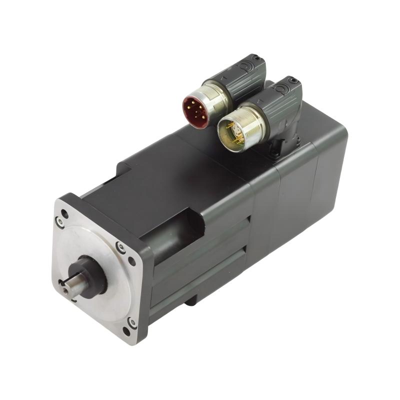
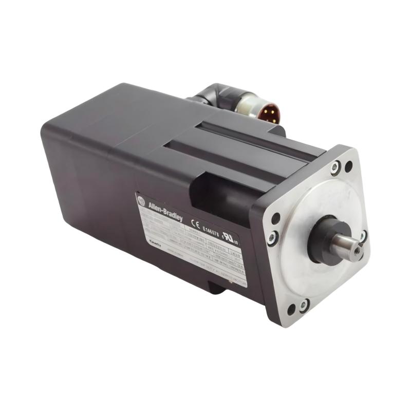
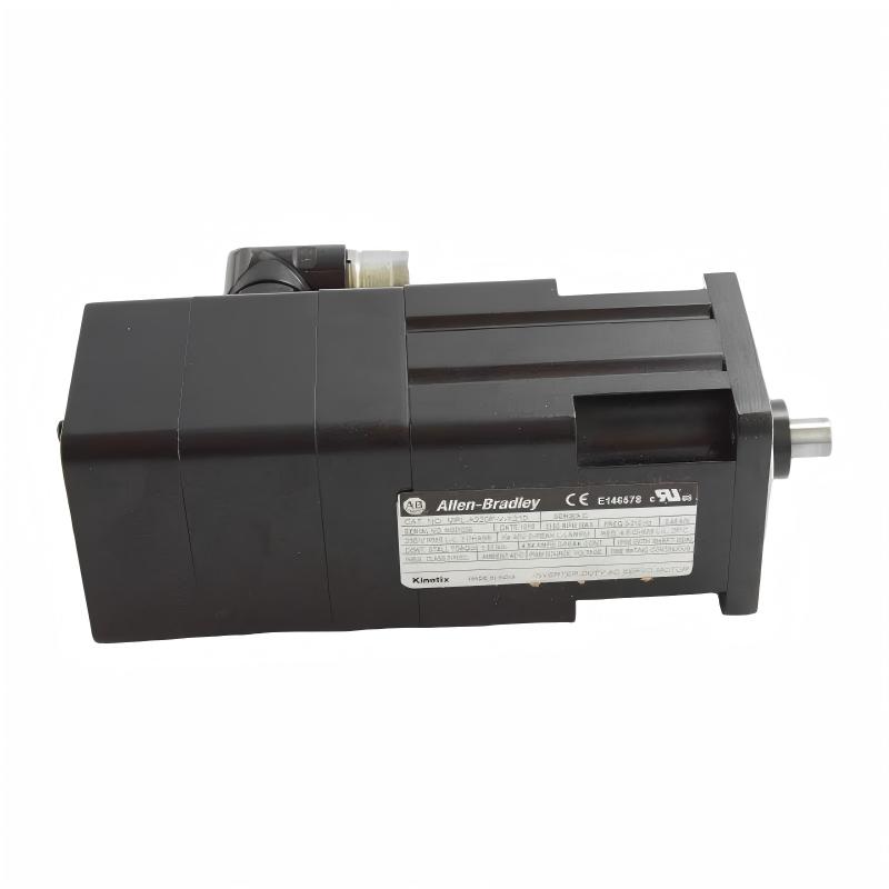
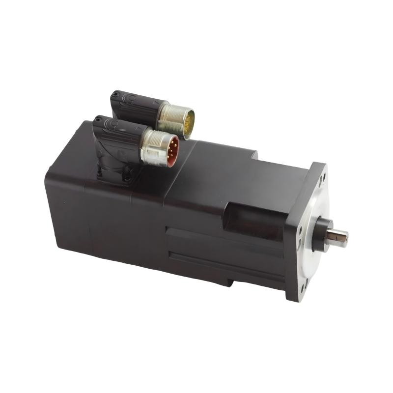
- Allen Bradley
- MPL-A220F-V-X209
- Servo Motor
- USA
- 40 mm
- 1.92 kg
- Xiamen, China
- New & In Stock
- T/T, PayPal, Western Union
- 1 Year
- 1-3 Working Days
- DHL, UPS, TNT, FedEx and EMS.
- 24-Hour Service
- COO
- 2
Our advantage

Global Logistics
We have a 10-year logistics and express cooperation agreement, so our products can be shipped to any place in the world.

Brand new and original
Our products are imported in bulk from the place of origin. Because of the cooperative relationship, our products are all original and 100% new.

24-hour service
We provide 7*24 hours service to our customers. We will be there whenever you need us.

Price advantage
All our products are priced very favorably because we have our own warehouse and supply.
| Company Information | |||
| [email protected] | |||
| Mobile | +8615980777398 | ||
| +8615980777398 | |||
| 15980777398 |
Product Overview
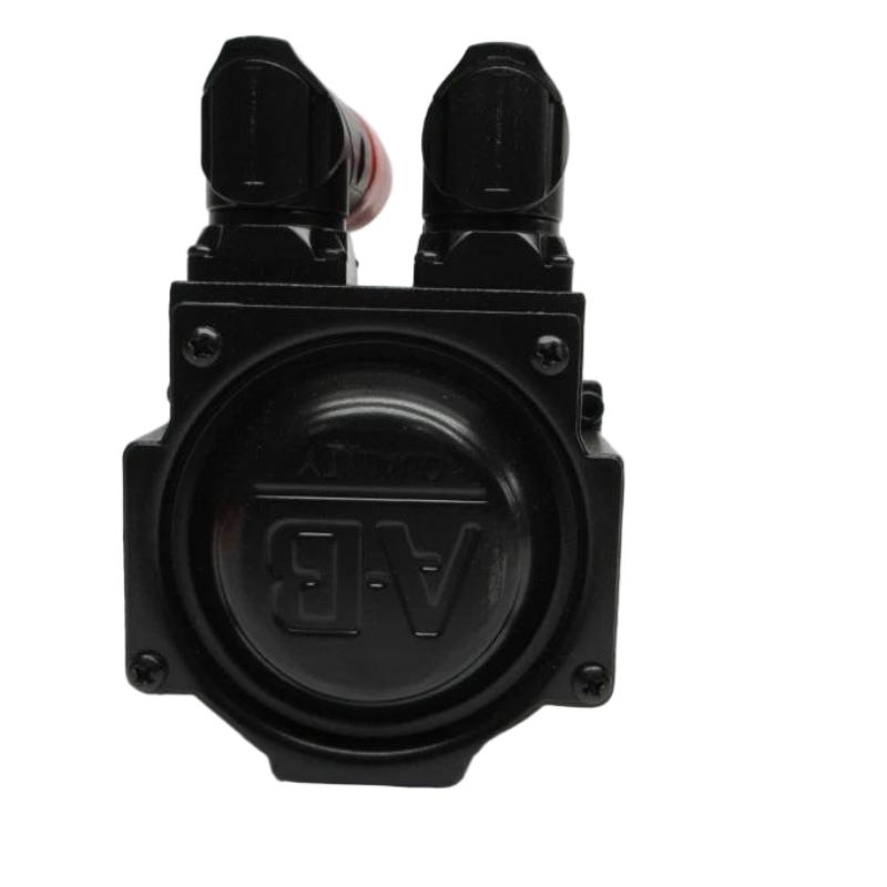
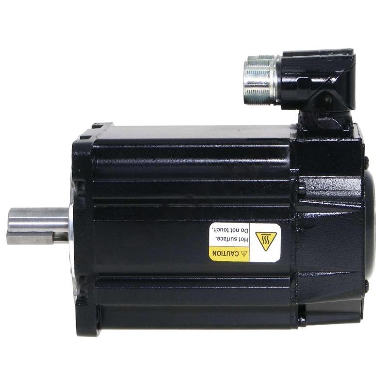
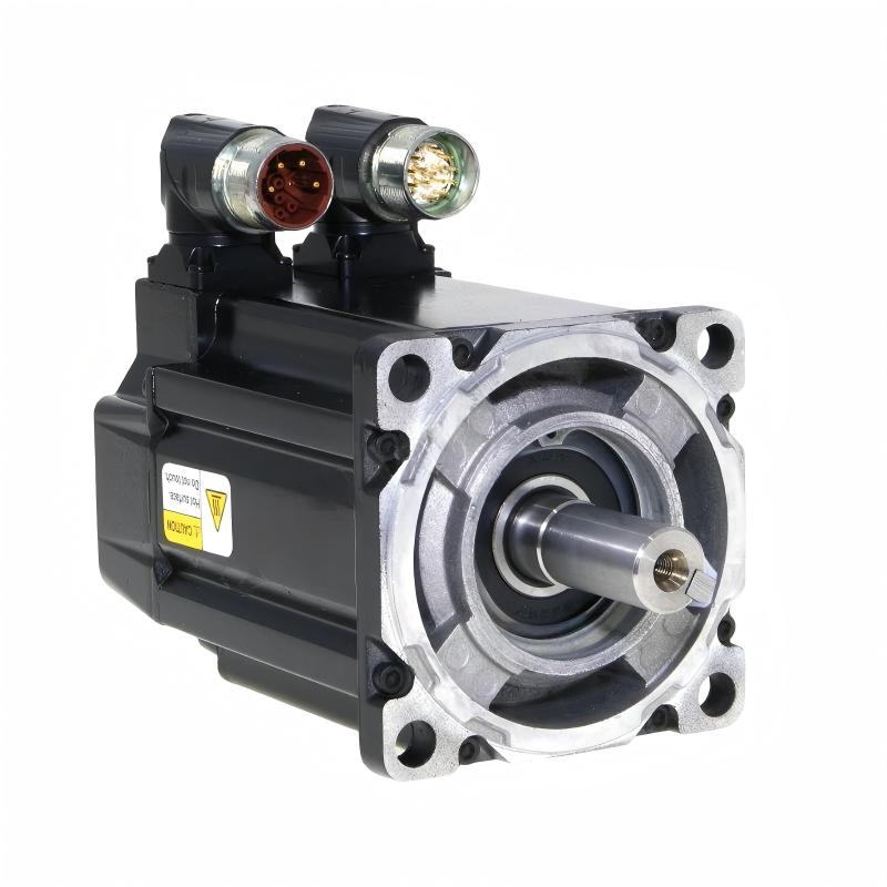
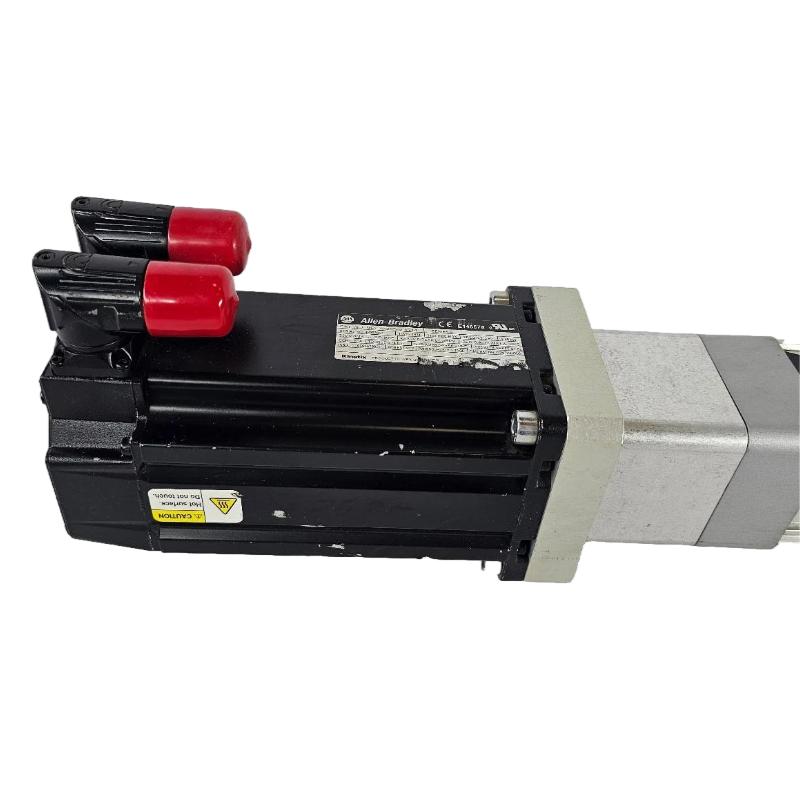
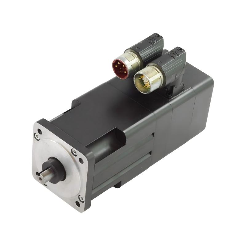
The Allen Bradley MPL-A220F-V-X209 Servo Motor is an industrial AC servo motor designed for use in precision motion-control systems. As part of the Allen Bradley MPL Series of low-inertia servo motors, the MPL-A220F-V-X209 is intended for applications where controlled acceleration, repeatable positioning, coordinated motion, and reliable machine operation are important.
With a 40 mm frame size and a listed weight of 1.92 kg, the MPL-A220F-V-X209 provides a compact motor solution for machine builders working with limited installation space. Its compact mechanical format makes it suitable for integration into automated machinery where the motor must provide controlled rotary motion without adding unnecessary mechanical bulk.
Servo motors such as the MPL-A220F-V-X209 are typically integrated with a compatible servo drive, motion controller, feedback system, mechanical transmission, and machine-control software. The complete motion system allows the controller to command motor speed, position, acceleration, and deceleration according to the requirements of the machine.
The MPL-A220F-V-X209 can therefore be considered as one component within a complete Allen Bradley motion-control architecture rather than as a standalone motor. Correct drive matching, feedback compatibility, mechanical installation, and application configuration are important for achieving reliable operation.
Technical Specifications
| Parameter | Specification |
|---|---|
| Manufacturer | Allen Bradley |
| Product Family | MPL Series |
| Model | MPL-A220F-V-X209 |
| Product Type | AC Servo Motor |
| Motor Technology | Permanent-Magnet Servo Motor |
| Frame Size | 40 mm |
| Weight | 1.92 kg |
| Application | Industrial Motion Control |
| Primary Function | Precision rotary motion |
| Control System | Compatible Servo Drive and Motion Controller |
| Installation | Machine-mounted |
| Typical Applications | Automation Machinery, Positioning Systems, Packaging, Material Handling, Motion-Control Equipment |
Note: The frame size and weight above are based on the supplied product information. Exact electrical ratings, feedback configuration, connector arrangement, shaft configuration, rated torque, rated speed, voltage, and other performance characteristics should be confirmed against the specific motor nameplate and applicable technical documentation before engineering or replacement.
What Is the Allen Bradley MPL-A220F-V-X209?
The MPL-A220F-V-X209 is an Allen Bradley servo motor designed to convert electrical control commands into controlled mechanical rotation.
Unlike a conventional motor that may simply operate at a commanded speed, a servo motor is normally used as part of a feedback-based motion system. The servo drive controls the motor while feedback information allows the control system to monitor the motor’s actual operating condition.
A simplified servo system can be represented as:
Motion Controller → Servo Drive → MPL-A220F-V-X209 Motor → Mechanical Load
with feedback information returning through the motor’s feedback system to the drive and controller.
This closed-loop architecture allows automated machinery to perform controlled movements such as positioning, indexing, synchronization, acceleration, deceleration, and repeated machine cycles.
The compact 40 mm frame size makes the MPL-A220F-V-X209 suitable for machine designs where cabinet and mechanical installation space must be used efficiently.
Servo Motor Working Principle
The MPL-A220F-V-X209 operates as part of a coordinated servo-control system.
The motion controller first determines the required movement based on the machine program. This command may represent a target position, speed, acceleration profile, or coordinated movement.
The servo drive receives the command and supplies controlled electrical power to the motor. The motor converts this electrical energy into rotary mechanical motion.
Feedback from the motor is used by the control system to compare commanded motion with actual motor behavior. The drive can then continuously adjust motor operation to reduce the difference between the commanded and actual motion.
The basic control sequence can be summarized as:
Command → Servo Drive → Motor Rotation → Feedback → Correction
This closed-loop approach is particularly useful for automated machinery requiring repeatable motion.
Main Functions of the MPL-A220F-V-X209
Precision Motion
The servo motor is designed for controlled rotary motion within an appropriate servo-control architecture. This makes it suitable for machinery where positioning and repeatability are important.
Controlled Acceleration and Deceleration
Servo systems can apply programmed acceleration and deceleration profiles. This allows machine designers to control how quickly mechanical components reach the required operating speed.
Position Control
When paired with a compatible feedback and control system, the motor can participate in precise positioning operations.
Speed Regulation
The servo drive can regulate motor speed according to the motion command and feedback information.
Coordinated Motion
Multiple servo motors can be coordinated by a suitable motion controller for applications involving synchronized machine axes.
Compact Machine Integration
The 40 mm frame size provides a compact mechanical form factor for applications where installation space is limited.
Role in an Allen Bradley Motion-Control System
The MPL-A220F-V-X209 should normally be viewed as one part of a larger automation architecture.
A typical motion-control system may include:
- PLC or motion controller
- Servo drive
- MPL Series servo motor
- Motor feedback system
- Power wiring
- Feedback wiring
- Machine mechanics
- Gearbox or coupling
- Linear actuator or rotary mechanism
- HMI
- Industrial communication network
- Safety system
The controller determines the required machine movement while the servo drive manages electrical power delivered to the motor.
The motor produces the required mechanical rotation, while feedback allows the system to monitor actual motor behavior.
This division of responsibilities enables the complete automation system to perform repeatable and coordinated machine movements.
Industrial Applications
The Allen Bradley MPL-A220F-V-X209 can be considered for a variety of industrial motion-control applications when its electrical and mechanical characteristics are correctly matched to the machine.
Packaging Machinery
Servo motors are frequently used in packaging equipment for controlled indexing, product positioning, cutting, feeding, and coordinated movement.
Material Handling
Automated conveyors, positioning mechanisms, transfer systems, and other material-handling equipment can use servo motors where controlled motion is required.
Assembly Machines
Automated assembly equipment can use servo-controlled axes to position components accurately during repetitive production operations.
Machine Tools
Servo motors can be incorporated into machine-tool axes and auxiliary mechanisms requiring controlled movement.
Labeling and Printing Equipment
Applications requiring coordinated material movement can benefit from servo-based speed and position control.
Pick-and-Place Equipment
Servo-controlled axes can provide repeatable movement for automated picking and placement operations.
Automated Production Lines
The motor can form part of a larger multi-axis automation system in which several motors operate under coordinated control.
Mechanical Integration
Correct mechanical installation is important for servo motor performance and service life.
The 40 mm frame size should be considered when designing the motor mounting arrangement and determining the available machine space.
Important mechanical considerations include:
- Motor mounting orientation
- Shaft alignment
- Coupling selection
- Load characteristics
- Radial loading
- Axial loading
- Mechanical resonance
- Vibration
- Thermal conditions
- Cable routing
- Service access
The motor shaft should be correctly aligned with the driven equipment. Misalignment can introduce unwanted mechanical forces and vibration.
Flexible couplings may be used where appropriate, but the coupling must be compatible with the motor shaft and the driven mechanism.
The exact shaft dimensions, mounting-hole arrangement, allowable shaft loading, and mechanical interface should be confirmed from the specific motor documentation before installation.
Servo Drive Integration
A servo motor should be matched carefully with its compatible servo drive.
The drive must be capable of providing the electrical characteristics required by the motor and supporting the appropriate feedback arrangement.
During system design, engineers should verify:
- Motor model
- Drive compatibility
- Feedback compatibility
- Power requirements
- Motor cable
- Feedback cable
- Connector configuration
- Motion-control platform
- Application load
- Required acceleration
- Required speed
- Required torque
- Safety requirements
A motor should not be connected to an arbitrary drive simply because the physical connector appears compatible.
Correct drive and motor pairing is essential for stable servo operation.
Installation Guidelines
1. Verify the Motor Identification
Before installation, confirm the complete model number:
MPL-A220F-V-X209
Check the motor nameplate and compare the identification with the engineering documentation.
2. Inspect the Motor
Before mounting, inspect the motor for:
- Physical damage
- Bent or damaged shaft
- Damaged connectors
- Cable damage
- Contamination
- Corrosion
- Loose mounting hardware
Do not install a motor with visible mechanical or electrical damage until it has been properly evaluated.
3. Install the Motor Securely
The motor should be mounted using the appropriate machine mounting arrangement.
The mounting surface should be rigid and properly aligned.
4. Check Shaft Alignment
Incorrect alignment can create excessive mechanical loading and vibration.
Verify alignment between the servo motor shaft and the driven machine before commissioning.
5. Connect Motor Wiring
Use the appropriate motor cable and connector arrangement for the actual motor and drive combination.
Power wiring should be installed according to the applicable electrical requirements.
6. Connect Feedback
The feedback connection is an important part of the servo system.
A damaged or incorrectly connected feedback cable can prevent the drive from operating correctly or cause feedback-related faults.
7. Check Grounding
Proper grounding and bonding should be implemented according to the applicable machine and drive installation requirements.
8. Verify the Mechanical Load
Confirm that the connected load does not exceed the mechanical capabilities of the motor and transmission system.
Commissioning the MPL-A220F-V-X209
Commissioning should be performed systematically rather than immediately operating the motor at full machine speed.
Step 1: Verify Motor Identification
Confirm that the installed motor matches the configured motor information.
Step 2: Verify Drive Configuration
The servo drive should be configured for the correct motor and feedback arrangement.
Step 3: Check Wiring
Inspect motor power, feedback, grounding, and communication connections.
Step 4: Check Mechanical Movement
Before full-speed operation, verify that the machine mechanism can move freely and safely.
Step 5: Perform Low-Speed Testing
Initial movement should normally be performed at a controlled speed.
Observe:
- Motor rotation
- Direction
- Vibration
- Noise
- Drive status
- Feedback behavior
- Machine movement
Step 6: Verify Positioning
Where the application uses position control, confirm that commanded and actual movement correspond correctly.
Step 7: Increase Operating Conditions Gradually
After basic operation has been verified, the machine can be tested progressively under normal operating conditions.
Troubleshooting the MPL-A220F-V-X209
Servo motor problems should be diagnosed as part of the complete motion-control system.
Motor Does Not Rotate
Possible areas to inspect include:
- Servo drive status
- Drive enable signal
- Motor power connection
- Feedback connection
- Control command
- Safety circuit
- Motor configuration
- Drive fault condition
- Mechanical obstruction
The motor itself should not automatically be assumed to be defective.
Servo Drive Reports a Feedback Fault
Check:
- Feedback cable
- Feedback connector
- Connector seating
- Cable damage
- Drive configuration
- Motor identification
- Feedback-related diagnostics
A feedback fault may originate from the wiring or drive rather than the motor.
Motor Vibrates
Potential causes include:
- Mechanical misalignment
- Incorrect tuning
- Excessive mechanical resonance
- Unbalanced load
- Coupling problems
- Incorrect control configuration
- Feedback-related issues
Mechanical and control-system conditions should both be investigated.
Motor Overheats
Possible contributing factors include:
- Excessive load
- Inadequate cooling
- High-duty-cycle operation
- Mechanical resistance
- Incorrect application configuration
- Environmental temperature
The actual operating load should be compared with the motor’s applicable specifications.
Positioning Is Inaccurate
Check:
- Feedback system
- Mechanical backlash
- Coupling condition
- Machine rigidity
- Servo tuning
- Load characteristics
- Motion-controller configuration
Positioning accuracy is determined by the complete mechanical and control system, not by the motor alone.
Maintenance Recommendations
Although servo motors are designed for industrial service, preventive inspection can help identify developing problems.
Mechanical Inspection
Check mounting hardware and mechanical connections periodically.
Shaft and Coupling Inspection
Inspect the motor shaft and coupling for signs of abnormal wear, misalignment, or vibration.
Cable Inspection
Check motor and feedback cables for:
- Cuts
- Abrasion
- Crushing
- Excessive bending
- Loose connectors
- Connector damage
Environmental Inspection
Keep the motor installation environment within the applicable operating conditions.
Avoid unnecessary exposure to:
- Excessive moisture
- Dust
- Contamination
- Excessive heat
- Strong vibration
Performance Monitoring
Unexpected changes in:
- Motor noise
- Vibration
- Temperature
- Positioning behavior
- Acceleration
- Deceleration
may indicate a developing mechanical, electrical, or control-system issue.
Replacement Considerations
When replacing an Allen Bradley servo motor, the complete model number should be verified rather than selecting a motor based only on frame size.
For the MPL-A220F-V-X209, important identification information includes:
- Manufacturer
- Product family
- Complete catalog number
- Frame size
- Motor mounting arrangement
- Shaft configuration
- Feedback configuration
- Connector arrangement
- Compatible servo drive
- Machine application
The supplied physical information is:
Frame Size: 40 mm
Weight: 1.92 kg
The frame size is useful for mechanical planning, but it does not by itself establish electrical or control-system compatibility.
Physical Dimensions and Weight
The Allen Bradley MPL-A220F-V-X209 has a listed 40 mm frame size and a weight of 1.92 kg.
| Physical Parameter | Value |
|---|---|
| Frame Size | 40 mm |
| Weight | 1.92 kg |
The weight can be useful when planning motor handling, machine-axis design, shipping, and equipment layout.
For detailed mechanical installation, engineers should additionally verify the exact motor outline drawing, mounting dimensions, shaft dimensions, connector position, and allowable shaft loading for the specific configuration.
Compatible System Architecture
The MPL-A220F-V-X209 can be incorporated into an industrial motion system consisting of several layers.
Control Layer
A PLC or motion controller generates machine movement commands.
Drive Layer
The servo drive converts control commands into controlled electrical power for the motor.
Motor Layer
The MPL-A220F-V-X209 converts electrical energy into mechanical rotation.
Feedback Layer
Motor feedback provides information used by the servo-control system to monitor actual motor behavior.
Mechanical Layer
The motor drives the machine mechanism through a coupling, gearbox, belt, screw, or other suitable transmission arrangement.
Operator Layer
An HMI or supervisory system can provide machine status, operating commands, alarms, and diagnostic information.
This architecture allows the servo motor to become part of a complete automated production system.
Engineering Best Practices
Several practices can improve the reliability of a servo motor installation.
Select the Motor According to the Application
Motor selection should consider load inertia, required speed, torque, acceleration, duty cycle, and mechanical transmission characteristics.
Match the Drive Carefully
The servo drive should be compatible with the exact motor configuration.
Minimize Mechanical Misalignment
Correct shaft alignment and suitable coupling selection are important for reducing mechanical stress.
Separate Power and Feedback Wiring
Where applicable, appropriate cable routing can reduce the possibility of electrical interference affecting sensitive feedback signals.
Verify Motion Before Full Production
Initial commissioning should be performed under controlled conditions before the machine is placed into continuous production.
Maintain Accurate Identification
Keep the complete motor model number in maintenance records so that future replacement work can be performed accurately.
Key Advantages
- Compact 40 mm frame size
- Listed weight of 1.92 kg
- Suitable for industrial servo motion-control applications
- Designed for integration with compatible servo-drive systems
- Supports controlled rotary machine movement
- Suitable for positioning and coordinated automation applications
- Compact form factor for machine integration
- Applicable to packaging, assembly, material handling, and automated machinery
- Can form part of a complete Allen Bradley motion-control architecture
Technical FAQs
What is the Allen Bradley MPL-A220F-V-X209?
The MPL-A220F-V-X209 is an Allen Bradley MPL Series servo motor designed for industrial motion-control applications.
What is the frame size of the MPL-A220F-V-X209?
The listed frame size is 40 mm.
How much does the MPL-A220F-V-X209 weigh?
The listed motor weight is 1.92 kg.
What is the main function of this servo motor?
Its primary function is to convert controlled electrical power into mechanical rotary motion within a servo-control system.
Can the MPL-A220F-V-X209 operate by itself?
A servo motor is normally used with a compatible servo drive and motion-control system. Proper feedback and drive configuration are also important for closed-loop servo operation.
What applications can use the MPL-A220F-V-X209?
Potential applications include automated machinery, packaging equipment, assembly systems, material handling, positioning mechanisms, and other industrial motion-control equipment, provided the motor is correctly matched to the application.
What should be checked before replacing this motor?
The complete catalog number, frame size, mechanical interface, shaft configuration, feedback arrangement, drive compatibility, and application requirements should be checked.
Can another 40 mm servo motor directly replace the MPL-A220F-V-X209?
Not necessarily. Frame size alone does not establish compatibility. Electrical characteristics, feedback, mounting, shaft configuration, drive compatibility, and application requirements must also be verified.
What causes servo motor vibration?
Possible causes include mechanical misalignment, coupling problems, load imbalance, resonance, tuning issues, or feedback/control problems. The complete motion system should be inspected.
Why is feedback important in a servo system?
Feedback provides information about actual motor behavior, allowing the servo drive and controller to regulate motion more accurately.
Conclusion
The Allen Bradley MPL-A220F-V-X209 Servo Motor is a compact industrial motion-control motor intended for integration into precision automated machinery. With a listed 40 mm frame size and 1.92 kg weight, it provides a compact mechanical solution for applications where controlled rotary movement and efficient machine integration are important.
The motor should be evaluated as part of a complete servo system that includes a compatible drive, motion controller, feedback arrangement, wiring, and mechanical load. Proper motor-drive matching, mechanical alignment, feedback integrity, and commissioning procedures are essential for reliable operation.
For replacement and maintenance work, the complete MPL-A220F-V-X209 catalog number should always be verified. The supplied 40 mm frame size and 1.92 kg weight are useful identification and mechanical-planning parameters, while exact electrical and mechanical characteristics should be confirmed from the specific motor configuration before installation.