

ProductPRODUCT
Featured products
Contact Us
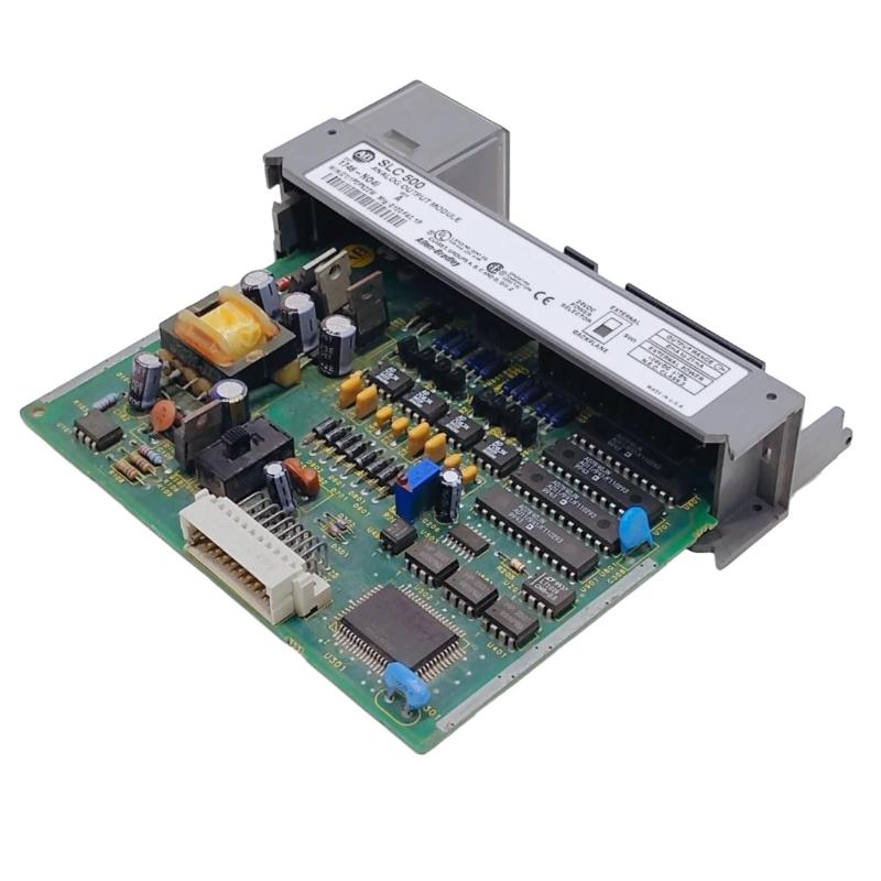
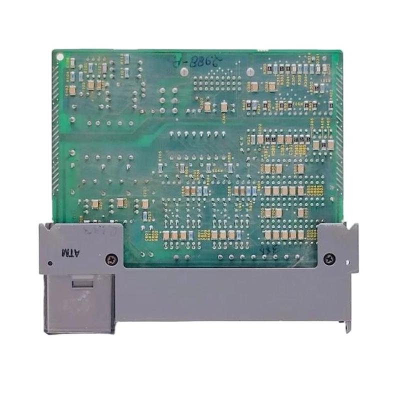
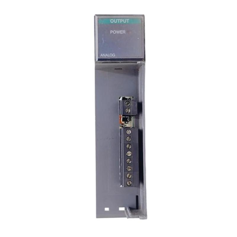
- Allen Bradley
- 1746-NO4IK
- Analog Output Module
- USA
- 145 × 32 × 140 mm
- 0.2kg
- Xiamen, China
- New & In Stock
- T/T, PayPal, Western Union
- 1 Year
- 1-3 Working Days
- DHL, UPS, TNT, FedEx and EMS.
- 24-Hour Service
- COO
- 3
Our advantage

Global Logistics
We have a 10-year logistics and express cooperation agreement, so our products can be shipped to any place in the world.

Brand new and original
Our products are imported in bulk from the place of origin. Because of the cooperative relationship, our products are all original and 100% new.

24-hour service
We provide 7*24 hours service to our customers. We will be there whenever you need us.

Price advantage
All our products are priced very favorably because we have our own warehouse and supply.
| Company Information | |||
| [email protected] | |||
| Mobile | +8615980777398 | ||
| +8615980777398 | |||
| 15980777398 |
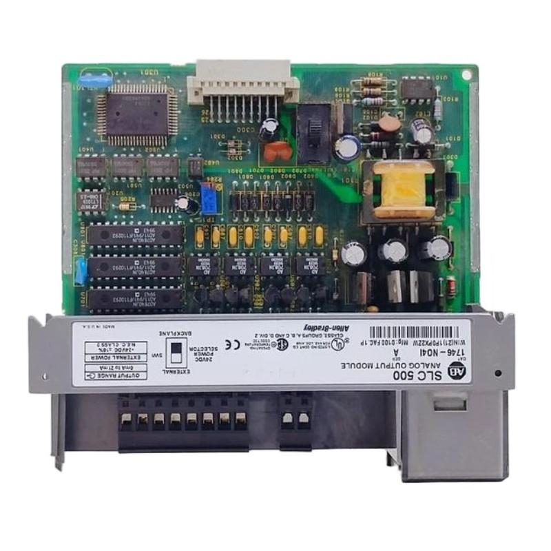
Allen-Bradley 1746-NO4I Product Overview and Technical Guide
1. Product Introduction
The Allen-Bradley 1746-NO4I is an analog output module in the SLC 500 programmable controller family. It is designed to convert digital output values generated by a programmable logic controller (PLC) into analog current signals that can be used by compatible industrial equipment.
In a typical automation system, the PLC executes control logic based on sensor readings, operator commands, and programmed operating conditions. The 1746-NO4I provides an interface between that digital control logic and field devices that require an analog current reference.
Examples include compatible control valves, variable-speed drive references, current-operated actuators, and other industrial devices that accept analog current inputs.
Unlike a digital output module, which generally switches an output between discrete states, an analog output module can provide a continuously adjustable signal within its supported operating range. This allows the controller to regulate a process variable rather than simply turn a device on or off.
The 1746-NO4I is particularly relevant to existing installations built around the SLC 500 platform. In these systems, the module can provide the analog output capability required by the original machine design without changing the basic control architecture.
2. Product Identification and Main Parameters
| Parameter | Specification |
|---|---|
| Model | 1746-NO4I |
| Brand | Allen-Bradley |
| Product category | Analog output module |
| Product series | SLC 500 |
| Module type | PLC analog current output module |
| Number of outputs | 4 |
| Output signal | Analog current |
| Output range | 0–20 mA |
| Output isolation | Verify the exact electrical isolation specification for the module revision |
| Controller platform | Compatible SLC 500 chassis and processors |
| Installation method | Installed in a compatible SLC 500 chassis |
| Power arrangement | Powered through the compatible chassis backplane |
| Field wiring | Connected through the applicable module wiring interface |
| Typical applications | Process control, actuator reference signals, and industrial current-loop interfaces |
| Display | No independent operator display |
| Dimensions (H × W × D) | Approximate dimensions require confirmation against the exact module drawing |
| Weight (kg) | Exact module weight requires confirmation against the specific hardware revision |
| Product lifecycle | Legacy / discontinued product |
| Replacement considerations | Verify chassis compatibility, output range, wiring, configuration, and control-system requirements |
Technical note: The 1746-NO4I is the current-output version of the four-channel analog output module family. Do not confuse it with voltage-output variants, which provide different signal types. Exact dimensions and weight should be verified from the physical unit or its mechanical drawing before using them for shipping calculations, cabinet design, or spare-parts documentation.
3. Detailed Technical Specifications
The 1746-NO4I is designed to generate four independent analog current outputs. Each channel converts a numerical value in the PLC output data table into a corresponding current signal.
The output signal can be used as a reference by compatible field equipment, provided that the equipment’s input range and electrical requirements match the module’s specifications.
| Parameter | Technical specification |
|---|---|
| Model | 1746-NO4I |
| Module family | SLC 500 |
| Number of output channels | 4 |
| Output signal type | Current |
| Normal output range | 0–20 mA |
| Maximum full-scale output | 21 mA |
| Digital-to-analog converter resolution | 14 bit |
| Nominal output resolution | Approximately 2.56348 µA per least significant bit |
| Maximum specified load resistance | 500 Ω |
| Maximum load reactance | 100 µH |
| Step response | Approximately 2.5 ms to 95% |
| Non-linearity | 0.05% |
| Maximum overall accuracy at 25°C | ±0.298% of full scale |
| Maximum overall accuracy from 0–60°C | ±0.541% of full scale |
| Field wiring to backplane isolation | 500 V DC continuous, according to the applicable module specification |
| Backplane current draw at 5 V DC | Approximately 55 mA |
| Backplane current draw at 24 V DC | Approximately 195 mA |
| External supply option | 24 V DC; verify supply arrangement and installation requirements |
| Recommended cable | Shielded instrumentation cable, selected according to the installation |
| Maximum wire size | 14 AWG, subject to terminal requirements |
| Operating temperature | 0–60°C |
| Storage temperature | −40–85°C |
| Relative humidity | 5–95%, non-condensing |
| Calibration | Factory calibrated; follow the applicable maintenance procedure |
| Approximate module dimensions (H × W × D) | Approximately 145 × 32 × 140 mm; verify against the hardware drawing |
| Approximate module weight | 0.20 kg |
| Product status | Discontinued / legacy |
The specifications above describe the module’s key operating characteristics. Actual performance in a control system depends on the wiring, power supply, connected load, temperature, controller configuration, and condition of the hardware.
Understanding the 0–20 mA output range
The module’s normal output range is 0–20 mA. The controller writes a digital value, and the module converts that value into a current signal.
For a simple linear scaling example:
| Digital command as a percentage of range | Expected output current |
|---|---|
| 0% | 0 mA |
| 25% | 5 mA |
| 50% | 10 mA |
| 75% | 15 mA |
| 100% | 20 mA |
These values illustrate linear scaling. The actual PLC counts and engineering-unit conversion must be configured correctly in the application.
The module also has a specified overrange capability of approximately 5%, allowing the output to reach close to 21 mA. Overrange capability should not be confused with the normal operating range of a connected device.
Load resistance and output performance
The connected device’s input resistance affects the voltage required to drive the current loop. The 1746-NO4I is specified for loads up to 500 Ω under its stated operating conditions.
Before connecting a valve positioner, drive, or other current-operated device, check its input impedance and wiring arrangement. A load that exceeds the supported range can prevent the module from producing the intended current.
Isolation and electrical installation
The module provides field-wiring-to-backplane isolation as specified for this product family. Isolation helps separate the field circuit from the controller backplane, but it should not be interpreted as proof that every output channel is individually isolated from every other channel.
Use suitable wiring, grounding, shielding, and protection practices. Disconnect power and follow the plant’s electrical safety procedures before installing or removing the module.
4. Product Applications

4.1 Control valves and actuators
A current output can provide a reference signal to a compatible valve positioner or actuator controller. The PLC can adjust the signal according to process conditions, allowing the valve to regulate the flow of a liquid or gas.
For example, a controller may calculate the required valve position from a flow measurement and send the corresponding current command through one of the module’s output channels.

4.2 Motor and drive reference signals
Compatible motor drives can accept analog current references for speed or process control. The PLC can adjust the output according to production requirements, operator settings, or feedback from sensors.
The module supplies the reference signal; the drive remains responsible for controlling the motor according to its own configuration and protection functions.

4.3 Water treatment and pumping systems
A compatible control system can use analog outputs to adjust pump references, regulate flow, or command associated process equipment.
The PLC can calculate the required output from tank level, pressure, or flow measurements. Proper scaling and feedback configuration are essential to prevent unstable or inaccurate process control.

4.4 Process control systems
In process applications, the module can generate current references for compatible control equipment. The output may represent a setpoint, valve command, drive reference, or another variable defined by the application.
The ability to use four channels makes the module useful when several independent analog commands are needed within one SLC 500 system.

4.5 Packaging and manufacturing machinery
Packaging lines and production machines may use analog references to control speed, tension, positioning equipment, or other compatible devices.
The 1746-NO4I can provide these signals when the machine’s design requires current outputs and the connected equipment supports the module’s electrical characteristics.
Other possible applications
The module may also be used in compatible material-handling equipment, mixing systems, industrial ovens, auxiliary process skids, and older OEM machinery.
Its suitability depends on the required output signal, the load connected to each channel, the controller’s capabilities, and the environmental conditions of the installation.
5. Product Advantages
5.1 Four analog output channels in one module
The module provides four current outputs within a single SLC 500 module. This allows multiple compatible devices to receive analog commands without requiring a separate module for every output.
For a machine with several adjustable process variables, this can simplify the control-system layout and help make better use of available chassis slots.
5.2 Fine output resolution
The 14-bit digital-to-analog conversion provides a defined range of output steps across the current range. This supports relatively fine adjustment of analog commands compared with simple on/off control.
The effective accuracy of a complete system still depends on the module’s specified error limits, load characteristics, field-device accuracy, and correct scaling.
5.3 Fast response for many control tasks
The specified step response is approximately 2.5 ms to 95%. This provides a relatively quick response to a change in the commanded output under the stated conditions.
Actual system response may be slower because of PLC scan time, application filtering, network communication, actuator mechanics, and process dynamics.
5.4 Supports standard industrial current signals
The 0–20 mA output range is used in a variety of industrial control applications. It can be suitable for devices specifically designed to accept this signal range.
The output range should always be checked against the connected device. A device that requires a different range, such as 4–20 mA, may require a different configuration or a different module.
5.5 Fits into an established SLC 500 architecture
For existing systems, the 1746-NO4I can provide the analog output capability expected by the original program and wiring design.
Keeping a compatible module can reduce the scope of an immediate maintenance repair compared with replacing the controller platform and modifying the entire application.
5.6 Provides defined load and accuracy characteristics
The published load range, resolution, response, and accuracy specifications help engineers determine whether the module is suitable for a particular control task.
These values can be used when assessing connected equipment, setting control-system tolerances, and troubleshooting output performance.
5.7 Useful for maintaining legacy equipment
The module remains relevant to maintenance teams supporting machinery designed around the SLC 500 family.
A verified spare can be valuable when an existing analog output channel is critical to production. Since the product is discontinued, however, long-term spare-parts planning should include condition checks and an eventual modernization strategy.
6. Limitations and Selection Considerations
Although the 1746-NO4I provides useful analog output capabilities, several details must be considered before selecting or replacing it.
Current range. The module’s normal output range is 0–20 mA. It should not automatically be treated as a direct replacement for a 4–20 mA-only output requirement without confirming the system’s scaling and connected-device requirements.
Load resistance. The connected load must fall within the supported electrical range. Wiring resistance and the input characteristics of the receiving device should be considered.
Channel isolation. Do not assume that all four channels are individually isolated. Check the exact module documentation and wiring design.
Power requirements. Verify the chassis and power-supply capacity, including the module’s backplane current requirements and any external supply requirements.
Legacy platform. The SLC 500 family is an older platform. Availability of new modules and support options may be limited, so spare-parts planning is important.
Replacement compatibility. A similar catalog number may indicate a voltage-output module or a combined analog input/output module. Match the signal type, number of channels, wiring interface, and configuration before ordering.
Safety and commissioning. Analog outputs may affect the operation of valves, drives, and other machinery. Validate output scaling, limits, interlocks, and behavior during faults before returning the equipment to production.
7. Brand and Product Series
| Parameter | Description |
|---|---|
| Brand | Allen-Bradley |
| Product series | SLC 500 |
| Product category | Programmable controller I/O |
| Module type | Analog current output |
| Catalog number | 1746-NO4I |
| Output channels | 4 |
| Output range | 0–20 mA |
| Installation | Compatible SLC 500 chassis |
| Main purpose | Converting PLC digital values into analog current commands |
| Product lifecycle | Discontinued / legacy |
About the brand
Allen-Bradley is an industrial automation brand associated with programmable controllers, I/O modules, operator interfaces, motor control, and industrial networking products.
Its control products are often used together in machine-control and process-control systems. In a typical installation, the controller executes the logic, I/O modules connect the controller to field devices, and the operator interface provides a means for personnel to monitor and operate the equipment.
About the SLC 500 series
SLC 500 is a family of programmable controller systems that includes processors, chassis, power supplies, digital I/O modules, and analog I/O modules.
The 1746-NO4I belongs to the 1746 I/O module family. It is designed to operate within a compatible chassis rather than as a standalone device.
When replacing this module, check the existing processor, chassis, slot arrangement, output wiring, and program configuration. A replacement from a newer controller family may require hardware changes, program conversion, and commissioning work.
8. Five Related Models in the Same Series
The following models are related to the 1746-NO4I by their SLC 500 family or analog I/O function. The dimensions and weights are approximate planning figures where stated; verify the mechanical drawing and catalog data for the actual hardware revision.
| Model | Product type | Main parameters | Approximate dimensions (H × W × D) | Weight (kg) | Typical use |
|---|---|---|---|---|---|
| 1746-NO4V | Analog output module | 4 voltage outputs; compatible signal range must be verified | Approx. 145 × 32 × 140 mm | Approx. 0.20 | Provides analog voltage references |
| 1746-NO8I | Analog output module | 8 current outputs; confirm exact output range and power requirements | Verify exact module drawing | Verify exact revision | Multiple current commands in a compatible SLC 500 system |
| 1746-NO8V | Analog output module | 8 voltage outputs; confirm output range and load requirements | Verify exact module drawing | Verify exact revision | Multiple voltage-reference signals |
| 1746-NIO4I | Combined analog I/O module | 2 analog inputs and 2 analog current outputs | Approx. 145 × 32 × 140 mm | Approx. 0.20 | Systems needing both analog feedback and current commands |
| 1746-NI4 | Analog input module | 4 analog input channels; voltage/current capabilities depend on the module and configuration | Approx. 145 × 32 × 140 mm | Approx. 0.20 | Reading analog measurements from compatible sensors and transmitters |
How to choose among these models:
– Choose the 1746-NO4V when the field equipment requires a voltage output rather than a current output.
– Consider the 1746-NO8I when a compatible system requires more current output channels, after confirming power and configuration requirements.
– Consider the 1746-NO8V when multiple voltage-output channels are needed.
– Consider the 1746-NIO4I when the application needs both analog input feedback and analog current outputs.
– Consider the 1746-NI4 when the primary requirement is to measure analog signals rather than generate output commands.
These models have different electrical functions. A module with the same number of channels is not necessarily an appropriate replacement unless its signal type, scaling, wiring, and system compatibility match the application.
9. Five Other Popular Models from the Same Brand
The following products represent other common types of industrial automation hardware. They are not direct replacements for the 1746-NO4I, but they may be relevant when maintaining, expanding, or modernizing a control system.
| Model | Product category | Main parameters | Approximate dimensions | Weight (kg) | Typical application |
|---|---|---|---|---|---|
| 1746-NI4 | SLC 500 analog input module | 4 analog input channels; configured for compatible voltage/current signals | Approx. 145 × 32 × 140 mm | Approx. 0.20 | Analog measurement and process feedback |
| 1746-NIO4I | SLC 500 combined analog I/O | 2 analog inputs and 2 analog current outputs | Approx. 145 × 32 × 140 mm | Approx. 0.20 | Combined measurement and control |
| 1746-IB16 | SLC 500 digital input module | 16 DC digital input points; confirm voltage compatibility | Approx. 145 × 32 × 140 mm | Approx. 0.20 | Reading switches, sensors, and discrete status signals |
| 1746-OB16 | SLC 500 digital output module | 16 DC digital output points; verify load and output-current limits | Approx. 145 × 32 × 140 mm | Approx. 0.20 | Switching compatible discrete field devices |
| 1746-P2 | SLC 500 power supply | Chassis power supply; verify chassis compatibility and load capacity | Verify exact power-supply drawing | Verify exact revision | Supplying the compatible SLC 500 chassis |
The dimensions and weights above are indicative rather than a substitute for the relevant mechanical drawings. Different module types and revisions can vary, and power supplies generally have a different physical form from I/O modules.
These products illustrate how the 1746-NO4I may fit into a broader SLC 500 system:
-
Analog input modules measure process signals.
-
Analog output modules generate adjustable references.
-
Digital input modules monitor discrete conditions.
-
Digital output modules command compatible discrete loads.
-
Power supplies provide the electrical power required by the chassis and installed modules.
10. Installation and Configuration Considerations
10.1 Confirm chassis compatibility
Before installation, verify that the chassis and controller support the module. Check the available slot, power budget, and installation instructions for the particular SLC 500 configuration.
10.2 Confirm the field wiring
Review the existing wiring diagram and terminal assignments before disconnecting the original module. Identify the connected devices and confirm whether the output circuit uses a current input designed for the 0–20 mA range.
10.3 Check output scaling
The PLC program must translate engineering values into the appropriate output counts. Incorrect scaling can cause a valve, drive, or other device to receive a command that is higher or lower than intended.
For example, if a process value is intended to represent 0–100% output, the program must map the minimum and maximum engineering values to the corresponding output range correctly.
10.4 Test the output under controlled conditions
After installation, test each channel independently. Confirm that the commanded output corresponds to the measured current and that the connected equipment responds as expected.
Where practical, test with the field device disconnected or isolated according to the approved commissioning procedure. Do not perform tests that could cause an unsafe movement, process upset, or unexpected machine operation.
10.5 Document the final configuration
Record the module catalog number, hardware revision, wiring arrangement, scaling parameters, and test results. This information helps reduce troubleshooting time during future maintenance.
11. Maintenance and Troubleshooting
| Symptom | Possible cause | Recommended check |
|---|---|---|
| Output current remains at zero | Incorrect configuration, wiring fault, missing supply, or module failure | Check output data, power requirements, and field wiring |
| Output current is lower than expected | Excessive load resistance, wiring resistance, scaling error, or damaged circuit | Measure the current and verify the connected load |
| Output current does not track the command | PLC logic, incorrect data mapping, or module fault | Compare commanded values with measured output |
| One channel behaves differently from the others | Channel wiring, connected load, or channel-specific fault | Test the affected channel using an approved procedure |
| Connected actuator responds erratically | Incorrect scaling, unstable control logic, electrical interference, or actuator problem | Check the signal, shielding, grounding, and control-loop tuning |
| Replacement module fails to operate | Incorrect module type, chassis incompatibility, or wiring/configuration mismatch | Recheck the catalog number, slot compatibility, and configuration |
A systematic diagnostic approach is preferable to replacing components immediately. A fault that appears to originate in an analog output module may instead be caused by field wiring, the receiving device, the PLC program, or an incorrect engineering-unit conversion.
12. Overall Product Assessment
The Allen-Bradley 1746-NO4I is a four-channel analog current output module in the SLC 500 family. It converts digital control values into 0–20 mA signals for compatible industrial devices, making it suitable for applications that require adjustable process commands rather than simple discrete switching.
Its main strengths are four current-output channels in one module, 14-bit conversion resolution, a defined output response, and compatibility with established SLC 500 installations.
Its main limitations are its legacy product status, the need for a compatible chassis, and the importance of matching output signal range and load requirements to the connected equipment.
For an existing installation, the 1746-NO4I remains relevant when the original control architecture is still in use and a matching replacement is required. For a new or modernized system, it is worth comparing the cost of maintaining the legacy platform with the engineering effort needed to migrate the control system to a currently supported architecture.
Final recommendation: Before purchasing a replacement, confirm the full catalog number, output range, module revision, chassis compatibility, wiring, load resistance, and power requirements. For a change to a different analog module, verify that the new hardware can meet the application’s electrical and functional requirements rather than relying on physical similarity alone.