
NewsNEWCENTER
Featured products
Contact Us
Allen-Bradley 1734-IT2I Thermocouple Input Module Installation Guide
2026-11-18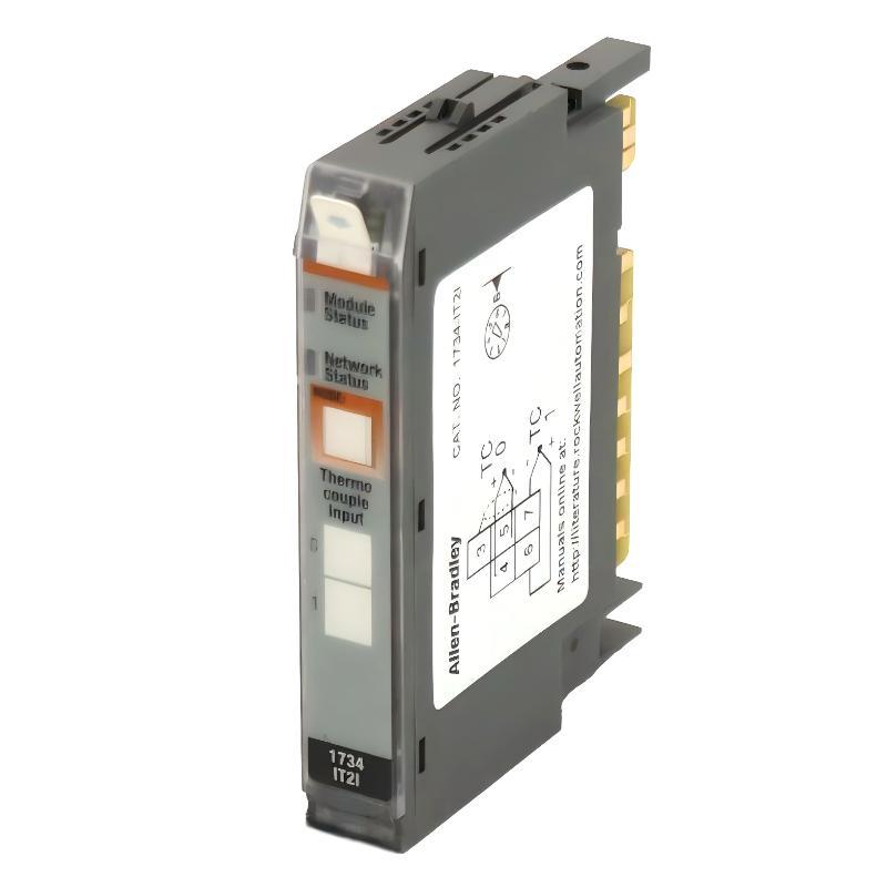
The Allen-Bradley 1734-IT2I installation requires correct thermocouple polarity, cold-junction compensation, input channel configuration, and POINTBus integration. This two-channel POINT I/O thermocouple input module is designed to measure low-level millivolt signals generated by industrial temperature sensors and convert them into temperature data for a PLC control system. It supports multiple thermocouple types, including B, C, E, J, K, N, R, S, and T.
Unlike a conventional voltage input module, the 1734-IT2I must be configured according to the actual thermocouple type and measurement range. Incorrect sensor selection, reversed thermocouple wiring, or unsuitable cold-junction compensation can produce inaccurate temperature readings even when the module is communicating normally with the controller.
Allen-Bradley 1734-IT2I POINT I/O Module Architecture
The 1734-IT2I is part of the Allen-Bradley POINT I/O 1734 distributed I/O family. It provides two differential thermocouple input channels with input-to-system isolation. Each channel measures a low-level thermoelectric signal and uses configured sensor characteristics to calculate the corresponding temperature.
How the 1734-IT2I Measures Temperature
A thermocouple produces a small voltage based on the temperature difference between its measuring junction and reference junction. The 1734-IT2I receives this millivolt signal, applies the configured thermocouple linearization, and calculates the temperature value.
Cold-junction compensation is essential because the measured thermocouple voltage represents a temperature difference rather than an absolute temperature. The module therefore needs a suitable reference temperature measurement at the thermocouple connection point.
The 1734-IT2I works with the appropriate cold-junction terminal base assembly. The installation must follow the selected terminal assembly and thermocouple wiring requirements.
Allen-Bradley 1734-IT2I Technical Specifications
| Parameter | Specification |
|---|---|
| Manufacturer | Allen-Bradley / Rockwell Automation |
| Model | 1734-IT2I |
| Product family | POINT I/O 1734 |
| Module type | Thermocouple Input Module |
| Number of channels | 2 differential inputs |
| Input configuration | Isolated millivolt inputs |
| Default input range | -70 to +70 mV |
| Supported sensor types | B, C, E, J, K, N, R, S, T |
| Resolution | 15 bits plus sign |
| POINTBus current | 175 mA at 5 VDC |
| Maximum power dissipation | 1.0 W |
| Maximum thermal dissipation | 3.3 BTU/hr |
| Isolation voltage | 50 V continuous, I/O to system |
| External DC supply | Not required for the module itself |
| Approximate dimensions | 56 × 12 × 75.5 mm |
| Approximate weight | 0.036 kg |
| Operating temperature | -20 to 55 °C |
| Mounting | POINT I/O mounting base |
Planning an Allen-Bradley 1734-IT2I Installation
Before installing the module, examine the existing POINT I/O station and determine which terminal base assembly is required. The 1734-IT2I uses a compatible cold-junction terminal base, commonly identified as the 1734-TBCJC configuration. Confirm the exact terminal base catalog number and revision against the module’s installation documentation.
Installation Preparation Checklist
- Verify the complete module catalog number: 1734-IT2I.
- Confirm the POINT I/O adapter and available POINTBus capacity.
- Check that the mounting base is compatible with the thermocouple module.
- Identify the thermocouple type used on each channel.
- Check thermocouple extension wire material and polarity.
- Confirm the cold-junction compensation arrangement.
- Review the PLC hardware configuration and available I/O addresses.
- Prepare suitable shielded thermocouple cable.
- Check the cabinet grounding and electromagnetic interference protection.
The module draws up to 175 mA from the 5 VDC POINTBus. The adapter and power distribution arrangement must have sufficient capacity for the complete I/O station, including other connected modules.
Allen-Bradley 1734-IT2I DIN Rail Mounting and Terminal Base Installation
Mechanical installation should be completed before connecting the thermocouple conductors. A secure mounting arrangement prevents intermittent electrical contact and makes future maintenance easier.
Mounting Base Positioning
Install the compatible terminal base on the POINT I/O DIN rail assembly according to the manufacturer’s mounting instructions. Confirm that the base is correctly aligned with the adjacent I/O modules and that the POINTBus connections are properly engaged.
For the 1734-IT2I, use the specified cold-junction terminal base assembly. Do not substitute a standard terminal base without verifying compatibility.
Installing the 1734-IT2I Module
- Place the module in the correct position above the mounting base.
- Align the module contacts with the terminal base connections.
- Press the module into position until the locking mechanism engages.
- Inspect the module-to-base connection.
- Confirm that the terminal assembly is mechanically secure.
- Check the module keying arrangement before completing the installation.
Do not force the module into the terminal base. Misalignment can damage the electrical contacts or the mechanical locking mechanism.
1734-IT2I Thermocouple Wiring and Polarity Configuration
Thermocouple wiring requires more attention than ordinary discrete input wiring because the generated signal is extremely small. Incorrect extension wire, reversed polarity, and poor terminal connections can introduce measurement errors.
Identifying the Thermocouple Type
Before connecting the sensors, determine whether the application uses Type K, J, T, E, N, R, S, B, or C thermocouples. The configured sensor type must match the physical sensor and extension wire.
For example, connecting a Type K thermocouple while configuring the channel for Type J produces an incorrect temperature conversion. The module may still return a plausible numerical value, making the error difficult to detect without an independent temperature reference.
Thermocouple Polarity
Every thermocouple has positive and negative conductors. Their identification depends on the thermocouple type and applicable wire color standard.
- Identify the positive and negative conductors from the sensor documentation.
- Use compatible thermocouple extension wire.
- Maintain polarity throughout the complete field wiring route.
- Avoid unnecessary junctions between dissimilar conductor materials.
- Keep thermocouple cables away from high-current motor and drive wiring.
- Use suitable shielding and grounding arrangements.
Do not rely exclusively on wire colors because industrial wiring standards can differ between regions and suppliers.
Channel Assignment
The module provides two independent input channels. Establish a clear relationship between the physical sensor, terminal connections, and PLC channel assignment.
| Input Channel | Example Application | PLC Tag Example |
|---|---|---|
| Channel 0 | Reactor temperature measurement | Reactor_Temperature |
| Channel 1 | Outlet temperature measurement | Outlet_Temperature |
These are example assignments. Actual terminal numbers and wiring connections must be taken from the correct terminal base wiring diagram.
Allen-Bradley 1734-IT2I Cold-Junction Compensation Setup
Cold-junction compensation is one of the most important configuration considerations for the 1734-IT2I. A thermocouple measures the temperature difference between its measuring junction and reference junction. Without correct compensation, the displayed process temperature can be significantly different from the actual temperature.
Why Cold-Junction Compensation Matters
Consider a Type K thermocouple measuring a process temperature of 250 °C. The voltage produced by the sensor depends on both the hot-junction temperature and the temperature at the reference connection.
If the reference temperature is incorrectly measured or compensated, the PLC may report an offset even when the thermocouple itself is operating correctly.
Terminal Base and Reference Temperature
Use the appropriate cold-junction terminal base assembly and follow the manufacturer’s installation instructions. The terminal base arrangement provides the reference temperature information needed by the thermocouple measurement system.
During commissioning, inspect the terminal base installation, terminal condition, and surrounding cabinet temperature. Avoid placing heat-generating components immediately next to the thermocouple connection area when this can be prevented by cabinet design.
1734-IT2I Studio 5000 Setup and System Configuration
After completing the physical installation, configure the module in the applicable Rockwell Automation engineering environment. The controller configuration must match the installed module type, channel assignments, and thermocouple sensor characteristics.
Module Recognition and Hardware Configuration
- Open the applicable Logix project.
- Locate the POINT I/O adapter in the I/O configuration tree.
- Add or verify the 1734-IT2I module at its physical station position.
- Confirm that the module identity matches the installed hardware.
- Open the module configuration properties.
- Set the appropriate input type for Channel 0.
- Set the appropriate input type for Channel 1.
- Configure the required data format and filter settings.
- Review alarm and fault handling options.
- Download or apply the configuration according to the approved change procedure.
Thermocouple Input Type Selection
The module supports several thermocouple types. Each channel should be configured independently according to the connected sensor.
| Thermocouple Type | Temperature Range (°C) |
|---|---|
| Type B | 300 to 1800 |
| Type C | 0 to 2315 |
| Type E | -250 to 1000 |
| Type J | -210 to 1200 |
| Type K | -250 to 1372 |
| Type N | -250 to 1300 |
| Type R | 0 to 1768 |
| Type S | 0 to 1768 |
| Type T | -250 to 400 |
The listed ranges are sensor-type ranges. The usable measurement range of a complete installation must also account for the sensor, wiring, terminal base, and application requirements.
Allen-Bradley 1734-IT2I Input Filtering and Temperature Data Scaling
Thermocouple signals are sensitive to electrical noise. The 1734-IT2I provides configurable input filtering to help stabilize measurements in industrial environments.
Input Filter Selection
A filter setting that is too aggressive can delay the response to a genuine process temperature change. A setting that is too fast may allow electrical interference to produce unstable readings.
For slow thermal processes such as tanks, ovens, and heating vessels, a moderate filtering arrangement may be appropriate. Faster thermal applications require a careful balance between measurement stability and response time.
Temperature Data Handling
The module provides input data and channel status information to the controller. The PLC program should distinguish between a valid temperature measurement and an input fault condition.
Do not use an input value for closed-loop temperature control without first checking the associated channel status and configured fault behavior.
Allen-Bradley 1734-IT2I Installation Commissioning and Signal Validation
Commissioning should verify the entire measurement chain rather than checking only whether the module appears online.
Electrical and Configuration Verification
- Confirm the module is recognized by the controller.
- Check the module and network status indicators.
- Verify the input channel indicators.
- Confirm both thermocouple types are correctly configured.
- Check sensor polarity and terminal connections.
- Verify cold-junction compensation.
- Check for channel underrange and overrange conditions.
- Compare the PLC temperature value with an independent reference.
Temperature Comparison Test
For a commissioning example, assume a Type K thermocouple is installed in a temperature-controlled vessel operating near 150 °C.
The engineer checks the temperature using an independent calibrated reference instrument. If the reference reads 149.5 °C and the PLC reports 150.2 °C, the difference is 0.7 °C.
This result should be evaluated against the complete measurement system’s accuracy requirements rather than automatically attributed to the input module.
1734-IT2I Installation Case: Temperature Readings Differ Between Channels
Illustrative engineering scenario: A POINT I/O station monitors two heating zones using separate Type K thermocouples connected to the 1734-IT2I.
During commissioning, Channel 0 displays a stable temperature close to the independent reference instrument. Channel 1, however, consistently reports a higher temperature.
The technician initially suspects that the second thermocouple may be defective. Instead of replacing the sensor immediately, the engineer follows the measurement path.
- Verify the Type K configuration on both channels.
- Inspect the polarity of Channel 1.
- Check the thermocouple extension cable.
- Inspect the cold-junction terminal arrangement.
- Compare the channel reading with an independent reference.
- Check whether the error changes with cabinet temperature.
In this illustrative case, the discrepancy is traced to an incorrect extension wire connection near the terminal assembly. After correcting the wiring, the two measurements become consistent with their respective reference instruments.
The engineering lesson is that temperature measurement errors should be investigated through sensor compatibility, wiring, reference compensation, and software configuration before replacing the input module.
Allen-Bradley 1734-IT2I Installation Technical FAQs
What is the Allen-Bradley 1734-IT2I used for?
It is a two-channel POINT I/O thermocouple input module used to measure industrial temperatures and transfer the converted temperature data to a PLC control system.
How many thermocouples can the 1734-IT2I connect?
It supports two differential thermocouple input channels, allowing two independent temperature measurements.
Which thermocouple types are supported?
The supported types are B, C, E, J, K, N, R, S, and T.
Does the 1734-IT2I support millivolt inputs?
Yes. It has two isolated millivolt input channels with a default input range of approximately -70 to +70 mV. Thermocouple operation requires the appropriate sensor configuration and linearization.
Does the module require an external 24 VDC power supply?
The module itself does not require a separate external DC supply. It receives its module operating power through the POINTBus. The complete POINT I/O station still requires an appropriate system power arrangement.
Which terminal base should be used with the 1734-IT2I?
Use the compatible cold-junction terminal base assembly specified for the module, commonly the 1734-TBCJC arrangement. Verify the exact catalog number and revision before installation.
Why is cold-junction compensation necessary?
A thermocouple measures a temperature difference between two junctions. Cold-junction compensation accounts for the reference junction temperature so the controller can calculate the correct measuring-junction temperature.
Can Channel 0 and Channel 1 use different thermocouple types?
Yes. The channels can be configured independently, allowing different supported thermocouple types to be used when the application and wiring arrangement permit.
What causes unstable temperature readings?
Potential causes include electromagnetic interference, loose terminals, incorrect shielding, incompatible extension wire, grounding problems, and unsuitable input filter settings.
How can the accuracy of the 1734-IT2I be checked?
Compare the configured channel measurement with an independent calibrated temperature reference under stable operating conditions. Consider sensor accuracy, extension wire, cold-junction compensation, and installation effects.
Allen-Bradley 1734-IT2I Installation Conclusion and Overall Technical Assessment
The Allen-Bradley 1734-IT2I POINT I/O Thermocouple Input Module provides two differential measurement channels for industrial temperature monitoring. Its support for nine thermocouple types, configurable input filtering, and integration with the POINT I/O architecture make it suitable for distributed temperature acquisition in process automation and machine control systems.
Reliable installation depends on correct terminal base selection, thermocouple polarity, sensor type configuration, cold-junction compensation, and POINTBus capacity planning. These factors should be checked before the module is placed into normal production service.
For engineers working with Allen-Bradley PLC systems, a systematic Installation Guide and commissioning process helps improve temperature measurement consistency, reduce false alarms, and establish dependable temperature data for monitoring, interlocking, and process control applications.