
NewsNEWCENTER
Featured products
Contact Us
Allen Bradley 1606-XLDNET8 DC Power Module Installation Guide
2026-08-27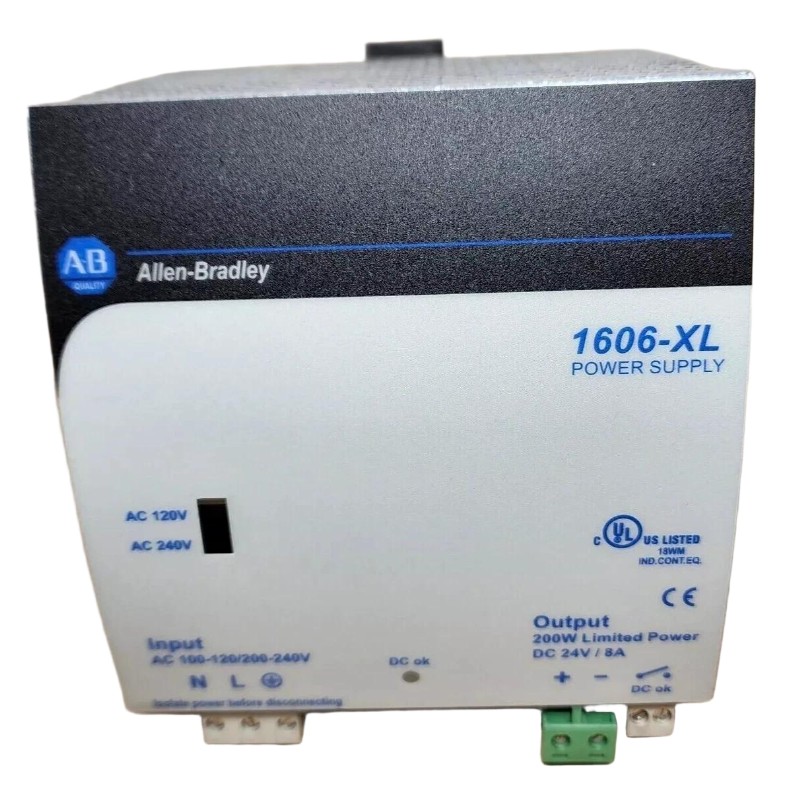
Table of Contents
- Allen Bradley 1606-XLDNET8 DC Power Module Installation Overview
- Allen Bradley 1606-XLDNET8 DC Power Module Application
- Allen Bradley 1606-XLDNET8 Installation Planning and Load Review
- Allen Bradley 1606-XLDNET8 Mounting and Cabinet Arrangement
- Allen Bradley 1606-XLDNET8 DC Power Module Wiring
- Allen Bradley 1606-XLDNET8 Setup and Pre-Energization Checks
- Allen Bradley 1606-XLDNET8 Commissioning with PLC Systems
- Allen Bradley 1606-XLDNET8 Output and Load Validation
- Allen Bradley 1606-XLDNET8 Field Installation Example
- Allen Bradley 1606-XLDNET8 Installation FAQ
- Allen Bradley 1606-XLDNET8 Overall Technical Summary
Allen Bradley 1606-XLDNET8 DC Power Module Installation Overview
Allen Bradley 1606-XLDNET8 installation should be approached as a complete DC power-distribution task rather than simply mounting a power module and applying voltage. Correct source identification, polarity, protection, conductor selection, load calculation, and downstream verification are essential for reliable industrial automation operation.
The 1606-XLDNET8 is identified as a DC power module within the Allen Bradley 1606 family. In an automation cabinet, a DC power module can form part of the electrical path supplying PLC Controllers, I/O Modules, Sensors, communication equipment, relays, and other control loads.
The most important commissioning principle is simple: verify the power path at the module and again at the actual load. A normal measurement at the power module does not automatically prove that a remote PLC or I/O device is receiving stable voltage.
Allen Bradley 1606-XLDNET8 DC Power Module Application
The Allen Bradley 1606-XLDNET8 is used within industrial control-power arrangements where a controlled DC supply is required for automation equipment. Its role should be evaluated in relation to the upstream source and the total downstream load.
Typical control-panel applications may include PLC Controller systems, distributed I/O, instrumentation, machine-control circuits, and auxiliary DC-powered devices. The actual loads must be confirmed from the project electrical drawings rather than assumed from the module’s presence in the cabinet.
Allen Bradley 1606-XLDNET8 DC Power Module System Role
- Provides DC power within an industrial automation cabinet.
- Supports selected control and instrumentation circuits.
- Can supply PLC Controller and I/O-related loads where correctly configured.
- Forms part of the cabinet’s DC power-distribution architecture.
- Provides a defined power source for connected automation equipment.
Allen Bradley 1606-XLDNET8 Installation Planning and Load Review
Before Installation, identify every device that will be connected to the 1606-XLDNET8 output. Do not calculate the load using only the PLC Controller. Communication interfaces, I/O Modules, Sensors, relays, indicator devices, and other auxiliary equipment may contribute to the actual current demand.
Pay particular attention to equipment that switches on after the machine starts. A power circuit can appear completely stable during an idle commissioning test and become unstable when additional field devices are energized.
Allen Bradley 1606-XLDNET8 Pre-Installation Checks
- Confirm the exact module identification.
- Verify the intended DC source.
- Review the electrical schematic.
- Determine the expected connected load.
- Identify startup and intermittent loads.
- Check branch protection requirements.
- Review conductor sizing and expected voltage drop.
- Confirm cabinet ventilation and environmental conditions.
- Identify the critical PLC and I/O loads.
Keep the original load calculation with the commissioning documentation. If another technician adds equipment to the DC bus later, the original baseline provides an immediate reference for determining whether the System Configuration has changed.
Allen Bradley 1606-XLDNET8 Mounting and Cabinet Arrangement
The 1606-XLDNET8 should be mounted in the designated control-panel location with sufficient clearance for wiring, inspection, and heat dissipation. The final cabinet arrangement should prevent nearby high-heat equipment from unnecessarily increasing the operating temperature of the DC power section.
Organize wiring so that the input and output circuits are easy to trace. Clear conductor identification is particularly valuable during Troubleshooting because it allows an engineer to follow the power path without disconnecting unrelated equipment.
Where the cabinet contains drives, contactors, motors, or other switching equipment, maintain appropriate separation between power wiring and sensitive PLC communication or Sensor wiring according to the panel design requirements.
Allen Bradley 1606-XLDNET8 DC Power Module Wiring
Allen Bradley 1606-XLDNET8 wiring must be performed according to the actual terminal markings and approved electrical documentation. Before connection, isolate the relevant power source using the site’s electrical safety procedure.
DC polarity must be verified before energization. Do not assume that conductor colors are correct, particularly in an existing cabinet that has undergone previous modifications.
Allen Bradley 1606-XLDNET8 Wiring Inspection
- Verify the incoming DC source.
- Confirm positive and negative polarity.
- Check protective devices.
- Verify conductor size.
- Inspect terminal tightness.
- Confirm the intended downstream circuit.
- Separate sensitive signal wiring from noisy power circuits where appropriate.
- Label the DC distribution branches clearly.
After termination, perform a point-to-point inspection against the electrical drawing. This simple check can identify reversed polarity, incorrect branch connections, or a wire landed on the wrong terminal before those errors become equipment faults.
Allen Bradley 1606-XLDNET8 Setup and Pre-Energization Checks
The Allen Bradley 1606-XLDNET8 Setup should establish a known electrical baseline before the complete machine is placed into automatic operation. If the commissioning procedure permits staged energization, begin with the power circuit and then introduce the downstream loads progressively.
1606-XLDNET8 SETUP CHECK

DC SOURCE
    |
    |-- Verify source voltage
    |-- Verify polarity
    |-- Check protection
    |
    v
1606-XLDNET8
    |
    |-- Energize under approved conditions
    |-- Measure DC output
    |
    v
DISTRIBUTION
    |
    |-- Connect control loads
    |-- Monitor voltage
    |
    v
PLC / I/O / SENSOR
    |
    |-- Verify stable operation
If the initial DC measurement is abnormal, stop the sequence and investigate the source and wiring. Do not continue connecting downstream equipment simply to determine whether the problem disappears.
Allen Bradley 1606-XLDNET8 Commissioning with PLC Systems
Commissioning should verify both electrical performance and automation behavior. Once the 1606-XLDNET8 is energized, check the PLC Controller, I/O Modules, communication devices, and relevant Sensors under realistic operating conditions.
A useful field method is to measure the DC voltage at three points: the power module output, the main distribution point, and the most electrically distant critical load. This creates a simple voltage-drop profile for the installation.
Allen Bradley 1606-XLDNET8 Commissioning Data
- DC input voltage.
- DC output voltage at the module.
- Voltage at the main distribution point.
- Voltage at critical downstream equipment.
- PLC Controller operating status.
- I/O Module status.
- Communication status.
- Sensor signal stability.
Record measurements under both idle and normal operating load. A commissioning value taken with the machine stopped may not represent the actual voltage available when contactors, valves, interfaces, or other loads become active.
Allen Bradley 1606-XLDNET8 Output and Load Validation
Output validation should not be limited to a no-load voltage check. The downstream DC circuit should be observed while representative equipment is operating.
For example, if the DC voltage is stable at the 1606-XLDNET8 but drops noticeably at a remote I/O station when multiple loads switch on, the problem may be associated with cable resistance, terminal quality, or excessive branch loading rather than the power module itself.
Allen Bradley 1606-XLDNET8 Installation Acceptance Checks
- Input power is correctly connected.
- DC polarity is confirmed.
- Output voltage is stable.
- Distribution wiring is correctly terminated.
- Critical PLC equipment remains stable.
- I/O Modules operate normally.
- Communication devices remain online.
- Sensors operate without unexplained power-related fluctuations.
Allen Bradley 1606-XLDNET8 Field Installation Example
In one commissioning case, a new DC power module was installed to support a PLC Controller and several remote control devices. Initial testing was successful because the PLC started normally and the local DC voltage appeared stable.
The engineer then enabled the machine’s auxiliary circuits. At that point, one remote I/O section intermittently dropped offline. Instead of replacing the power module, the engineer compared the voltage at the module with the voltage at the remote I/O distribution point.
The module-side measurement remained stable, while the remote branch experienced a substantially larger voltage reduction during the load transition. The diagnostic focus therefore shifted from the DC power module to the distribution circuit.
A terminal connection in the remote branch was found to be inadequately secured. The increased current during the auxiliary load transition produced additional voltage drop across the connection.
After the connection was corrected, the remote I/O was tested repeatedly under the same operating sequence. The communication dropout did not return.
This case illustrates an important Installation and Commissioning principle: when a downstream automation device fails while the power module measurement remains stable, measure the voltage at the affected device before declaring the power module defective.
Allen Bradley 1606-XLDNET8 Installation FAQ
What is the Allen Bradley 1606-XLDNET8?
The Allen Bradley 1606-XLDNET8 is identified as a DC power module used within industrial automation power-distribution systems. Its actual application should be confirmed against the project electrical design and product documentation.
Why should the 1606-XLDNET8 load be calculated before installation?
The connected load determines the electrical demand placed on the DC power system. Counting only the PLC Controller can underestimate the real demand when I/O Modules, Sensors, communication devices, relays, and other loads share the same circuit.
Where should DC voltage be measured during Commissioning?
Measure at the power module and, when practical, at important downstream distribution and load points. Comparing these values helps identify voltage-drop problems that may not be visible at the module terminals.
Can a wiring problem look like a 1606-XLDNET8 hardware fault?
Yes. Incorrect polarity, loose terminals, excessive cable resistance, incorrect branch wiring, or an overloaded circuit can produce PLC, I/O, communication, or Sensor symptoms that initially appear to originate from the power module.
What should be documented after 1606-XLDNET8 Setup?
Record the DC input and output measurements, representative load condition, downstream voltage measurements, PLC and I/O status, and any relevant observations from the commissioning test. These records provide a useful baseline for future Troubleshooting and Fault Diagnosis.
Allen Bradley 1606-XLDNET8 Overall Technical Summary
The Allen Bradley 1606-XLDNET8 Installation Guide should be applied to the entire DC power path, from the incoming source through the power module and distribution wiring to the final PLC, Module, Sensor, and communication loads.
Reliable Setup and Commissioning depend on correct polarity, appropriate protection, suitable wiring, realistic load calculations, and measurements taken under actual operating conditions. Measuring only the power-module terminals can miss problems occurring farther downstream.
For future maintenance, the commissioning baseline should be retained with the cabinet documentation. When a PLC Controller or I/O Module later develops an intermittent power-related fault, comparison with those original measurements can make Troubleshooting and Fault Diagnosis faster and more accurate.