
NewsNEWCENTER
Featured products

Contact Us
Allen Bradley 1606-XLB120E Power Supply Troubleshooting Guide
2026-08-18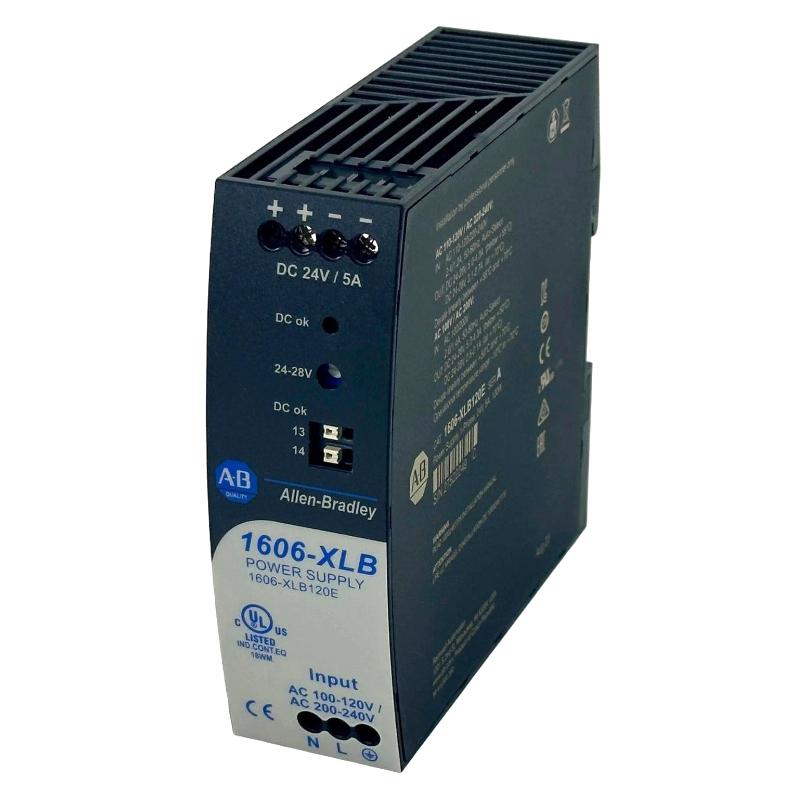
Table of Contents
- Allen Bradley 1606-XLB120E Power Supply Fault Diagnosis Approach
- Allen Bradley 1606-XLB120E Fault Symptoms
- Allen Bradley 1606-XLB120E Troubleshooting Evidence
- Common Allen Bradley 1606-XLB120E Fault Causes
- Allen Bradley 1606-XLB120E Voltage Drop Troubleshooting
- Allen Bradley 1606-XLB120E Load Isolation and Fault Diagnosis
- Allen Bradley 1606-XLB120E Real Troubleshooting Case
- Allen Bradley 1606-XLB120E Repair and Replacement Decision
- Allen Bradley 1606-XLB120E Recovery Verification
- Allen Bradley 1606-XLB120E Troubleshooting FAQ
- Allen Bradley 1606-XLB120E Overall Troubleshooting Summary
Allen Bradley 1606-XLB120E Power Supply Fault Diagnosis Approach
Allen Bradley 1606-XLB120E Troubleshooting should begin at the electrical source and move toward the failed equipment. If a PLC Controller suddenly restarts, a Module disappears from the network, or a Sensor becomes unstable, the power supply may be involved, but the symptom alone does not prove a 1606-XLB120E failure.
In field maintenance, the most reliable Fault Diagnosis method is to establish a reference measurement under normal operation and then determine what changes when the fault occurs. This prevents unnecessary replacement of good components and gives the engineer a defensible reason for each corrective action.
Allen Bradley 1606-XLB120E Fault Symptoms
A power-distribution fault can be surprisingly difficult to recognize because the automation system may generate secondary alarms instead of a direct power-supply alarm.
- PLC processor resets without an obvious program error.
- Remote I/O equipment repeatedly goes offline.
- Industrial communication nodes reconnect unexpectedly.
- Sensor readings fluctuate when motors or valves operate.
- Control relays chatter or release unexpectedly.
- DC voltage becomes lower as additional loads are enabled.
- Faults appear only after extended cabinet operation.
- The system recovers after a power cycle but the original cause remains.
Allen Bradley 1606-XLB120E Intermittent Power Faults
Intermittent faults should be treated as a separate diagnostic category. A power supply may measure correctly for several minutes while a loose connection, thermal condition, or switching event causes a short-duration disturbance later.
If possible, monitor the system while the production sequence that normally causes the fault is running. The objective is to capture the electrical condition at the exact time the PLC or Module changes state.
Allen Bradley 1606-XLB120E Troubleshooting Evidence
Good troubleshooting separates observations from assumptions. For example, “PLC reset occurred when valve bank started” is an observation. “The power supply is defective” is a conclusion that still requires evidence.
Allen Bradley 1606-XLB120E Diagnostic Measurement Points
- Incoming power source.
- 1606-XLB120E input terminals.
- 1606-XLB120E DC output terminals.
- Main DC distribution terminals.
- PLC Controller supply point.
- Remote I/O distribution point.
- Supply point of the device associated with the fault.
Normal condition:
  Vsource = measured reference
  Voutput = measured reference
  Vload   = measured reference

During fault:
  compare Vsource
  compare Voutput
  compare Vload

Interpretation:
  Voutput abnormal -> investigate supply/input/load
  Voutput normal + Vload abnormal -> investigate distribution
  all voltages normal -> investigate non-power-related causes
Common Allen Bradley 1606-XLB120E Fault Causes
The following fault patterns are particularly useful when investigating a control cabinet where the power supply is suspected.
- Overloaded DC circuit: additional devices may have been installed without updating the original load calculation.
- Shorted field device: a failed sensor, relay, or interface component can affect a common DC branch.
- Loose connection: mechanical resistance at a terminal can create a substantial voltage drop under load.
- Undersized distribution conductors: long cable paths can produce voltage loss that is not visible at the source.
- Input disturbance: unstable upstream power can affect the DC system.
- Thermal stress: cabinet temperature should be considered when the fault follows a time-dependent pattern.
- Switching disturbance: inductive equipment may create transient conditions on a shared control circuit.
Allen Bradley 1606-XLB120E Voltage Drop Troubleshooting
Voltage-drop analysis is one of the most effective ways to distinguish a supply problem from a distribution problem. Measure the voltage directly at the 1606-XLB120E and compare it with the voltage at the affected load while the fault condition is active.
For example, if the supply output remains at approximately 24.0 VDC while the PLC distribution point falls to 22.9 VDC during a load event, the investigation should focus on the wiring and connections between those points.
Do not dismiss a difference simply because the control system continues operating. A marginal DC voltage may not cause an immediate shutdown but can create intermittent communication faults, sensor instability, or repeated module resets.
Allen Bradley 1606-XLB120E Load Isolation and Fault Diagnosis
When the DC output changes significantly under load, isolate the downstream circuit according to the approved maintenance procedure. The purpose is to determine whether the abnormal condition follows a particular branch.
Suppose the 1606-XLB120E is stable with the PLC Controller connected but becomes unstable after a group of interface relays is energized. The relays should then become the next diagnostic boundary. If removing the branch restores stable voltage, investigate the branch wiring and devices before condemning the power supply.
Allen Bradley 1606-XLB120E Branch Fault Pattern
- Establish a normal voltage reference.
- Reproduce the original failure.
- Identify which load group was active when the fault appeared.
- Separate that load group from the DC bus when safe and permitted.
- Observe whether the supply returns to its previous condition.
- Test individual devices within the suspect branch.
- Correct the root cause and restore the System Configuration.
Allen Bradley 1606-XLB120E Real Troubleshooting Case
In one troubleshooting investigation, a control system experienced repeated PLC restarts during the transition from standby to automatic production. Initial maintenance measurements showed approximately 24 VDC at the power-supply terminals, and the 1606-XLB120E was suspected to be healthy.
The engineer then monitored the voltage while the automatic sequence was repeated. The PLC supply point briefly fell from approximately 24 VDC to around 22.7 VDC when several field loads were activated simultaneously. The event was not obvious during a simple static voltage measurement.
The next step was to identify which loads were switched at the same point in the sequence. A group of interface circuits was separated from the main PLC-related DC branch. The PLC remained stable when the group was isolated, which shifted the investigation away from the power supply and toward the affected branch.
Further inspection identified a high-resistance connection in the branch wiring. The resistance was not sufficient to produce an obvious fault during low-current operation, but the voltage drop increased when the load group was activated.
After corrective work, the same automatic production sequence was repeated multiple times. The PLC remained online and the original reset could no longer be reproduced.
The engineering lesson is important: when an automation system reports a power-related symptom, reproduce the event and follow the electrical path rather than replacing the first component that appears suspicious.
Allen Bradley 1606-XLB120E Repair and Replacement Decision
Repair should follow Fault Diagnosis, not precede it. If the 1606-XLB120E produces stable output with the downstream loads properly isolated and the abnormal condition is clearly located elsewhere, replacing the power supply is not justified.
If the input supply is verified, downstream shorts and overloads have been eliminated, wiring and terminals are sound, and the power supply itself continues to exhibit abnormal output behavior, replacement may be appropriate under the site’s maintenance procedure.
Allen Bradley 1606-XLB120E Safe Recovery Principles
- Never defeat a protective device merely to keep production running.
- Do not repeatedly energize a circuit with an unresolved short condition.
- Verify polarity before reconnecting sensitive PLC equipment.
- Inspect terminals following an overload or overheating event.
- Record measurements before and after corrective work.
- Test the system under representative operating conditions after recovery.
Allen Bradley 1606-XLB120E Recovery Verification
A successful restart is not sufficient evidence that the troubleshooting process is complete. The original failure condition should be reproduced as closely as possible after corrective work.
For example, if the original PLC reset occurred when multiple solenoid circuits were energized, those same circuits should be operated again while monitoring the DC bus. If the original fault occurred after several hours of operation, the repaired System Configuration should also be observed through a comparable operating period.
Allen Bradley 1606-XLB120E Post-Repair Checks
- Verify stable input power.
- Verify stable DC output at the supply.
- Verify voltage at critical downstream loads.
- Check PLC Controller status.
- Check I/O Module availability.
- Check communication stability.
- Operate switching loads under normal conditions.
- Document the final measurements and corrective action.
Allen Bradley 1606-XLB120E Troubleshooting FAQ
What should be measured when an Allen Bradley 1606-XLB120E fault is suspected?
Measure the incoming power, DC output at the 1606-XLB120E terminals, voltage at the main distribution point, and voltage at the affected PLC, Module, or field device. Comparing these measurements helps identify the fault location.
Can a 1606-XLB120E fault appear as a PLC communication problem?
Yes. A short-duration DC disturbance can cause a PLC Controller, remote I/O Module, or communication device to reset. The resulting alarm may look like a network problem even though unstable power is the initiating condition.
Why does the power supply work normally when the machine is stopped?
The fault may depend on load current, switching activity, or cabinet temperature. Static measurements during a stopped-machine condition may not reproduce the electrical stress present during automatic production.
Should the power supply be replaced after one unexplained PLC reset?
No. One reset is insufficient evidence. Establish whether the event corresponds with an input disturbance, DC voltage drop, switching event, loose connection, overload, or downstream device fault before deciding on replacement.
How can field engineers make 1606-XLB120E Troubleshooting more efficient?
Record normal measurements first, reproduce the fault, divide the power path into diagnostic boundaries, isolate suspect branches, and verify the repair using the same operating condition that originally produced the failure.
Allen Bradley 1606-XLB120E Overall Troubleshooting Summary
Allen Bradley 1606-XLB120E Troubleshooting is most effective when the engineer treats the power supply, distribution wiring, and connected automation equipment as one electrical system. A PLC Controller reset, I/O Module dropout, or unstable Sensor signal may originate anywhere along that path.
Reliable Fault Diagnosis requires measured evidence: compare the input and DC output, examine voltage at the actual load, reproduce intermittent events, isolate branches, and determine whether the abnormal condition follows the power supply or another part of the system.
Once the root cause has been corrected, complete recovery verification under realistic operating conditions. This final stage is essential because a temporary restart can hide a recurring power-distribution problem. A disciplined Troubleshooting process therefore provides not only faster repair but also a stronger technical baseline for future maintenance of the Allen Bradley 1606-XLB120E control system.
“`