
NewsNEWCENTER
Featured products

Contact Us
Allen Bradley 1606-XLB120E Power Supply Installation Guide
2026-08-18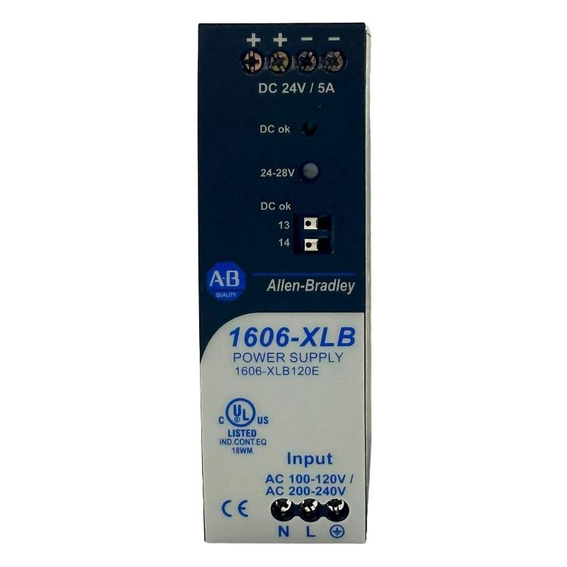
Table of Contents
- Allen Bradley 1606-XLB120E Power Supply Installation Overview
- Allen Bradley 1606-XLB120E Power Supply Application
- Allen Bradley 1606-XLB120E Installation Planning
- Allen Bradley 1606-XLB120E Cabinet and Environmental Preparation
- Allen Bradley 1606-XLB120E Power Supply Wiring
- Allen Bradley 1606-XLB120E Startup and Setup
- Allen Bradley 1606-XLB120E Commissioning and Load Validation
- Allen Bradley 1606-XLB120E Installation Field Case
- Allen Bradley 1606-XLB120E Installation FAQ
- Allen Bradley 1606-XLB120E Overall Technical Summary
Allen Bradley 1606-XLB120E Power Supply Installation Overview
Allen Bradley 1606-XLB120E installation should be treated as a DC power-system engineering task rather than a simple power connection. Before commissioning, the engineer should verify the input circuit, DC distribution design, expected load, protective devices, cabinet conditions, conductor routing, and the voltage required by the connected PLC Controller and field equipment.
The 1606-XLB120E is an Allen Bradley industrial power supply intended for control-panel applications. In an automation cabinet, a stable DC supply is essential because PLC processors, I/O Modules, communication interfaces, sensors, relays, and other control devices can react immediately to a poor power connection or an unstable DC bus.
A practical Installation Guide therefore focuses on the complete power path. The correct Setup and Commissioning process should prove that the supply remains stable not only at its own terminals but also at the actual loads connected to the DC distribution system.
Allen Bradley 1606-XLB120E Power Supply Application
In a typical industrial control cabinet, the power supply can form the DC source for automation equipment and auxiliary control circuits. Depending on the System Configuration, the DC bus may feed PLC components, remote I/O, industrial sensors, interface relays, communication equipment, and other low-voltage control devices.
The engineering challenge is often not the normal operating load but the interaction between different loads. A contactor, solenoid, relay, or other inductive device may produce a transient disturbance when switching. If the same distribution path supplies sensitive PLC or instrumentation equipment, the resulting disturbance can appear as an unrelated control-system fault.
Allen Bradley 1606-XLB120E Load Distribution Considerations
- Calculate the continuous DC current of the complete control load.
- Identify devices with startup or switching current requirements.
- Separate sensitive PLC circuits from electrically noisy loads where appropriate.
- Consider voltage drop on long DC cable runs.
- Provide suitable branch protection for downstream circuits.
- Allow reasonable capacity for planned control-system expansion.
Allen Bradley 1606-XLB120E Installation Planning
Before mounting the 1606-XLB120E, inspect the panel layout and determine the power-flow path from the incoming supply to the DC loads. The installation should allow the terminals to be accessed during commissioning and maintenance without creating unnecessary exposure to adjacent energized circuits.
Check the electrical drawings against the physical cabinet. This simple comparison frequently identifies errors before commissioning, particularly when a panel has been modified after the original design was completed.
Allen Bradley 1606-XLB120E Pre-Installation Checks
- Confirm the exact 1606-XLB120E model designation.
- Verify the designed input supply and protective arrangement.
- Confirm the DC output requirement of the connected equipment.
- Calculate the expected load current.
- Review conductor size and expected voltage drop.
- Inspect the cabinet for contamination, moisture, and excessive heat.
- Confirm that the grounding and protective-earth arrangement follows the panel design.
Allen Bradley 1606-XLB120E Cabinet and Environmental Preparation
Thermal management should be considered before commissioning. Power supplies dissipate heat during normal operation, and cabinet temperature can increase when multiple power electronics devices are installed close together.
A common field mistake is placing the power supply immediately above another heat-generating device without considering the cabinet’s airflow pattern. Even when the electrical wiring is correct, poor thermal design can reduce long-term reliability.
The mounting surface should also be mechanically stable. Excessive vibration or loose mounting hardware can eventually affect wiring connections, particularly in cabinets installed near motors, compressors, pumps, or other rotating machinery.
Allen Bradley 1606-XLB120E Power Supply Wiring
Allen Bradley 1606-XLB120E wiring should be completed with the relevant power source isolated. Identify the input terminals, DC output terminals, and protective-earth connection according to the electrical design and the markings on the installed unit.
Do not use wire color as the only method of identifying DC polarity. Trace each conductor against the panel drawing and verify polarity with suitable test equipment before connecting sensitive PLC equipment.
Allen Bradley 1606-XLB120E DC Distribution Wiring
- Route power wiring cleanly and mechanically secure all conductors.
- Keep sensitive signal wiring separated from high-noise power circuits.
- Use appropriate conductor termination methods.
- Verify positive and negative DC polarity before energizing loads.
- Inspect each terminal for proper mechanical retention.
- Keep the DC distribution layout consistent with the electrical drawings.
After wiring, perform a complete visual inspection. Look for loose conductors, incorrect polarity, damaged insulation, missing protective devices, and unintended connections between separate DC branches.
Allen Bradley 1606-XLB120E Startup and Setup
The 1606-XLB120E Setup process should begin with verification of the incoming power rather than immediately connecting the entire control system. Where the panel design permits, the power supply can initially be checked before the complete downstream load is placed into operation.
Measure the DC output directly at the supply terminals. Then compare that measurement with the voltage available at the main DC distribution point. If there is a significant difference, investigate the wiring before proceeding with full System Configuration commissioning.
Initial electrical check:

Input supply:
  Verify source voltage
  Verify protective device
  Verify conductor integrity

DC output:
  Measure at 1606-XLB120E terminals
  Measure at main DC distribution
  Compare readings

If supply voltage is stable:
  connect essential PLC loads
  monitor DC voltage
  add remaining branches progressively
  observe voltage during switching events
Allen Bradley 1606-XLB120E Commissioning and Load Validation
Commissioning should prove that the power supply can support the actual operating system, not merely that it can produce the expected voltage with no load.
Start with the PLC Controller and essential control equipment. Confirm that the processor starts normally and that connected I/O Modules remain available. After this baseline is established, introduce additional loads while monitoring the DC bus.
Allen Bradley 1606-XLB120E Commissioning Measurements
- Record the input voltage before loading the supply.
- Measure DC output voltage at the supply terminals.
- Measure voltage at the principal DC distribution point.
- Check the voltage at the most distant critical load.
- Observe the PLC Controller during load switching.
- Check remote I/O and communication stability.
- Repeat measurements after the cabinet reaches normal operating temperature.
This final temperature-related check is useful because some control cabinets operate normally during a short factory test but develop intermittent problems after several hours of continuous operation.
Allen Bradley 1606-XLB120E Installation Field Case
In one control-panel commissioning case, the initial DC measurement at the power-supply terminals was approximately 24 VDC, and the PLC Controller started normally. Several remote I/O devices were then connected during staged commissioning.
When the final group of field interface circuits was energized, the voltage at a remote distribution terminal dropped to approximately 23.0 VDC while the supply terminal remained close to its normal value. Rather than replacing the 1606-XLB120E, the commissioning engineer traced the voltage path toward the affected I/O group.
The investigation identified excessive resistance in a distribution connection combined with a relatively long DC conductor run. The problem was not visible during the initial no-load test because the voltage drop became significant only after the additional loads were energized.
After the distribution connection was corrected and the load path was improved, the remote DC voltage remained considerably more stable during normal operation.
This type of case demonstrates why installation validation must include measurements at the load. A power supply can be functioning correctly while the equipment connected to it still experiences an inadequate DC supply.
Allen Bradley 1606-XLB120E Installation and Commissioning FAQ
What is the most important check before Allen Bradley 1606-XLB120E commissioning?
Confirm the input power, output requirements, load calculation, wiring polarity, protective arrangement, conductor sizing, and cabinet conditions before applying normal operating load.
Why should voltage be checked at both the power supply and PLC equipment?
The voltage at the power-supply terminals does not necessarily equal the voltage available at a remote PLC or Module. Cable resistance, terminal resistance, and branch loading can create measurable voltage drop.
Can inductive loads affect 1606-XLB120E control circuits?
Yes. Contactors, relays, solenoids, and other switching devices can introduce disturbances into a shared DC distribution system. Appropriate circuit separation and suppression practices should be considered during System Configuration.
What should be recorded during 1606-XLB120E Setup?
Record the measured input voltage, DC output voltage, important distribution-point voltage readings, load condition, PLC status, I/O status, and any abnormal behavior observed during switching or startup.
How can a commissioning engineer confirm that the installation is stable?
Operate the complete intended load under representative conditions and repeat voltage measurements at critical points. The PLC Controller, I/O Modules, communication equipment, and field devices should remain stable during normal switching events.
Allen Bradley 1606-XLB120E Overall Technical Summary
The Allen Bradley 1606-XLB120E Installation Guide should be applied to the complete DC power architecture rather than the power supply alone. Correct mounting, wiring, protection, load planning, and thermal considerations establish the basic installation, while measured Setup and Commissioning confirm whether the control system is actually receiving stable power.
From a field-engineering perspective, the most useful commissioning method is to compare measurements at the source and at the loads while progressively introducing the actual control equipment. This makes voltage-drop problems, wiring errors, and load-related disturbances easier to identify before they become intermittent PLC faults.
A properly validated 1606-XLB120E installation provides a dependable DC foundation for PLC Controllers, Modules, Sensors, communication equipment, and other industrial automation devices. Good commissioning records also provide valuable baseline data for future Troubleshooting and Fault Diagnosis.
“`