

ProductPRODUCT
Featured products
Contact Us
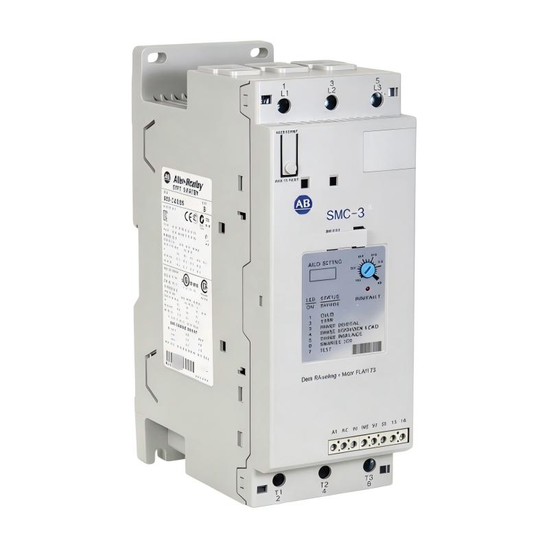
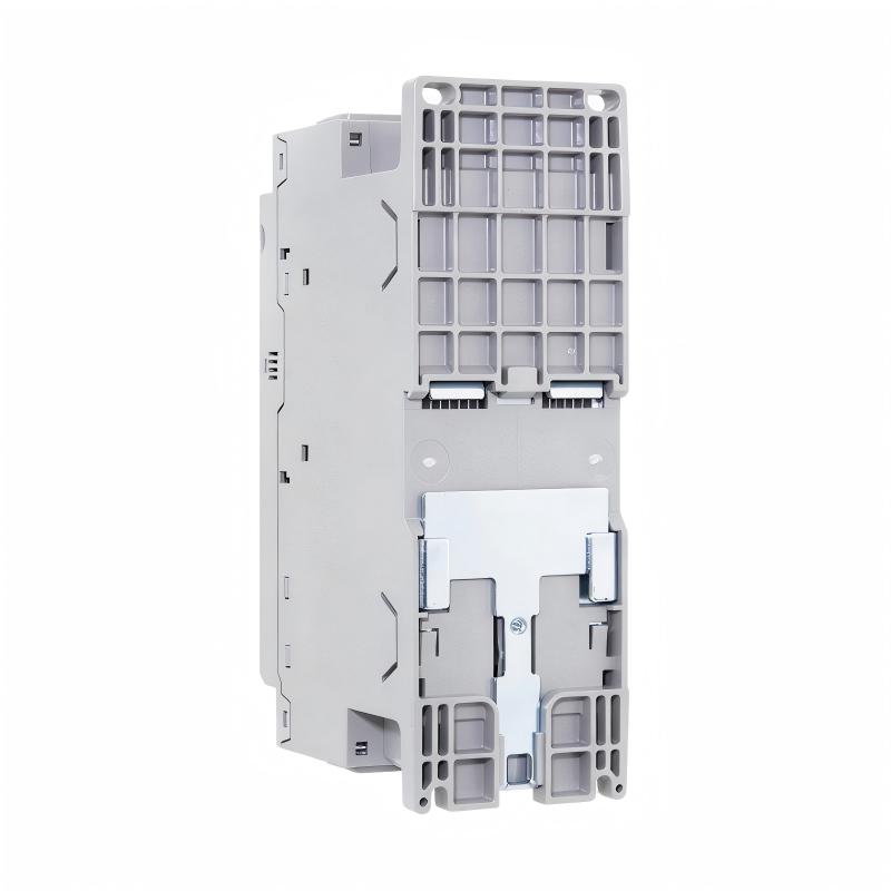
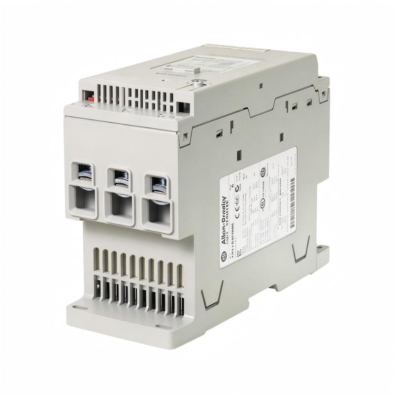
- Allen Bradley
- 150-C43NBR
- SMC-3 Smart Motor Controller
- USA
- 206 x 72 x 130 mm
- 2.25 kg
- Xiamen, China
- New & In Stock
- T/T, PayPal, Western Union
- 1 Year
- 1-3 Working Days
- DHL, UPS, TNT, FedEx and EMS.
- 24-Hour Service
- COO
- 4
Our advantage

Global Logistics
We have a 10-year logistics and express cooperation agreement, so our products can be shipped to any place in the world.

Brand new and original
Our products are imported in bulk from the place of origin. Because of the cooperative relationship, our products are all original and 100% new.

24-hour service
We provide 7*24 hours service to our customers. We will be there whenever you need us.

Price advantage
All our products are priced very favorably because we have our own warehouse and supply.
| Company Information | |||
| [email protected] | |||
| Mobile | +8615980777398 | ||
| +8615980777398 | |||
| 15980777398 |
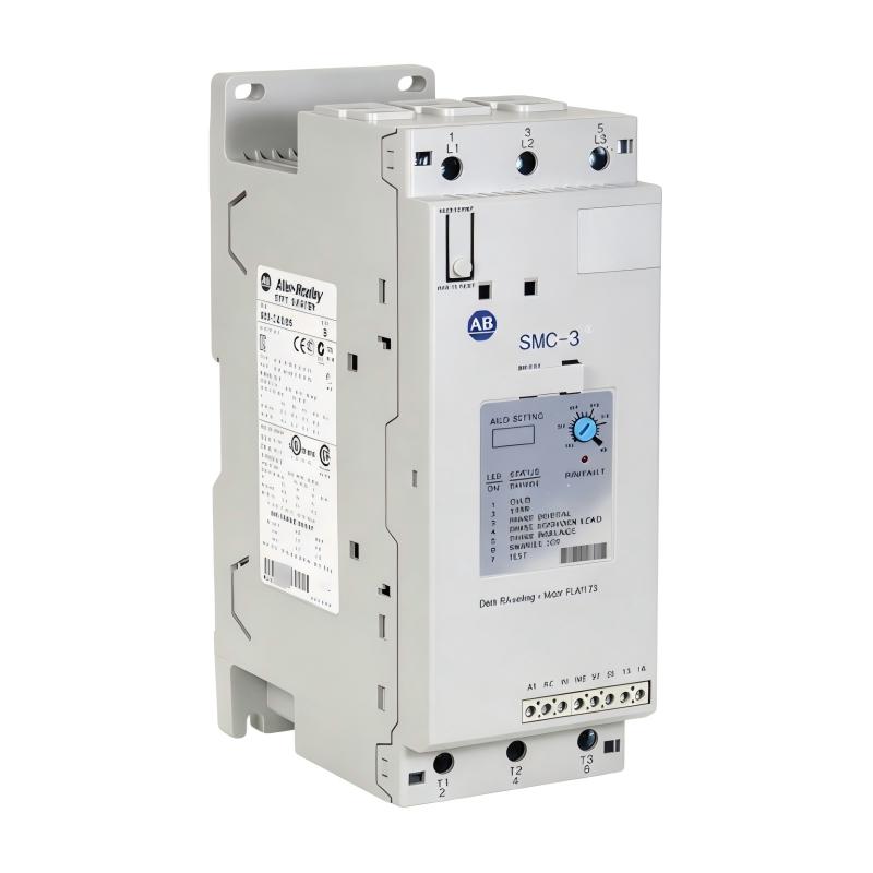
Allen-Bradley 150-C43NBR SMC-3 Smart Motor Controller – 43A Soft Starter with 24V AC/DC Control
Product Overview
The Allen-Bradley 150-C43NBR SMC-3 Smart Motor Controller is a solid-state motor controller designed to provide controlled starting and stopping for compatible three-phase AC motors. Manufactured by Rockwell Automation, this controller belongs to the Allen-Bradley SMC-3 product family and is intended for industrial motor-control applications that require dependable starting performance and integrated motor protection features.
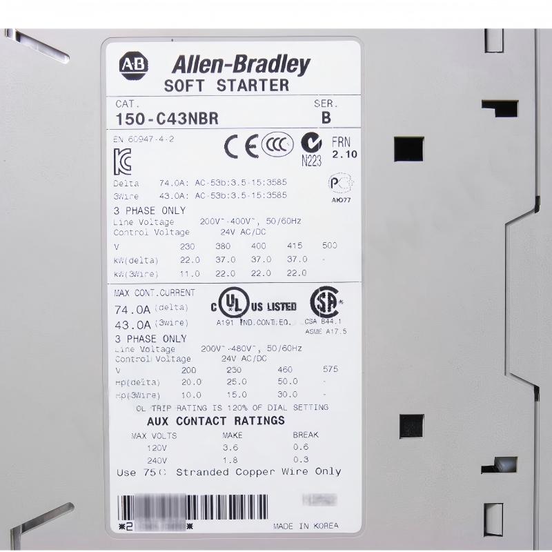
With a rated current of 43 A and a 480 V three-phase line-voltage rating, the 150-C43NBR is suitable for appropriately sized industrial motor installations. Its defining electrical characteristic is the 24 V AC/DC control supply, which distinguishes it from related SMC-3 models that use higher AC control voltages.
The controller regulates the voltage applied to the motor during starting, helping reduce the abrupt current and torque changes associated with direct-on-line starting. Depending on the application and configured settings, this can help reduce mechanical stress on couplings, belts, pumps, fans, and other driven equipment.
The SMC-3 design incorporates an internal bypass, integrated motor overload protection, adjustable starting parameters, and soft-stop functionality. These features support compact motor-control panel designs and provide useful options for industrial equipment that does not require continuous variable-speed operation.
The Allen-Bradley 150-C43NBR is commonly considered for applications involving pumps, fans, conveyors, and general manufacturing machinery. Correct selection requires checking motor current, supply voltage, starting duty, control-circuit voltage, and the applicable protection coordination requirements.
For maintenance engineers, electrical contractors, and industrial spare-parts buyers, the 150-C43NBR is a specialized motor-starting component. Its control-voltage requirement is especially important during replacement: a 24 V AC/DC control circuit must not be confused with a 100–240 V AC control circuit simply because both controllers share the same current rating and product family.
Technical Specifications
| Parameter | Specification |
|---|---|
| Brand | Allen-Bradley |
| Manufacturer | Rockwell Automation |
| Model Number | 150-C43NBR |
| Product Family | SMC-3 |
| Product Type | Smart Motor Controller / Soft Starter |
| Rated Current | 43 A |
| Line Voltage Rating | 480 V AC |
| Phase | Three-phase |
| Frequency | 50/60 Hz |
| Control Voltage | 24 V AC/DC |
| Wiring Configuration | Three-wire |
| Enclosure Type | Open type |
| Starting Duty | 350% |
| Internal Bypass | Yes |
| Integrated Motor Overload Protection | Yes |
| Motor Direction | Single direction |
| Selectable Overload Trip Class | Class 10, 15, or 20 |
| Dimensions | 206 × 72 × 130 mm |
| Weight | 2.25 kg |
| Typical Applications | Pumps, fans, conveyors, and industrial motor-driven equipment |
The specifications above describe the 150-C43NBR model. The 480 V line-voltage rating and 24 V AC/DC control requirement should be checked against the actual controller label and the installation documentation before commissioning.
Function and Working Principle
1. Solid-State Motor Starting
When an AC motor starts directly across the power supply, the initial current can be several times higher than its normal operating current. The resulting electrical demand and sudden torque can affect both the power system and the connected mechanical equipment.
The Allen-Bradley 150-C43NBR uses solid-state switching to control motor voltage during the starting process. By managing the voltage applied to the motor, it helps control acceleration and reduce abrupt changes in torque.
This can be useful in applications where smooth acceleration is desirable, such as pumping systems, ventilation equipment, and conveyor machinery.
A soft starter is different from a variable frequency drive. The 150-C43NBR is designed primarily to control motor starting and stopping, rather than to provide continuous variable-speed regulation during normal operation.
2. Adjustable Starting Torque
The SMC-3 controller provides selectable initial torque settings of 15%, 25%, 35%, and 65% of locked-rotor torque.
These settings allow the starting profile to be adjusted for different mechanical loads. A lightly loaded fan may require a different starting characteristic from a conveyor carrying material or a pump operating under process pressure.
The initial torque setting should provide enough torque to accelerate the motor reliably without imposing unnecessary mechanical stress. If the setting is too low, the motor may accelerate slowly or fail to start under load.
3. Current-Limit and Starting-Time Configuration
The SMC-3 family provides selectable current-limit settings of 150%, 250%, 350%, and 450% of full-load current, along with selectable start-time settings. The exact settings should be applied according to the product’s configuration instructions and the requirements of the connected motor.
Current limiting can help control the current drawn during starting, but it also affects the torque available to accelerate the load. The appropriate setting therefore depends on motor characteristics, load inertia, and the required acceleration time.
An excessively restrictive current limit may cause the motor to remain in the starting phase longer than expected. Settings should be validated during commissioning rather than selected solely to achieve the lowest possible starting current.
4. Kick-Start Function
Some industrial loads require additional torque at the beginning of a start cycle to overcome static friction or initial mechanical resistance.
The SMC-3 family offers a selectable kick-start function associated with 450% of full-load current, with selectable durations of 0, 0.5, 1.0, or 1.5 seconds.
This feature may be useful for suitable loads that are difficult to start with a gradual voltage ramp alone. However, kick-start should only be enabled when the application requires it, because additional starting current can increase mechanical and electrical stress.
5. Soft-Stop Function
The controller supports soft-stop functionality when configured and wired appropriately. The SMC-3 family provides selectable soft-stop durations based on the configured starting time.
Soft stopping can help reduce abrupt changes in motor operation during shutdown. For example, certain pumping applications may benefit from a more gradual reduction in motor voltage.
Soft stopping does not guarantee a specific mechanical stopping time, nor does it replace specialized braking equipment where active braking is required. The actual result depends on the motor, driven load, and system configuration.
6. Internal Bypass
The 150-C43NBR includes an internal bypass function. Once the motor has completed the starting phase and the controller enters the appropriate operating state, the bypass provides a lower-loss running path.
This reduces the continuous power dissipation associated with solid-state devices during normal operation and can simplify the overall motor-control arrangement.
The internal bypass does not eliminate the need for suitable short-circuit protection, correct conductor sizing, adequate ventilation, and compliance with the manufacturer’s installation requirements.
Role in Industrial Motor Control Systems
The Allen-Bradley 150-C43NBR is designed to operate as part of a coordinated motor-control installation. A typical system may include a three-phase supply, upstream protective devices, the soft starter, a compatible motor, and a control circuit powered by 24 V AC or 24 V DC as appropriate.
A PLC or other automation controller may issue start and stop commands through compatible control circuitry. The PLC handles process sequencing and interlocking, while the SMC-3 manages the motor-starting function according to its configured parameters.
The controller also provides integrated motor overload protection and diagnostic capabilities that can support maintenance and troubleshooting. Its auxiliary contacts can be incorporated into suitable control circuits to communicate normal-running or fault-related status, subject to the applicable wiring and contact ratings.
In a pump station, for example, a PLC may issue a start command after confirming that the required process conditions are satisfied. The 150-C43NBR then manages motor starting. Status information can be used by the wider control system to monitor operation and respond to faults.
Correct integration depends on the control-circuit design, electrical ratings, and the manufacturer’s instructions. The controller should not be treated as a substitute for all upstream short-circuit protection or for the broader safety functions of the machine.
Industrial Applications
1. Pumping Systems
Industrial pumps are used in water treatment, cooling systems, process manufacturing, and utility infrastructure. Abrupt motor starting can contribute to mechanical shock and unwanted pressure changes in some pumping installations.
The 150-C43NBR can be used for compatible pump motors when the current rating, voltage, starting duty, and load characteristics are suitable. Soft-start and soft-stop settings should be selected according to the pump and hydraulic system requirements.
2. Fans and Blowers
Fans and blowers are widely used in ventilation, dust collection, industrial cooling, and process-air systems.
A soft starter can help manage acceleration and reduce sudden mechanical loading. The 43 A rating provides a selection reference, but the motor’s nameplate current and starting conditions must still be checked.
3. Conveyor Systems
Conveyors are common in manufacturing, packaging, warehousing, and material handling.
Controlled motor starting can help reduce abrupt tension changes in belts, chains, and couplings. The 150-C43NBR may be appropriate for compatible conveyor drives where the required starting torque and acceleration time are within the controller’s capabilities.
High-inertia loads, frequent starts, and demanding acceleration cycles require particular attention during sizing.
4. Industrial Process Equipment
Mixers, auxiliary process machinery, and other motor-driven equipment may benefit from controlled starting when sudden acceleration is undesirable.
The 150-C43NBR can be considered when the application needs a fixed-frequency motor with managed starting and stopping. If continuous speed adjustment or advanced torque regulation is required, a suitable variable frequency drive may be a better choice.
5. General Manufacturing
Manufacturing facilities use electric motors in a wide range of production and utility equipment. The SMC-3 controller can support suitable motor-control panel designs where a compact soft starter is required.
Panel designers must provide adequate electrical clearances, ventilation, environmental protection, and access for inspection and maintenance.
Installation and System Integration
Step 1: Confirm the Model and Control Voltage
Verify the complete catalog number: 150-C43NBR. Confirm that the installed control circuit provides the required 24 V AC/DC supply.
This step is essential when replacing a related SMC-3 controller. A model with the same current rating but a different control-voltage suffix may require a different control-circuit arrangement.
Step 2: Check Motor and Supply Ratings
Confirm the motor’s rated voltage, full-load current, starting requirements, and the characteristics of the three-phase supply.
The 150-C43NBR is a 43 A controller with a 480 V AC line-voltage rating. These ratings do not automatically make it suitable for every motor below 43 A. Application sizing must account for starting duty, ambient temperature, load inertia, start frequency, and manufacturer guidance.
Step 3: Coordinate Protective Devices
Select appropriate short-circuit protection and verify coordination with the controller and motor. The correct protective-device arrangement depends on available fault current, conductor sizing, installation standards, and the manufacturer’s coordination tables.
Although the SMC-3 includes integrated motor overload protection, it should not be treated as a universal replacement for all upstream protective devices.
Step 4: Mount the Controller
The 150-C43NBR uses an open-type enclosure and should be installed within a suitable electrical cabinet or enclosure.
The supplied dimensions are 206 × 72 × 130 mm, and the weight is 2.25 kg. Allow sufficient space for power wiring, control wiring, ventilation, maintenance access, and the clearances specified in the installation documentation.
The manufacturer’s stated operating temperature range for the open-type controller is -5 to 50 °C, subject to the specified installation conditions and any applicable derating requirements.
Step 5: Connect Power and Control Wiring
Connect the three-phase supply, motor conductors, and control wiring according to the approved wiring diagram. Verify terminal identification, conductor sizes, grounding, and tightening torque.
The manufacturer’s listed line-power terminal conductor range is 2.5–95 mm² (14–3 AWG), and the listed load power terminal tightening torque is 11.3–12.4 Nm. Always confirm the requirements in the applicable manual before making connections.
The 24 V AC/DC control circuit must be wired according to the product documentation. Do not apply 100–240 V AC to a control terminal intended for 24 V AC/DC.
All electrical work must be performed by qualified personnel after the equipment has been placed in a safe condition.
Step 6: Configure Starting Parameters
Configure the initial torque, current limit, starting time, and any kick-start or soft-stop functions required by the application.
Settings should be selected to achieve reliable acceleration without exceeding the motor’s thermal limits or creating unnecessary mechanical stress.
Step 7: Commission and Test
After completing installation, conduct the required commissioning checks. Verify control inputs, motor rotation, starting behavior, running current, status contacts, and fault indications.
Check for abnormal heating, excessive vibration, unusual noise, and unexpected trips. Use the manufacturer’s diagnostic procedure to investigate any faults before returning the equipment to normal service.
Step 8: Document the Configuration
Record the controller model, motor nameplate information, control voltage, protection settings, starting parameters, and commissioning results.
These records help maintenance teams reproduce the approved configuration and simplify future troubleshooting or replacement.
Compatible System Components
The 150-C43NBR is normally integrated with other electrical and automation components to form a complete motor-control system.
| Component | Function | Selection Considerations |
|---|---|---|
| Three-phase AC motor | Converts electrical power into mechanical motion | Match motor current, voltage, and starting duty |
| Upstream circuit protection | Protects the installation against short-circuit conditions | Follow manufacturer coordination tables and applicable codes |
| 24 V AC/DC control supply | Provides the required control power | Verify voltage type and supply capacity |
| PLC or control relay | Issues start and stop commands | Confirm compatible control inputs and wiring |
| Push buttons and selector switches | Provide local operator commands | Match the control-circuit design |
| Auxiliary relays or contactors | Support external control and interlocking | Verify contact ratings and control voltage |
| Motor-control enclosure | Houses the controller and related components | Provide suitable ventilation and environmental protection |
| Process sensors | Provide information for process sequencing | Integrate through the appropriate PLC or control circuit |
The exact configuration depends on the motor, machine, and plant control architecture. Component selection should follow the relevant electrical drawings and installation instructions.
Replacement and Alternative Model Selection
The 150-C43NBR should not be replaced based only on its 43 A current rating or physical dimensions. Related SMC-3 models may have different control-voltage and line-voltage characteristics.
| Model | Key Difference | Replacement Consideration |
|---|---|---|
| 150-C43NBR | 43 A, 480 V AC line rating, 24 V AC/DC control | Match when these ratings meet the application requirements |
| 150-C43NBD | 43 A, 480 V AC line rating, 100–240 V AC control | Control-voltage difference must be addressed |
| 150-C43NCR | 43 A SMC-3 variant with a different line-voltage rating | Verify the exact line-voltage and control requirements |
| Other SMC-3 models | Different current ratings or electrical configurations | Confirm motor sizing, control voltage, and application suitability |
| Alternative soft starter | May use a different control architecture or feature set | Verify protection, bypass, starting duty, wiring, and mounting requirements |
These models are comparison examples, not automatic replacement recommendations. A replacement must be confirmed against the installed system’s electrical design and approved documentation.
Key Advantages of the Allen-Bradley 150-C43NBR
1. Controlled Motor Starting
Solid-state starting helps manage acceleration and can reduce the abrupt electrical and mechanical effects associated with direct-on-line starting.
2. 43 A Rated Current
The 43 A rating provides a defined selection basis for compatible three-phase motor applications, subject to proper application sizing.
3. 24 V AC/DC Control Supply
The 24 V AC/DC control requirement can suit motor-control systems designed around low-voltage control circuits. Correct control-supply matching is essential during installation and replacement.
4. Integrated Motor Overload Protection
The controller includes motor overload protection, supporting the configured motor-protection scheme when correctly selected and installed.
5. Internal Bypass
The internal bypass reduces continuous solid-state conduction losses during the appropriate running state.
6. Adjustable Starting Characteristics
Selectable torque, current-limit, kick-start, and soft-stop settings allow the controller to be configured for suitable industrial loads.
7. Compact Industrial Design
The 206 × 72 × 130 mm dimensions and 2.25 kg weight make the controller suitable for installation in appropriately designed motor-control panels.
Technical FAQs
Q1: What is the Allen-Bradley 150-C43NBR?
It is an SMC-3 Smart Motor Controller designed for controlled starting and stopping of compatible three-phase AC motors.
Q2: What is the rated current?
The rated current is 43 A. The correct application depends on the motor nameplate current, voltage, starting duty, and installation conditions.
Q3: What control voltage does the 150-C43NBR use?
It uses a 24 V AC/DC control supply. This is a key distinction from the 150-C43NBD, which uses 100–240 V AC control.
Q4: What is its line-voltage rating?
The manufacturer identifies the 150-C43NBR as a 480 V AC three-phase SMC-3 controller. Verify the product label and documentation for the exact application.
Q5: Does the controller include an internal bypass?
Yes. The internal bypass reduces continuous losses associated with solid-state conduction during the appropriate running condition.
Q6: Does it provide motor overload protection?
Yes. Integrated motor overload protection is listed as a product feature. The protection settings and overall coordination must still be appropriate for the motor and installation.
Q7: Can the 150-C43NBR continuously regulate motor speed?
No. It is a soft starter, not a variable frequency drive. Continuous speed regulation generally requires a suitable variable frequency drive.
Q8: Can it be used for pumps, fans, and conveyors?
Yes, when the motor and load requirements fall within the controller’s ratings and starting capabilities. The application must be assessed for current, voltage, load inertia, and starting frequency.
Q9: What are its dimensions and weight?
The dimensions are 206 × 72 × 130 mm, and the weight is 2.25 kg.
Q10: Can the 150-C43NBD replace the 150-C43NBR?
Not as a simple like-for-like replacement without reviewing the control circuit. The 150-C43NBD uses 100–240 V AC control, while the 150-C43NBR uses 24 V AC/DC control. Any substitution must be evaluated against the system design.
Procurement and Maintenance Recommendations
For industrial maintenance departments and spare-parts buyers, the Allen-Bradley 150-C43NBR should be sourced according to the exact requirements of the installed motor-control system.
Before ordering, verify the complete catalog number, rated current, line voltage, control voltage, and product condition. In particular, check that the offered controller is the 24 V AC/DC version rather than a similar SMC-3 model intended for a different control supply.
For replacement work, compare the existing unit’s label and wiring diagrams with the proposed replacement. Confirm that the motor current, starting duty, protective-device coordination, and mounting arrangement remain suitable.
For international procurement, ask the supplier to confirm availability, warranty, packaging, and delivery lead time. Where a controller is sold as surplus or refurbished, clarify its inspection and testing status before purchase.
Maintenance records should include the model number, control-supply details, motor data, configured starting parameters, and commissioning results. These records help prevent future replacement errors and reduce troubleshooting time.
Any work inside motor-control equipment must be performed by qualified personnel using the applicable electrical isolation and safety procedures. Follow the manufacturer’s instructions for installation, testing, and maintenance.
Conclusion
The Allen-Bradley 150-C43NBR SMC-3 Smart Motor Controller is a 43 A solid-state soft starter designed for compatible three-phase motor applications with a 480 V AC line-voltage rating and a 24 V AC/DC control supply. Its internal bypass, integrated overload protection, and adjustable starting functions support a range of industrial motor-control requirements.
For procurement and replacement, the most important factors are motor compatibility, control voltage, line-voltage rating, starting duty, and protection coordination. By confirming these details before installation, users can reduce the risk of incorrect substitutions and support reliable operation of their industrial motor-control systems.