

ProductPRODUCT
Featured products
Contact Us
- Allen Bradley
- 1756-PAR2K
- ControlLogix Redundant Power Supply Kit
- USA
- 300 x 50 x 200 mm
- 0.907 kg
- Xiamen, China
- New & In Stock
- T/T, PayPal, Western Union
- 1 Year
- 1-3 Working Days
- DHL, UPS, TNT, FedEx and EMS.
- 24-Hour Service
- COO
- 5
Our advantage

Global Logistics
We have a 10-year logistics and express cooperation agreement, so our products can be shipped to any place in the world.

Brand new and original
Our products are imported in bulk from the place of origin. Because of the cooperative relationship, our products are all original and 100% new.

24-hour service
We provide 7*24 hours service to our customers. We will be there whenever you need us.

Price advantage
All our products are priced very favorably because we have our own warehouse and supply.
| Company Information | |||
| [email protected] | |||
| Mobile | +8615980777398 | ||
| +8615980777398 | |||
| 15980777398 |
Product Overview
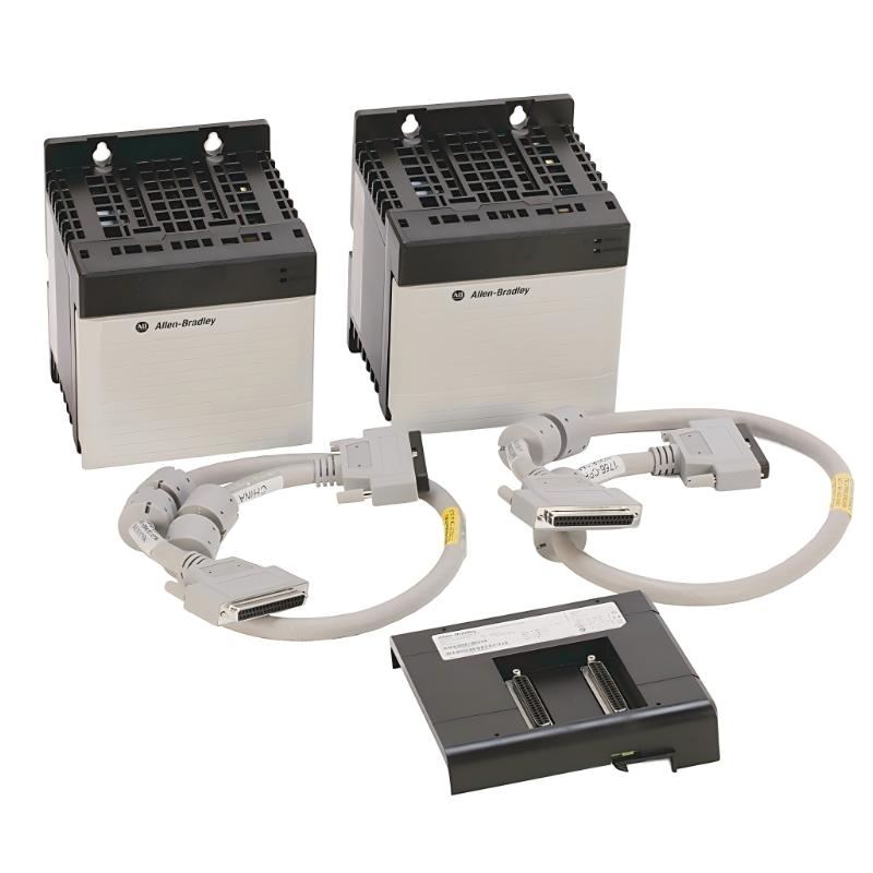
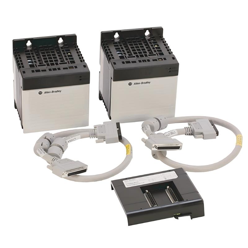
The Allen-Bradley 1756-PAR2K ControlLogix Redundant Power Supply Kit is an industrial power supply assembly designed to improve power availability in compatible ControlLogix programmable automation systems. Manufactured by Rockwell Automation, this kit combines redundant power supplies with the connection cables and chassis adapter required for the specified redundant power architecture.
In industrial automation, a stable power supply is essential for maintaining the operation of controllers, input/output modules, communication interfaces, and other chassis-based components. An unexpected power supply failure can interrupt control operations and affect production continuity. A redundant power supply configuration helps reduce the risk of a single power supply failure interrupting the system, provided the installation is designed and configured correctly.
The 1756-PAR2K is designed for applications requiring an AC-powered redundant supply arrangement. According to the manufacturer’s product information, the assembly includes two redundant power supplies, two connection cables, and a chassis adapter. The kit uses an input voltage range of 85–265 V AC and is identified as a conformally coated configuration.
Unlike a standalone power supply, this kit should be evaluated as a complete system component. Buyers must verify that the supplied components match the intended ControlLogix chassis, power requirements, and installation design.
For industrial maintenance teams, automation engineers, and spare-parts procurement specialists, the 1756-PAR2K can be relevant to new system installations, maintenance inventory, and replacement projects involving compatible ControlLogix equipment.
The dimensions and weight supplied for this listing are 300 × 50 × 200 mm and 0.907 kg. These are retained as the listing parameters and should be checked against the actual kit before finalizing enclosure layout or shipping arrangements.
Technical Specifications
| Parameter | Specification |
|---|---|
| Brand | Allen-Bradley |
| Manufacturer | Rockwell Automation |
| Model | 1756-PAR2K |
| Product Series | ControlLogix |
| Product Type | Redundant Power Supply Kit |
| Input Voltage Range | 85–265 V AC |
| Input Frequency | 47–63 Hz |
| Configuration | Redundant power supply assembly |
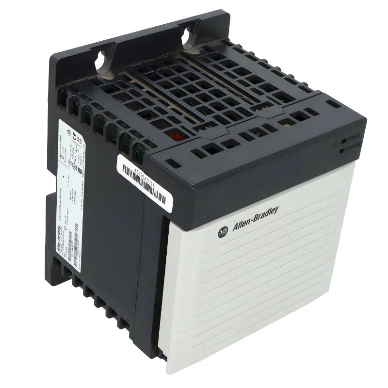
| Included Power Supplies | 2 × 1756-PA75R |
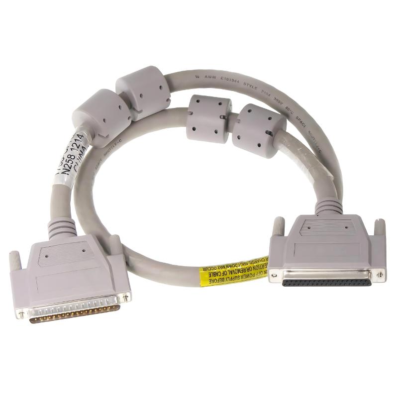
| Included Connection Cables | 2 × 1756-CPR2 |
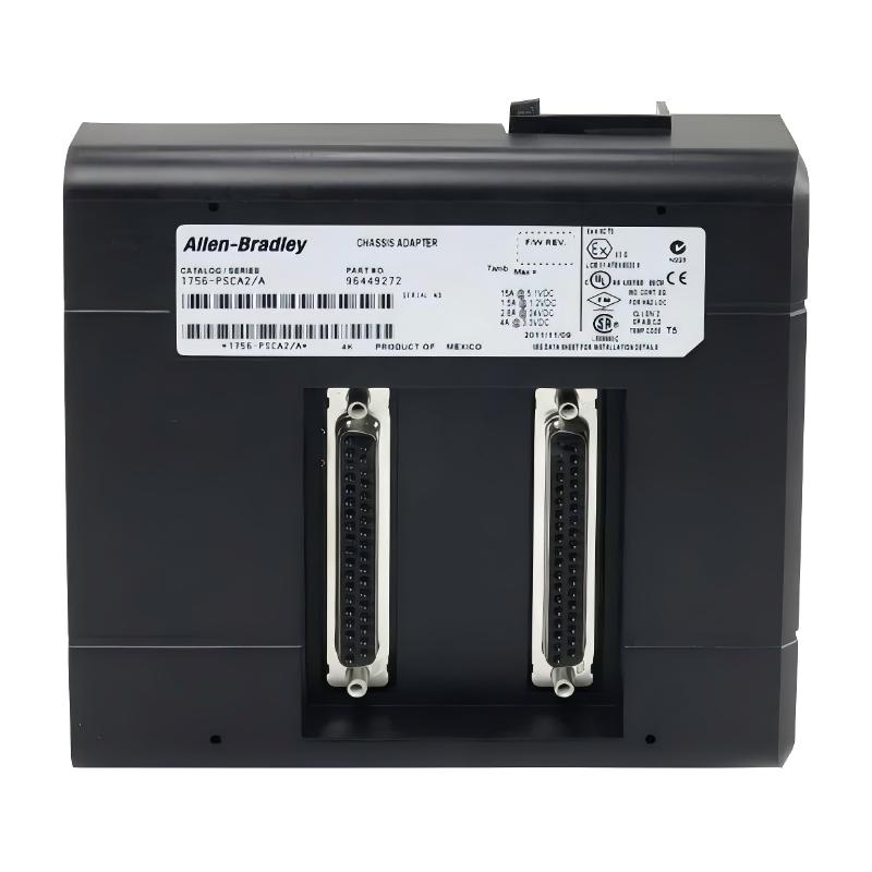
| Included Chassis Adapter | 1 × 1756-PSCA2 |
| Output Ratings | Includes 5 V DC at 13 A and 3.3 V DC at 4 A; refer to the complete supply specifications for all output rails |
| Rated Power | 75 W per compatible power supply, subject to the manufacturer’s operating conditions |
| Protective Coating | Conformally coated configuration |
| Installation | Compatible ControlLogix chassis and approved redundant power arrangement |
| Dimensions Supplied | 300 × 50 × 200 mm |
| Weight Supplied | 0.907 kg |
| Primary Function | Redundant power delivery for compatible ControlLogix systems |
The dimensions and weight shown above are the values supplied for this product listing, not independently verified mechanical specifications for the complete kit. The exact power supply revision, chassis compatibility, and complete output ratings should be confirmed before installation.
Function and Working Principle
The primary purpose of the 1756-PAR2K is to provide redundant power for a compatible ControlLogix chassis. It uses two power supplies connected through the appropriate cables and chassis adapter to support the designated redundant power architecture.
1. AC Input Power Conversion
Each power supply receives AC input power within its specified operating range and converts it into regulated DC outputs for the compatible ControlLogix system.
These DC outputs supply the chassis backplane and support the operation of installed modules. The individual output rails have defined current limits that must not be exceeded.
2. Redundant Power Architecture
The kit includes two 1756-PA75R power supplies. In a correctly configured redundant arrangement, both supplies participate in the system’s power architecture so that a single supply failure does not necessarily cause an immediate loss of chassis power.
The actual behavior depends on the supported chassis, adapter, cable connections, installation configuration, and operating conditions. Redundancy does not protect against every possible power interruption or component failure.
3. Chassis Adapter and Connection Cables
The two 1756-CPR2 cables connect the power supplies to the 1756-PSCA2 chassis adapter. The adapter provides the required interface for the supported redundant supply arrangement.
Using the specified components helps ensure that the power architecture follows the manufacturer’s design. Substituting cables or adapters without confirming compatibility can prevent correct operation.
4. DC Power Distribution
The power supplies deliver regulated DC power to the supported ControlLogix chassis. The installed controller, communication modules, and I/O modules draw power from the chassis backplane according to their individual requirements.
When planning a system, engineers must calculate the current requirements for each supported output rail and verify that the power arrangement can supply the installed modules.
5. Power Status and Fault Management
The power supplies provide status information that can help maintenance personnel identify abnormal operating conditions. Depending on the configuration, technicians may use the available indicators and system diagnostics to investigate power supply faults.
Redundant power should be treated as one part of the overall reliability strategy. The input power source, circuit protection, grounding, wiring, chassis, and control system must also be properly designed and maintained.
Role in Industrial Control Systems
The 1756-PAR2K supports power availability in ControlLogix automation installations. It is especially relevant to systems where an interruption in controller or I/O operation can affect production, process stability, or equipment availability.
ControlLogix Chassis Power
A ControlLogix chassis provides the physical and electrical platform for supported controller, communication, and I/O modules. These modules depend on the chassis power system for regulated DC power.
The redundant power kit supplies the designated power architecture for compatible chassis configurations. Engineers must verify that the chassis model and series support the intended redundant arrangement.
Production Continuity
In manufacturing and process facilities, an unexpected power supply failure can interrupt machine sequences, monitoring, or communication between automation components. A correctly installed redundant power arrangement can reduce the likelihood that the failure of one power supply alone will cause a loss of chassis power.
The actual effect on production depends on the system design and the behavior of the connected equipment.
Automation System Reliability
A redundant power supply arrangement can be part of a broader strategy for improving system availability. Other measures may include reliable input power, appropriate circuit protection, environmental control, preventive maintenance, and documented recovery procedures.
Redundant supplies do not eliminate the need for routine inspections or the replacement of aging components.
Maintenance and Spare-Parts Management
For maintenance teams, identifying the full kit number is important because the assembly contains several components that work together. Replacing only one supply, cable, or adapter may be appropriate in some circumstances, but the replacement must match the installed configuration.
Keeping the complete catalog number and component inventory in maintenance records helps reduce errors when ordering spare parts.
Industrial Applications
1. Manufacturing Automation
Manufacturing lines often rely on ControlLogix controllers to coordinate machinery, sensors, actuators, and production sequences. A redundant power supply arrangement can help improve power availability for compatible chassis-based control systems.
2. Process Control Systems
Industrial process facilities use PLC-based control systems to monitor equipment status, process conditions, and operating sequences. A redundant power architecture may be appropriate where maintaining controller and I/O availability is important.
3. Material Handling Equipment
Conveyor systems, sorting equipment, and automated material handling installations may use ControlLogix platforms for sequence control and equipment coordination. The redundant power kit can support the designated chassis configuration when required by the system design.
4. Industrial Utilities
Pumping stations, ventilation equipment, and other industrial utility systems may use ControlLogix controllers to coordinate motors, valves, and monitoring devices. Redundant power can form part of the system’s availability strategy.
5. Critical Automation Installations
Where unplanned downtime is costly, engineers may design control cabinets with redundant power components. The 1756-PAR2K can be considered for compatible installations that require its specified AC input and redundant supply configuration.
The appropriate redundancy strategy depends on the consequences of power loss, the process requirements, and the overall control system architecture.
Installation and System Integration
Correct installation is essential to ensure reliable operation and compatibility with the ControlLogix system.
1. Verify the Complete Catalog Number
Confirm that the kit is identified as 1756-PAR2K. Do not confuse it with 1756-PAR2, 1756-PBR2, or individual power supply models. Similar catalog numbers can represent different input types, power arrangements, or bundled components.
Check the label on the kit and verify the catalog numbers of the supplied power supplies, cables, and chassis adapter.
2. Confirm Chassis Compatibility
The redundant power supply kit must be used with a compatible ControlLogix chassis and the specified redundant power arrangement. Check the chassis model, series, mounting configuration, and manufacturer installation documentation before beginning the installation.
A chassis that accepts a conventional power supply is not automatically compatible with every redundant power configuration.
3. Verify AC Input Requirements
Confirm that the available input supply falls within the documented 85–265 V AC range and the specified frequency range. Check protective grounding, branch-circuit protection, conductor sizing, and local electrical requirements.
Do not apply power until the input wiring and installation have been inspected by qualified personnel.
4. Install the Specified Cables and Adapter
The kit includes two 1756-CPR2 cables and one 1756-PSCA2 chassis adapter. Install these components according to the manufacturer’s instructions.
Verify that each cable is connected to the correct component and that all connectors are fully seated. Avoid modifying or replacing the specified connection arrangement without documented approval.
5. Check DC Power Requirements
Before energizing the system, confirm the current requirements of the installed ControlLogix modules. Review the supply ratings and ensure that each output rail can support the connected load.
A redundant configuration should be designed according to the manufacturer’s power calculation and chassis loading guidance.
6. Provide Appropriate Environmental Conditions
Install the equipment in an enclosure that meets the requirements for temperature, humidity, contamination, and mechanical protection. Ensure that the installation provides the necessary ventilation and access for maintenance.
The dimensions supplied for this listing are 300 × 50 × 200 mm. Confirm the actual dimensions of the complete assembly and its individual components before finalizing the cabinet layout.
7. Perform Commissioning Checks
After installation:
- Confirm the correct catalog numbers for all kit components.
- Verify the AC input wiring and grounding.
- Check cable and chassis adapter connections.
- Confirm the chassis and installed modules are compatible.
- Inspect power supply status indicators.
- Verify that the system operates normally with the intended redundant configuration.
- Follow the manufacturer’s procedure for testing the response to a power supply fault.
- Record the configuration and test results for maintenance.
Any test that involves removing power from a supply should be performed only under an approved procedure, with appropriate process safeguards in place.
Compatible System Components
The following components are associated with the 1756-PAR2K kit and its intended ControlLogix application.
| Component | Model | Function |
|---|---|---|
| Redundant AC Power Supply | 1756-PA75R | Provides regulated DC power from AC input |
| Redundant Power Supply Cable | 1756-CPR2 | Connects a power supply to the chassis adapter |
| Redundant Power Supply Chassis Adapter | 1756-PSCA2 | Provides the interface for the redundant power arrangement |
| ControlLogix Chassis | Compatible chassis specified by Rockwell Automation | Hosts the supported controller and I/O modules |
| ControlLogix Controller | Model selected for the application | Executes automation logic |
| Digital I/O Modules | Compatible 1756-series modules | Interface with discrete field devices |
| Analog I/O Modules | Compatible 1756-series modules | Interface with analog field signals |
| Communication Modules | Compatible 1756-series modules | Support communication with external systems |
| Input Circuit Protection | Selected for the installation | Protects the AC supply circuit according to applicable requirements |
The kit’s included components should be checked against the supplied package and product label. The remaining items are system components selected according to the actual ControlLogix installation.
Alternative Models and Replacement Considerations
Several Allen-Bradley products provide power for ControlLogix systems, but they are not necessarily interchangeable. Selection depends on the input power source, redundancy requirements, chassis compatibility, and the current demands of the installed modules.
| Model | General Description | Main Difference |
|---|---|---|
| 1756-PAR2K | Redundant AC power supply kit | 85–265 V AC input; includes two supplies, two cables, and one chassis adapter |
| 1756-PAR2 | ControlLogix redundant AC power supply kit | Different catalog number and kit specification; verify the complete supplied configuration |
| 1756-PBR2 | ControlLogix redundant DC power supply kit | Intended for a DC input power architecture |
| 1756-PA75R | Redundant AC power supply module | Individual supply rather than the complete kit |
| 1756-PB75R | Redundant DC power supply module | Individual DC-input supply for a compatible system |
These products are comparison options, not automatic direct replacements.
Replacement Checklist
Before ordering a replacement, confirm:
- The complete catalog number and product label.
- Whether the requirement is for the full kit or an individual power supply.
- Input voltage and frequency.
- Chassis model and series compatibility.
- Required power output and module loading.
- Cable and adapter catalog numbers.
- Conformal coating requirements.
- Physical dimensions and mounting arrangements.
- Condition, revision, and included accessories.
For an existing installation, the safest approach is to compare the replacement against the original assembly and the system’s approved configuration rather than relying only on the product family name.
Key Advantages
Redundant Power Architecture
The kit provides two power supplies in a supported redundant arrangement, helping reduce the risk of a single power supply failure interrupting the chassis power system.
Wide AC Input Range
The specified 85–265 V AC input range supports installations designed around the manufacturer’s documented supply requirements.
Integrated Kit Components
The inclusion of two power supplies, two connection cables, and a chassis adapter provides the principal components needed for the designated redundant power arrangement.
ControlLogix System Integration
The kit is designed for compatible ControlLogix chassis installations, allowing it to be considered as part of a structured PLC power architecture.
Conformally Coated Configuration
The product is identified as conformally coated. This coating can provide additional protection for electronic assemblies against certain environmental contaminants, but it does not remove the need to observe the manufacturer’s environmental limits.
Maintenance Planning
The complete catalog number makes it easier to identify the intended kit and distinguish it from individual power supplies or DC-input alternatives.
Technical FAQs
1. What is the Allen-Bradley 1756-PAR2K?
The 1756-PAR2K is a ControlLogix redundant power supply kit designed for compatible chassis-based automation systems.
2. What components are included in the kit?
The manufacturer’s product description identifies two 1756-PA75R power supplies, two 1756-CPR2 cables, and one 1756-PSCA2 chassis adapter.
3. What is the input voltage range?
The specified AC input range is 85–265 V AC. The actual installation must comply with the power supply’s nameplate and the manufacturer’s installation requirements.
4. What is the purpose of redundant power supplies?
A redundant arrangement helps improve power availability by reducing dependence on a single supply. The degree of protection depends on the complete system architecture and the supported configuration.
5. Is the 1756-PAR2K the same as the 1756-PAR2?
They are different catalog numbers. Their component configuration and specifications should be checked individually before selecting a replacement.
6. Can the 1756-PAR2K be used with any ControlLogix chassis?
No. Compatibility depends on the chassis model, series, and the manufacturer’s requirements for redundant power installations. Verify the approved configuration before installation.
7. What are the dimensions and weight?
The dimensions supplied for this listing are 300 × 50 × 200 mm, with a weight of 0.907 kg. These figures should be checked against the complete kit and actual packaging before being used for mechanical or shipping calculations.
8. Does the kit include the cables and chassis adapter?
Yes. The documented configuration includes two 1756-CPR2 cables and one 1756-PSCA2 chassis adapter, in addition to the two power supplies. Confirm the contents of the particular unit being purchased.
9. What maintenance is recommended?
Inspect the power supplies, cable connections, adapter, and status indicators according to the manufacturer’s maintenance guidance. Check for overheating, loose connections, contamination, and abnormal status indications.
10. What should buyers verify before ordering?
Verify the complete catalog number, input voltage, chassis compatibility, included components, product condition, and required delivery documentation. For replacement projects, compare the kit with the existing system configuration.
Procurement and Maintenance Recommendations
When sourcing the Allen-Bradley 1756-PAR2K ControlLogix Redundant Power Supply Kit, verify whether the requirement is for the complete kit or an individual power supply. The distinction is important because the kit includes the power supplies, cables, and chassis adapter needed for the documented redundant configuration.
For replacement projects, check the existing chassis model, series, power requirements, and installed module load. Confirm that the selected kit matches the original design and that all required components are present.
For maintenance inventory, retain the complete catalog number and record the models of the included supplies, cables, and adapter. Keeping this information with the control cabinet documentation can reduce procurement errors and shorten troubleshooting time.
When purchasing a new, unused, surplus, or refurbished unit, clarify the product condition and whether the complete kit has been inspected or tested. Confirm packaging protection, warranty terms, delivery lead time, and the availability of relevant documentation.
During routine maintenance, inspect the power supply connections and monitor the system for abnormal power indications. Follow the manufacturer’s procedure when testing redundant operation, and ensure that any planned test will not expose the process to an unacceptable interruption.
Conclusion
The Allen-Bradley 1756-PAR2K ControlLogix Redundant Power Supply Kit is designed to support power availability in compatible ControlLogix chassis systems. Its documented configuration includes two 1756-PA75R power supplies, two 1756-CPR2 cables, and one 1756-PSCA2 chassis adapter, with an AC input range of 85–265 V.
For procurement, installation, and maintenance, the key considerations are chassis compatibility, input voltage, module power requirements, correct cable and adapter configuration, and verification of the complete kit contents. Confirming these details against the manufacturer’s documentation helps ensure that the selected assembly meets the requirements of the intended industrial automation system.