

ProductPRODUCT
Featured products



Contact Us
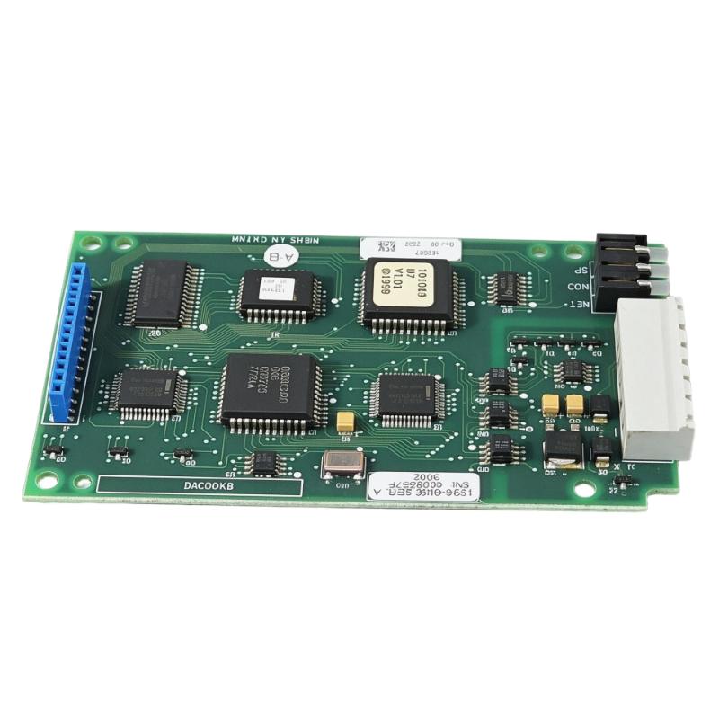
- Allen Bradley
- KALEX3K 688-94V-0
- Printed Circuit Board
- USA
- 150 x 25 x 100 mm
- 0.2 kg
- Xiamen, China
- New & In Stock
- T/T, PayPal, Western Union
- 1 Year
- 1-3 Working Days
- DHL, UPS, TNT, FedEx and EMS.
- 24-Hour Service
- COO
- 5
Our advantage

Global Logistics
We have a 10-year logistics and express cooperation agreement, so our products can be shipped to any place in the world.

Brand new and original
Our products are imported in bulk from the place of origin. Because of the cooperative relationship, our products are all original and 100% new.

24-hour service
We provide 7*24 hours service to our customers. We will be there whenever you need us.

Price advantage
All our products are priced very favorably because we have our own warehouse and supply.
| Company Information | |||
| [email protected] | |||
| Mobile | +8615980777398 | ||
| +8615980777398 | |||
| 15980777398 |
Product Overview
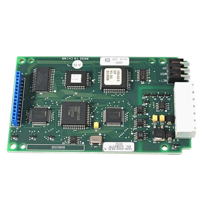
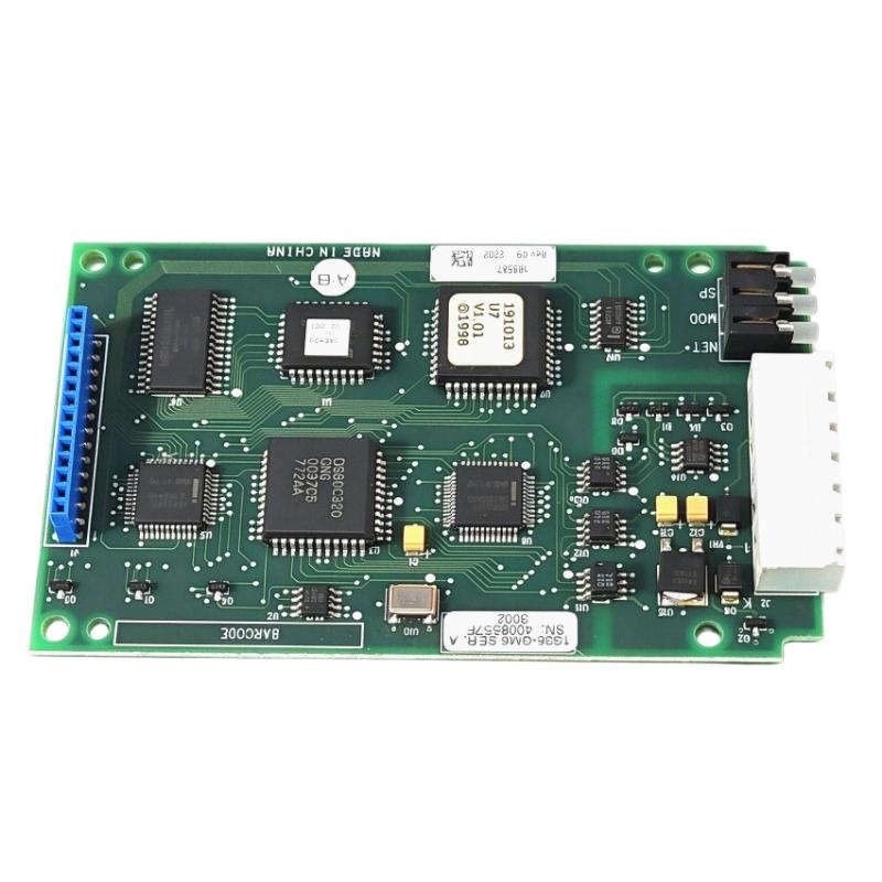
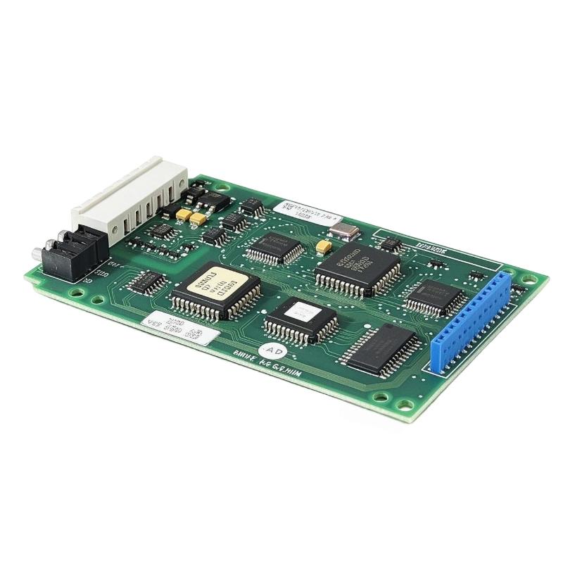
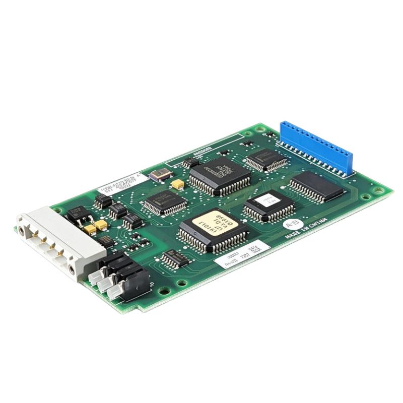
The Allen-Bradley KALEX3K 688-94V-0 Printed Circuit Board is an electronic circuit board associated with industrial control and automation equipment. Printed circuit boards provide the physical platform for mounting electronic components and establishing the electrical connections required for signal processing, control functions, and communication between circuit elements.
In industrial automation environments, circuit boards are important components of electronic control assemblies. Depending on the equipment design, a PCB may support interface functions, signal conditioning, logic processing, or communication between different sections of a machine control system. The exact role of the KALEX3K 688-94V-0 must be confirmed against the original equipment documentation and the markings on the installed board.
For maintenance teams and industrial spare-parts buyers, accurate board identification is essential. Similar-looking circuit boards can have different component layouts, connector assignments, revisions, and electrical characteristics. A correct replacement should therefore be selected using the complete part number, board markings, revision information, connector configuration, and the equipment in which it is installed.
The KALEX3K 688-94V-0 is suitable for consideration in industrial electronic spare-parts procurement where the existing assembly has been positively identified. Its compact form makes it relevant to applications in which a PCB is installed inside a larger electrical or electronic assembly.
The product information supplied for this listing specifies dimensions of 150 × 25 × 100 mm and a weight of 0.2 kg. Buyers should confirm these measurements against the actual item before finalizing mounting arrangements, shipping calculations, or replacement procedures.
Technical Specifications
| Parameter | Specification |
|---|---|
| Brand / Identification | Allen-Bradley / KALEX, as supplied in the product listing |
| Product Model | KALEX3K 688-94V-0 |
| Normalized Part Number | KALEX3K688-94V-0 |
| Product Type | Printed Circuit Board |
| Product Category | Industrial Control PCB |
| Application Category | Industrial electronic control equipment |
| Board Identification | KALEX3K / 688-94V-0 |
| Dimensions | 150 × 25 × 100 mm |
| Weight | 0.2 kg |
| Mounting Method | Determined by the original equipment design |
| Electrical Interface | Must be confirmed from the board and equipment documentation |
| Connector Configuration | Must be verified against the original board |
| Hardware Revision | Check the physical board label and markings |
| Operating Voltage | Confirm from the applicable equipment documentation |
| Installation Environment | Inside the compatible equipment enclosure |
| Replacement Requirements | Exact part-number, revision, and interface verification |
The dimensions and weight shown above are the values provided for this product listing. Electrical ratings, connector assignments, and the board’s precise function should not be assumed without supporting documentation for the exact assembly.
Function and Working Principle
A printed circuit board provides an organized electrical platform for connecting electronic components. Its conductive tracks, component mounting points, and connectors allow individual electronic devices to work together as part of a larger circuit.
The precise working principle of the KALEX3K 688-94V-0 depends on its intended application and the electronic components installed on the board. The following describes the general functions that industrial PCBs may perform rather than asserting undocumented features of this particular model.
1. Electrical Interconnection
A PCB establishes electrical paths between components such as resistors, capacitors, integrated circuits, transistors, and connectors. These paths allow signals and, where applicable, electrical power to move between designated circuit points.
The layout of these connections is determined by the board’s design. For replacement purposes, the original trace layout, component arrangement, and connector locations should match the required assembly.
2. Electronic Signal Processing
Industrial control boards may process input signals from sensors, switches, interface circuits, or other electronic assemblies. Depending on the board design, signal processing can involve filtering, conditioning, logic operations, or conversion between signal stages.
The exact signal types supported by the KALEX3K 688-94V-0 should be determined from the relevant schematic, service documentation, or the assembly in which it is installed.
3. Communication Between Components
Some PCBs provide electrical interfaces between separate control modules. Connectors and circuit traces can carry signals between a board and the host equipment.
Connector similarity alone does not establish compatibility. Pin assignments, signal levels, grounding arrangements, and the intended interface must all be checked before installation.
4. Integration Within an Electronic Assembly
A PCB normally works as part of a larger system rather than as an independent control device. It may be mounted in a chassis, connected to a main board, or incorporated into a machine’s electrical assembly.
Its overall role depends on the host equipment’s architecture and the other components connected to it.
5. Board-Level Maintenance
When an electronic assembly develops a fault, technicians may inspect its PCB for damaged components, cracked solder joints, corrosion, overheated areas, or connector damage. Depending on the repair strategy, the board may be repaired or replaced as a complete assembly.
For the KALEX3K 688-94V-0, diagnosis should be based on the host equipment’s fault symptoms and the applicable maintenance documentation.
Role in Industrial Control Systems
Printed circuit boards are essential building blocks in industrial electronics. They allow multiple electronic components to operate together within a compact assembly, supporting the larger functions of machine control and automation equipment.
Electronic Control Assemblies
Within an industrial control assembly, a PCB can provide connections and electronic functions needed by the equipment. Its role may range from a simple interface to a more specialized control or processing function, depending on the original design.
Before assigning a specific function to the KALEX3K 688-94V-0, technicians should check its equipment reference, board label, revision markings, and original parts documentation.
Machine Control Equipment
Industrial machines contain electronic assemblies that coordinate electrical signals and equipment status. A PCB installed in one of these assemblies must match the electrical and mechanical requirements of the host device.
An incorrectly selected board may fail to operate, produce unexpected faults, or damage connected components. Model verification is therefore an important part of industrial maintenance.
Electrical and Electronic Interfaces
In many systems, connectors link PCBs to sensors, control modules, displays, power circuits, or other electronic assemblies. Correct connector alignment and pin assignment are essential to maintaining the intended circuit operation.
Technicians should not assume that two boards are interchangeable simply because they share a similar outline or connector type.
Spare-Parts Management
Keeping correctly identified PCBs in maintenance inventory can help shorten repair lead times. For older equipment, a reliable identification process is especially important when documentation is incomplete or replacement options are limited.
Recording part numbers, revision codes, connector details, and equipment references helps purchasing teams source a more suitable replacement.
Industrial Applications
The KALEX3K 688-94V-0 is identified as an industrial control circuit board. Its precise end application should be established through the original equipment documentation rather than inferred from the KALEX3K marking alone.
The following are general environments where industrial printed circuit boards are commonly used.
1. Industrial Automation Equipment
Electronic boards are widely used in automation assemblies to support internal electrical connections, control electronics, and interface functions. A replacement PCB must match the requirements of the specific equipment.
2. Machine Control Cabinets
Machine control cabinets may contain multiple electronic boards alongside PLCs, relays, power supplies, terminal blocks, and communication devices. Board-level components within these cabinets should be identified by their full part numbers and installation references.
3. Manufacturing Equipment
Manufacturing machinery relies on electronic assemblies for a wide range of internal functions. A defective PCB can interrupt machine operation when the affected circuit is essential to the equipment’s normal operation.
4. Industrial Equipment Maintenance
Maintenance departments often use PCB replacement as part of fault recovery when a board cannot be repaired economically or quickly. The correct replacement must be checked for electrical, mechanical, and revision compatibility.
5. Legacy Automation Systems
Older industrial equipment may remain in service long after its original electronic components become difficult to source. In these situations, accurate board identification and condition assessment can help maintenance teams evaluate suitable spare parts.
These examples describe common industrial PCB applications. They do not independently establish the exact host machine or system for the KALEX3K 688-94V-0.
Installation and System Integration
Correct installation is necessary to prevent electrical damage and ensure that the replacement board works with the intended equipment.
1. Verify the Part Number
Before installation, compare the original board’s complete part number with the replacement. Check whether the markings read KALEX3K 688-94V-0 or KALEX3K688-94V-0, and record any additional numbers, revision codes, serial markings, or assembly identifiers.
Do not rely on a shortened model description when the original equipment documentation specifies a more detailed part number.
2. Inspect the Physical Board
Inspect the PCB for cracks, damaged connectors, corrosion, contamination, lifted pads, or signs of overheating. Check the board’s mounting points and outline against the original component.
Confirm the supplied dimensions of 150 × 25 × 100 mm against the physical board and the available installation space.
3. Follow Electrical Safety Procedures
Before accessing an installed PCB, isolate the equipment from its power source and follow the manufacturer’s lockout and verification procedures. Some assemblies may contain stored electrical energy even after the main supply has been disconnected.
Only qualified personnel should perform installation and maintenance. Electrostatic discharge precautions should be followed when handling sensitive electronic components.
4. Check Connector and Pin Assignments
Confirm that each connector matches the original arrangement. Verify pin assignments, orientation, cable routing, and any required jumpers or configuration elements.
Never force a connector into place or assume that a physically compatible connector has the same electrical pinout.
5. Verify Revision Compatibility
Circuit boards may be produced in multiple hardware revisions. A revision change can affect component selection, circuit layout, firmware requirements, or compatibility with other equipment.
Check the revision information on the original board and replacement. If the revision differs, confirm interchangeability through reliable equipment documentation before proceeding.
6. Reinstall and Secure the Board
Use the mounting hardware and installation method specified for the host equipment. Ensure that the board is properly seated and that connectors are secured without excessive force.
Avoid allowing cables, loose hardware, or conductive debris to contact exposed circuit areas.
7. Perform Controlled Testing
After installation, follow the host equipment’s commissioning or maintenance procedure. Check for abnormal indications, equipment fault messages, and unexpected operating behavior.
Where practical, record the replacement date, board identification, revision, test results, and any remaining maintenance issues.
Compatible System Components
The exact equipment and accessories compatible with the KALEX3K 688-94V-0 cannot be established from its part number alone. The following table lists common component categories that may be found in industrial electronic assemblies; it is not a confirmed compatibility list for this PCB.
| Component Category | Typical Role | Compatibility Checks |
|---|---|---|
| Main control board | Coordinates major electronic functions | Confirm assembly number and board revision |
| Interface board | Connects signals between circuit sections | Verify signal types and pin assignments |
| Power supply circuit | Provides required electrical power | Confirm voltage, polarity, and current requirements |
| Wiring harness | Connects boards and external circuits | Check connector type, pinout, and cable arrangement |
| Terminal or connector assembly | Provides electrical connection points | Verify part number and physical configuration |
| Chassis or mounting frame | Supports and secures electronic boards | Confirm dimensions and mounting-hole positions |
| Sensors and field devices | Supply measurements or equipment status | Verify that the host equipment supports the connected devices |
| Protective enclosure | Protects electronics from environmental hazards | Confirm clearance, grounding, and environmental requirements |
Actual compatibility should be established using the host equipment model, electrical schematics, and the original parts list.
Alternative Models and Replacement Considerations
Finding a suitable replacement for an industrial PCB requires more than identifying a board with a similar appearance. The replacement must satisfy the electrical, mechanical, and functional requirements of the original assembly.
The KALEX3K 688-94V-0 is associated with a KALEX circuit-board identification. A different board should not be described as a direct substitute unless its interchangeability has been confirmed.
| Replacement Option | When to Consider It | Verification Required |
|---|---|---|
| Exact KALEX3K 688-94V-0 board | Preferred when replacing the same identified part | Confirm complete markings and revision |
| Same part number with a different revision | When the original revision is unavailable | Confirm documented revision compatibility |
| Manufacturer-approved replacement | When an official replacement part is specified | Verify the approved replacement reference |
| Professionally repaired original board | When repair is technically and economically practical | Confirm repair quality and functional test results |
| Third-party substitute board | Only when a validated substitute is available | Confirm electrical, mechanical, and functional equivalence |
Important Replacement Checks
Before ordering a replacement, verify:
- The complete board part number.
- The host equipment model and assembly reference.
- All visible revision and identification markings.
- Connector locations and pin assignments.
- Physical dimensions and mounting points.
- Required supply voltages and electrical interfaces.
- Firmware, configuration, or calibration requirements, where applicable.
- The condition and test status of the offered replacement.
If the original board is no longer manufactured, sourcing may involve unused stock, refurbished equipment, or a repair service. The condition and test status should be confirmed before purchase.
Key Advantages
Compact Circuit Board Design
The supplied dimensions of 150 × 25 × 100 mm make this a compact board listing suitable for evaluation against the physical requirements of the target assembly.
Component-Level Integration
A PCB consolidates electrical connections and electronic components onto a single platform, allowing it to be installed within a larger control or electronic assembly.
Useful for Maintenance and Repair
A correctly identified replacement board can help maintenance teams restore equipment operation without replacing an entire electronic assembly, provided that the board is independently replaceable in the host system.
Supports Spare-Parts Identification
Using the full KALEX3K 688-94V-0 identification helps buyers distinguish the requested board from other circuit boards that may share similar markings or construction.
Suitable for Legacy Equipment Procurement
For older industrial installations, a documented part number and a careful compatibility check can help maintenance teams evaluate available spare parts and repair options.
Traceable Replacement Process
Recording the board’s part number, revision, condition, and installation details supports more consistent maintenance records and future procurement.
Technical FAQs
1. What is the KALEX3K 688-94V-0?
It is identified in product listings as a KALEX printed circuit board used in an industrial control or machine-control context. Its precise function and host equipment should be confirmed using the original equipment documentation.
2. What are the dimensions of this circuit board?
The dimensions supplied for this product listing are 150 × 25 × 100 mm. Confirm the physical measurements before preparing an installation or replacement enclosure.
3. How much does the board weigh?
The supplied product weight is 0.2 kg. Actual shipping weight may differ depending on packaging and protective materials.
4. Is the KALEX3K 688-94V-0 an Allen-Bradley product?
The product listing supplied for this page associates Allen-Bradley with the item and identifies KALEX3K688-94V-0 as the board number. The exact manufacturer and original equipment relationship should be verified from the physical board markings and equipment documentation before being stated more specifically.
5. What equipment is this PCB compatible with?
Compatibility cannot be determined reliably from the board number alone. Confirm the host equipment model, complete board number, revision, connectors, and electrical requirements before purchasing a replacement.
6. Can a similar KALEX circuit board be used as a replacement?
Not automatically. Boards with similar markings may have different circuit designs or connector assignments. Use an alternative only when its compatibility has been established.
7. What should be checked before installation?
Check the complete part number, revision, mounting dimensions, connector configuration, pin assignments, and any relevant power or signal requirements. Follow the host equipment’s safety and installation procedures.
8. How should the PCB be stored?
Store the board in suitable antistatic packaging in a clean, dry environment. Protect it from moisture, dust, electrostatic discharge, vibration, and physical impact. Follow any specific storage requirements supplied with the product.
9. Is the part discontinued?
A product listing for KALEX3K688-94V-0 reports that the manufacturer has discontinued it. Buyers should verify current availability and the offered unit’s condition with the supplier before placing an order.
10. What information should be provided when requesting a quotation?
Provide the full part number, required quantity, equipment model, preferred product condition, delivery requirements, and any applicable revision markings. Photographs of the front and back of the board and its labels can help confirm the requested item.
Procurement and Maintenance Recommendations
When purchasing the KALEX3K 688-94V-0 Printed Circuit Board, prioritize accurate identification and condition verification. The full board number should be recorded alongside all visible labels, revision codes, and additional assembly numbers.
For older equipment, the physical marking on the board may not be sufficient to establish its full function. Where possible, compare the item with the original bill of materials, service documentation, wiring diagrams, or the board removed from the equipment.
Buyers should also distinguish between new unused stock, surplus stock, refurbished boards, and repaired boards. These conditions are not equivalent, and the supplier should clearly state what is being offered and whether functional testing has been performed.
For international industrial spare-parts procurement, verify packaging protection and ensure that the PCB will be protected against electrostatic discharge and physical damage during transportation. Confirm the dimensions and weight before arranging cabinet work, inventory storage, or shipment.
Once a replacement is installed, retain the old board’s identification information and record the replacement details. These records can improve traceability and help reduce the risk of selecting an incompatible part during future maintenance.
Conclusion
The Allen-Bradley KALEX3K 688-94V-0 Printed Circuit Board is listed as an industrial control PCB associated with KALEX board identification. With supplied dimensions of 150 × 25 × 100 mm and a listed weight of 0.2 kg, it can be evaluated for maintenance and spare-parts requirements where the exact board identity has been confirmed.
Because the precise function and host-equipment compatibility are not established by the board number alone, buyers should verify the complete part number, revision, connector layout, electrical characteristics, and original equipment reference before ordering or installing a replacement. Careful identification and handling help reduce procurement errors and support reliable industrial equipment maintenance.