

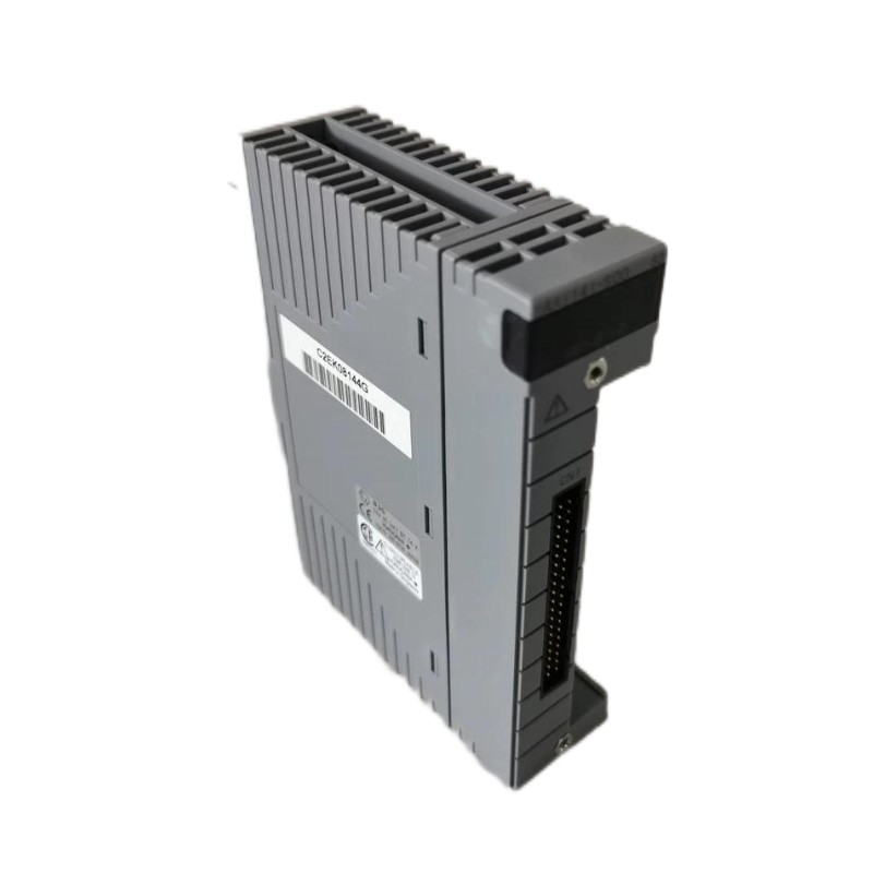
The Yokogawa AAI141-S00/K4A00 is a 16-channel, non-isolated analog input module designed to receive 4–20 mA DC signals from industrial field transmitters and transfer measured values to a Yokogawa control system. Correct installation requires attention to channel configuration, transmitter wiring, grounding, KS cable connections, and system compatibility. This guide explains the practical installation and commissioning process for the AAI141-S00/K4A00 in a distributed control system (DCS) environment.
Contents
- AAI141-S00/K4A00 Module Overview
- Technical Specifications
- Installation Preparation and Compatibility
- Hardware Installation Procedure
- 4–20 mA Transmitter Wiring
- System Configuration and Channel Setup
- Commissioning and Signal Verification
- Installation Precautions
- Technical FAQs
- Installation Summary
Yokogawa AAI141-S00/K4A00 Module Overview
The AAI141 belongs to Yokogawa’s analog input module family for field control and distributed control systems. It receives standardized 4–20 mA signals and converts them into digital process values that can be used by the field control station for monitoring, alarming, trending, and control calculations.
The AAI141-S00/K4A00 model designation identifies several important configuration details:
- AAI141: 16-channel, non-isolated analog input module for 4–20 mA DC signals.
- -S: Standard type.
- 00: Basic configuration without the optional environmental or explosion-protection suffixes.
- /K4A00: KS cable interface adapter option, associated with the ATK4A-00 interface adapter.
The KS cable interface is important when planning the physical connection between the module and the field wiring arrangement. The interface adapter and the associated cable must match the installed terminal and node configuration. The complete ordering code should therefore be checked before replacement or system expansion.
Because the AAI141-S00 is non-isolated, its input channels should not be treated as individually galvanically isolated circuits. Grounding, transmitter power arrangements, and signal reference conditions must be evaluated during engineering.
Yokogawa AAI141-S00/K4A00 Technical Specifications
| Parameter | Specification |
|---|---|
| Manufacturer | Yokogawa |
| Model | AAI141-S00/K4A00 |
| Product Type | Analog Input Module |
| Input Signal | 4–20 mA DC |
| Number of Channels | 16 channels |
| Channel Isolation | Non-isolated |
| Maximum Allowable Input Current | 27 mA |
| Input Resistance at 20 mA | Approximately 400 Ω |
| Input Resistance at 4 mA | Approximately 1000 Ω |
| Input Resistance with Power Off | 500 kΩ or higher |
| Measurement Accuracy | ±16 μA |
| Data Update Period | 10 ms |
| Step Response Time | Approximately 100 ms |
| Temperature Drift | ±16 μA per 10°C |
| Maximum Current Consumption | 310 mA at 5 V DC; 450 mA at 24 V DC |
| Transmitter Supply Capability | 14.8 V or higher at 20 mA; 26.4 V or lower at 0 mA |
| External Connection | KS cable interface option |
| Approximate Module Weight | 0.20 kg |
These are module-family specifications for the AAI141 configuration. Confirm the applicable hardware revision, system release, terminal arrangement, and installation conditions against the documentation for the actual control system before commissioning.
Preparing the AAI141-S00/K4A00 for Installation
Preparation should begin with a review of the control-system drawings and the module’s complete ordering code. A physically compatible module is not automatically suitable for every node or field wiring arrangement.
Check the installed control-system hardware
Confirm that the intended node unit or field control unit supports the AAI141 family. Check the available module slot, node configuration, power capacity, and applicable system software revision. If the module is being installed as part of a redundant arrangement, verify that the redundant configuration is supported by the selected hardware and engineering design.
Verify the KS cable interface
The /K4A00 option identifies the KS cable interface adapter. Confirm that the associated ATK4A-00 interface and KS cable are the correct parts for the installation. Check cable length, connector condition, routing, and mechanical retention before mounting the module.
Review field instrument documentation
Prepare a channel schedule showing each transmitter tag, signal type, range, wiring arrangement, and corresponding control-system channel. Confirm whether each instrument is a two-wire or four-wire transmitter. This distinction affects the transmitter power arrangement and the channel setting.
AAI141-S00/K4A00 Hardware Installation Procedure
- Isolate the relevant equipment. Follow the site’s approved electrical isolation and maintenance procedure. Confirm that the work area is safe before handling the module or its connectors.
- Inspect the module. Check the model label, connector condition, casing, and visible signs of physical damage. Do not install a module with damaged connectors or evidence of contamination.
- Confirm the mounting position. Verify the designated slot in the supported node or field control unit. Do not rely only on physical fit to determine slot compatibility.
- Install the module. Insert and secure the module according to the applicable Yokogawa hardware installation instructions. Avoid excessive force on the module or backplane connector.
- Connect the KS interface. Fit the correct KS cable and interface adapter. Check connector alignment and locking before applying power.
- Inspect the wiring route. Keep analog signal cables appropriately separated from high-energy switching conductors and other sources of electrical interference.
- Complete the installation inspection. Verify the module position, connector retention, cable identification, and terminal arrangement before restoring power.
Do not insert or remove modules under energized conditions unless the exact hardware configuration and approved maintenance procedure explicitly permit it. Hazardous-area installations require additional checks for the applicable protection concept and isolation barriers.
AAI141-S00/K4A00 4–20 mA Transmitter Wiring
The AAI141 receives current-loop signals from two-wire and four-wire field transmitters. The wiring arrangement must match the transmitter type and the channel’s configured operating mode.
Two-wire transmitter arrangement
A two-wire transmitter uses the same pair of conductors for its power supply and current signal. The AAI141 supports channel-level selection for two-wire or four-wire transmitter operation. Before wiring, confirm the correct channel setting and check that the available transmitter voltage remains sufficient after accounting for cable and device voltage drops.
Four-wire transmitter arrangement
A four-wire transmitter has a separate power supply and signal circuit. Confirm the transmitter’s output wiring polarity and connect the current output to the corresponding AAI141 input channel through the specified KS interface and field termination arrangement.
Example of a 4–20 mA signal relationship
A typical transmitter may represent a process range of 0 to 100 engineering units using a 4–20 mA output. The relationship is:
Process Value = (Measured Current - 4 mA) / 16 mA × 100
| Current Signal | Illustrative Process Value |
|---|---|
| 4 mA | 0% |
| 8 mA | 25% |
| 12 mA | 50% |
| 16 mA | 75% |
| 20 mA | 100% |
This example illustrates a common linear transmitter range. The actual engineering-unit conversion must match the instrument range and control-system configuration.
AAI141-S00/K4A00 System Configuration and Channel Setup
After hardware installation, configure the module and its channels in the engineering environment supported by the installed Yokogawa system. The exact menu names and configuration workflow depend on the system generation and software release.
Define the module in the hardware configuration
- Select the correct node and module slot.
- Identify the installed module as AAI141.
- Confirm that the module is recognized by the system configuration.
- Check whether the module’s hardware status is normal.
Configure individual input channels
For every used channel, confirm the field instrument tag, input range, transmitter type, signal scaling, engineering unit, alarm limits, and control strategy assignment. The AAI141 supports channel-level selection for two-wire or four-wire transmitter arrangements through the specified setting method.
Check the signal scaling
Scaling must correspond to the actual transmitter configuration. For example, a pressure transmitter configured for 0–10 bar should not be assigned a 0–16 bar range in the control system. Incorrect scaling can produce plausible but inaccurate process readings, making the error difficult to detect during normal operation.
AAI141-S00/K4A00 Commissioning and Signal Verification
Commissioning should verify the complete signal path, from the field transmitter to the control-system display. A successful hardware recognition test alone does not prove that the input wiring and engineering configuration are correct.
Initial hardware check
- Confirm that the module is recognized in the correct slot.
- Check module status and system diagnostic indications.
- Verify that the KS cable and interface adapter are securely connected.
- Confirm that the node and field control unit report normal operating status.
Loop test
Use an approved loop calibrator or transmitter test procedure to verify selected channels. Where permitted by the process and maintenance procedure, apply representative current values such as 4 mA, 12 mA, and 20 mA. Compare the measured current with the value displayed by the control system.
Illustrative commissioning record
| Test Point | Applied Current | Expected Scaled Value | Result |
|---|---|---|---|
| Low range | 4 mA | 0% | Record actual reading |
| Mid range | 12 mA | 50% | Record actual reading |
| High range | 20 mA | 100% | Record actual reading |
The table is a commissioning example, not a record of an actual field test. Acceptance limits should be taken from the project specification and the applicable instrument and system requirements.
Final control-system verification
Confirm that the displayed process value, alarm status, trend response, and control logic behavior are consistent with the field signal. Record the module model, slot number, channel assignments, test results, and any configuration changes in the maintenance documentation.
Important Installation Precautions for the Yokogawa AAI141
- Non-isolated inputs: Consider common-reference and grounding conditions when connecting field devices. Do not assume that each channel is galvanically isolated.
- Intrinsic safety: Yokogawa specifies that a Zener barrier must not be connected to this module. Use an appropriate isolation barrier for intrinsically safe applications, following the approved hazardous-area design.
- Transmitter voltage: Check the transmitter’s minimum operating voltage and include the voltage drop in field wiring.
- Signal interference: Use suitable cable routing, shielding, and grounding practices based on the site design.
- Module handling: Protect connectors and electronic components from electrostatic discharge and mechanical damage.
- Configuration matching: Verify the complete model code and system compatibility before replacing an existing module.
Technical FAQs About the Yokogawa AAI141-S00/K4A00
1. What is the main function of the AAI141-S00/K4A00?
It receives 4–20 mA DC analog signals from field transmitters and converts them into process data for a Yokogawa control system.
2. How many input channels does the AAI141 provide?
The AAI141 provides 16 non-isolated analog input channels.
3. What does the /K4A00 option mean?
It identifies the KS cable interface adapter option associated with the ATK4A-00 interface adapter.
4. Does the AAI141-S00 accept voltage input signals?
No. The AAI141 is designed for 4–20 mA current input. Voltage-input applications require a suitable module designed for the relevant voltage signal.
5. Is the AAI141-S00 a channel-isolated module?
No. It is a non-isolated 16-channel analog input module. The grounding and reference arrangement must be considered during system design.
6. Can the AAI141 be connected to two-wire transmitters?
Yes. The module supports two-wire and four-wire transmitter arrangements, with the transmitter type selected for each channel using the specified setting method.
7. What is the data update period?
The specified data update period is 10 ms. The overall process response also depends on the transmitter, control-system processing, and communication path.
8. What is the measurement accuracy of the AAI141?
The specified input accuracy is ±16 μA. Actual loop performance also depends on the field transmitter, wiring, calibration, and operating conditions.
9. Can the AAI141 be used in a redundant configuration?
The AAI141 family supports dual-redundant configurations when the required node hardware, system configuration, and installation conditions are satisfied. Confirm the exact arrangement against the applicable system documentation.
10. What should be checked before replacing an AAI141-S00/K4A00?
Check the complete model code, module slot, node compatibility, KS interface adapter, cable arrangement, channel settings, transmitter wiring, and existing system configuration. Also record the original channel assignments before replacement.
Installation Summary for the Yokogawa AAI141-S00/K4A00
The Yokogawa AAI141-S00/K4A00 provides 16 channels of 4–20 mA analog input for industrial process monitoring and control. A reliable installation depends on correct module identification, compatible KS cable hardware, appropriate transmitter wiring, accurate channel configuration, and systematic loop testing. Particular attention should be given to its non-isolated input design and the grounding and isolation requirements of the field installation.
By completing the hardware inspection, wiring verification, configuration review, and commissioning checks in a controlled sequence, engineers can reduce installation errors and improve the reliability of analog signal acquisition in Yokogawa control systems.