
NewsNEWCENTER
Featured products
Contact Us
Yokogawa AAI135-S50 Analog Input Module Installation Guide
2026-11-20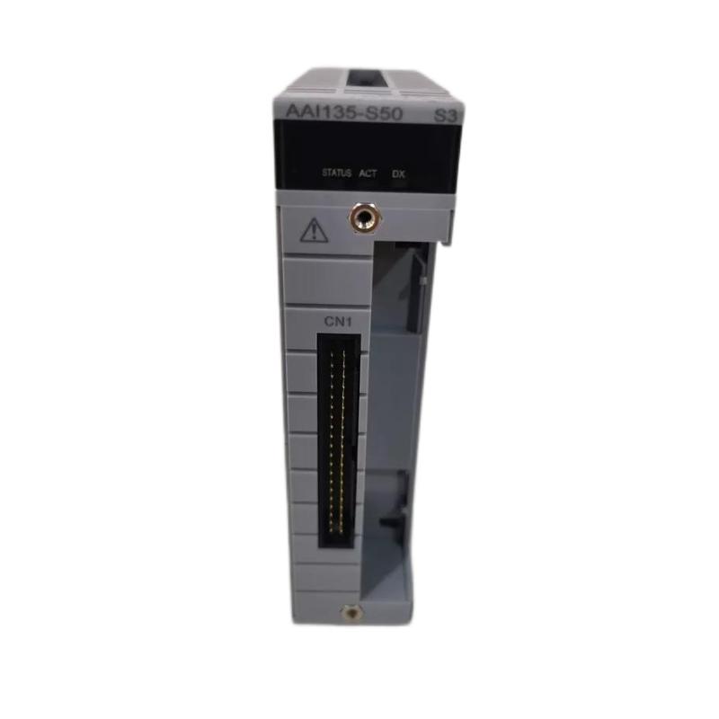
The Yokogawa AAI135-S50 is an eight-channel isolated analog input module designed to receive 4–20 mA DC signals from industrial field instruments. Used in Yokogawa CENTUM control-system architectures, it converts field current signals into process measurement data for monitoring, alarm handling, and control strategies. A reliable installation requires the correct node unit, compatible terminal hardware, verified loop wiring, and accurate channel configuration.
Yokogawa AAI135-S50 Analog Input Module Identification
The AAI135-S50 belongs to Yokogawa’s AAI135 analog input module family. It provides eight isolated current-input channels for standard 4–20 mA field signals. Typical connected instruments include pressure transmitters, flow transmitters, level transmitters, and other process devices that provide a current output.
The model suffix is important when selecting a replacement or configuring a system. The AAI135 family includes standard and HART versions. The S suffix identifies the standard type, whereas the H suffix identifies the version with HART digital communication. The S50 version is the standard, non-explosion-protected basic configuration; do not assume that it provides HART communication.
- Manufacturer: Yokogawa
- Model: AAI135-S50
- Module type: Analog Input Module
- Input signal: 4–20 mA DC
- Number of channels: 8
- Channel arrangement: Isolated channels
- Model type: Standard, non-explosion-protected basic configuration
AAI135-S50 Technical Specifications for Installation
Check the hardware specification and the exact suffix and option codes before selecting the terminal assembly or installing the module. The following values are commonly listed for the AAI135-S50 configuration; verify them against the applicable Yokogawa hardware revision and system design.
| Parameter | Specification |
|---|---|
| Input signal | 4–20 mA DC |
| Input channels | 8 |
| Channel isolation | Isolated channels |
| Maximum allowable input current | 25 mA per channel |
| Accuracy | ±16 µA |
| Data update period | 10 ms |
| Maximum current consumption | 360 mA at 5 V DC; 450 mA at 24 V DC |
| External connection options | Pressure clamp terminal, MIL connector cable, or dedicated KS1 cable |
| Approximate dimensions | 107 × 130 × 33 mm |
| Approximate weight | 0.30 kg |
Terminal hardware and cable options depend on the ordered configuration. Examples in the AAI135 family include pressure-clamp terminal assemblies and dedicated KS cable interface adapters. Confirm the complete ordering code before procurement or installation.
Yokogawa AAI135-S50 Pre-Installation Checks
Before installing the module, review the system configuration, node-unit layout, field wiring drawings, and I/O assignment schedule. The AAI135-S50 is designed for specified Yokogawa FIO node units and field control unit configurations. Mechanical fit alone does not establish system compatibility.
- Verify the complete AAI135-S50 model and revision on the nameplate.
- Confirm that the target node unit or field control unit supports the module.
- Check the terminal block, adapter, and cable option codes.
- Verify that the field instruments provide compatible 4–20 mA signals.
- Review the required channel isolation and grounding arrangements.
- Check cabinet temperature, ventilation, and environmental conditions.
- Confirm that the module’s standard non-explosion-protected specification is suitable for its installation location.
The S50 designation should not be confused with the AAI135-S53 configuration, which includes the ISA Standard G3 and extended temperature options. Select the model according to the actual environmental and project requirements.
AAI135-S50 Module Mounting and Terminal Connections
Install the AAI135-S50 in the designated slot of a compatible Yokogawa node unit or field control unit. The module must be correctly aligned with the backplane connector and secured using the specified retention mechanism.
- Confirm that the target slot is assigned to the AAI135-S50 in the hardware layout.
- Isolate the equipment as required by the approved maintenance procedure.
- Inspect the module connector and node-unit slot for damage or contamination.
- Align the module with the guide rails and connector position.
- Insert the module evenly without forcing it into the slot.
- Secure the module using the designated retention arrangement.
- Connect the approved terminal assembly or dedicated cable.
- Check that all connectors are fully seated and mechanically secure.
Do not substitute a terminal assembly or cable solely because it has a similar physical connector. The AAI135-S50 supports specified external connection arrangements, and the selected interface must match the installed hardware and wiring design.
Yokogawa AAI135-S50 4–20 mA Field Wiring Guide
Each input channel receives a current signal from a field instrument. Wiring must follow the terminal assignment for the exact terminal block, adapter, or cable option. The channel isolation design helps separate individual field signals, but it does not remove the need for correct polarity, cable routing, grounding, and loop-power arrangements.
Field wiring preparation
- Identify the transmitter tag and assigned AAI135-S50 channel.
- Confirm the instrument’s output is configured for 4–20 mA.
- Determine whether the transmitter is two-wire loop-powered or externally powered.
- Verify positive and return conductor assignments from the approved drawing.
- Check cable continuity and insulation using an approved procedure.
- Use the specified conductor size and termination method.
- Keep analog signal cables appropriately separated from high-current and switching circuits.
- Label both ends of each cable with its instrument tag and channel reference.
Do not guess terminal numbers or apply a generic pinout from another Yokogawa module. Use the connection diagram corresponding to the exact AAI135-S50 terminal arrangement. Incorrect wiring can result in missing signals, abnormal readings, or damage to connected equipment.
AAI135-S50 CENTUM System Configuration and Commissioning
After the physical installation is complete, verify that the control-system hardware configuration recognizes the AAI135-S50 in the intended node position. Each channel must correspond to the correct instrument tag, input range, and engineering-unit configuration.
- Confirm that the module is installed in the configured node slot.
- Check the system hardware status and module diagnostics.
- Verify the channel-to-instrument assignment.
- Confirm the 4–20 mA input type and intended process range.
- Configure the correct engineering units and scaling values.
- Check alarm limits and signal-quality handling.
- Verify the field transmitter’s configured range.
- Perform the approved loop test before returning the channel to service.
AAI135-S50 is the standard type rather than the HART suffix version. If digital HART communication is required, verify whether the application needs an AAI135-H series module and check the complete hardware and software compatibility before selecting a replacement.
AAI135-S50 Signal Testing and Commissioning Validation
Testing should verify the complete signal path from the transmitter to the operator display. Use an approved loop calibrator or transmitter test method, and coordinate any test that could affect process control with the operations team.
Typical 4–20 mA scaling reference
| Current input | Percentage of span | Example value for a 0–100 range |
|---|---|---|
| 4 mA | 0% | 0 |
| 8 mA | 25% | 25 |
| 12 mA | 50% | 50 |
| 16 mA | 75% | 75 |
| 20 mA | 100% | 100 |
The table shows standard linear scaling examples, not guaranteed readings from a particular installation. The actual engineering values depend on the configured transmitter and control-system range.
Final installation acceptance checklist
- Correct AAI135-S50 model and revision
- Compatible node unit and terminal connection arrangement
- Secure module installation
- Correct channel and instrument assignment
- Field wiring checked against the approved drawings
- 4–20 mA signal verified at representative points
- Engineering units and process scaling confirmed
- No unexplained hardware or channel alarms
- Commissioning measurements and approvals recorded
Yokogawa AAI135-S50 Installation FAQs
What is the Yokogawa AAI135-S50 used for?
It is an eight-channel isolated analog input module that receives 4–20 mA DC signals from field instruments and supplies process measurement data to a Yokogawa control system.
How many input channels does the AAI135-S50 provide?
The module provides eight analog input channels with channel isolation.
Does the AAI135-S50 support HART communication?
The S suffix identifies the standard type. The H suffix identifies the AAI135 version with HART digital communication. Do not assume HART capability for the S50 model.
Which signal type does this module accept?
The AAI135-S50 is designed for 4–20 mA DC analog current input signals.
Can it be installed in any Yokogawa node unit?
No. Confirm the node-unit and field-control-unit compatibility in the applicable Yokogawa hardware documentation.
What terminal connection options are available?
The AAI135 family supports specified pressure-clamp terminal arrangements, MIL connector cable configurations, and dedicated KS cable interfaces. The available option depends on the complete ordered configuration.
What is the maximum allowable input current?
The commonly listed allowable input current is 25 mA per channel. Verify the exact limit in the hardware specification applicable to the installed revision.
Does the module require calibration?
Follow the manufacturer’s maintenance and verification instructions. The connected transmitters and complete measurement loops may require periodic calibration according to the plant maintenance program.
Can the module be replaced while the system is operating?
Do not assume that live replacement is permitted in every configuration. Check the node-unit instructions, system redundancy design, and approved maintenance procedure before removing or inserting the module.
What should be checked if a channel displays an incorrect value?
Check transmitter output, loop wiring, terminal connections, channel assignment, input range, and engineering-unit scaling before concluding that the module is defective.
Yokogawa AAI135-S50 Installation Conclusion
The Yokogawa AAI135-S50 Analog Input Module provides eight isolated 4–20 mA input channels for industrial process measurement applications. Reliable operation depends on selecting a compatible node unit and terminal interface, following the correct field wiring diagram, and verifying channel scaling during commissioning. Correct model identification is particularly important when distinguishing the standard S50 version from HART and extended-environment variants. A structured installation and loop-validation process helps maintain accurate process data and dependable control-system operation.