
NewsNEWCENTER
Featured products
Contact Us
Allen-Bradley 1734-IT2I Thermocouple Input Module Troubleshooting Guide
2026-11-18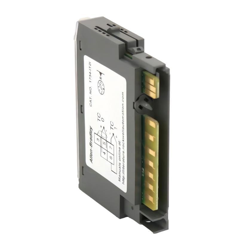
Allen-Bradley 1734-IT2I thermocouple input faults are commonly associated with incorrect sensor configuration, reversed thermocouple polarity, cold-junction compensation errors, damaged extension cables, and electrical interference. When a POINT I/O system displays an incorrect temperature or reports an input channel fault, engineers should verify the complete measurement path before replacing the input module.
The 1734-IT2I is a two-channel isolated thermocouple input module in the Allen-Bradley POINT I/O 1734 family. It accepts low-level millivolt signals and supports B, C, E, J, K, N, R, S, and T thermocouples. Because thermocouple signals are relatively small, even minor wiring problems or incorrect reference temperature compensation can affect the accuracy of the PLC temperature measurement.
Allen-Bradley 1734-IT2I Common Temperature Measurement Faults
Temperature input problems do not always produce a complete module failure. In many industrial installations, the module remains online while one channel reports an abnormal temperature or intermittent measurement.
Typical symptoms include:
- Temperature readings remain at an unexpected value.
- One channel displays an excessively high temperature.
- Temperature values fluctuate without a corresponding process change.
- Channel 0 operates normally while Channel 1 reports a fault.
- PLC input data indicates an overrange or underrange condition.
- Temperature readings differ significantly from an independent instrument.
- Thermocouple signals disappear after maintenance.
- Temperature measurements change when cabinet conditions change.
- The controller reports a module or communication status problem.
Correct Fault Diagnosis requires separating sensor problems from terminal wiring, cold-junction compensation, module configuration, and controller communication issues.
1734-IT2I Temperature Fault Diagnosis: Understanding the Measurement Chain
The most effective troubleshooting approach is to follow the temperature measurement from the physical thermocouple to the PLC tag.
Thermocouple Sensor
The sensor generates a millivolt signal according to its thermoelectric characteristics and the temperature difference between its measuring and reference junctions.
A damaged sensor, incorrect thermocouple type, or unsuitable measuring range can produce inaccurate readings before the signal reaches the I/O module.
Thermocouple Extension Wiring
Extension cables must be compatible with the thermocouple type. Using ordinary copper conductors or incompatible extension wire can introduce additional thermoelectric junctions and measurement errors.
Inspect cable continuity, polarity, shielding, and the condition of intermediate junctions.
1734-IT2I Input Processing
The module receives the millivolt signal and applies the configured thermocouple linearization and compensation. Incorrect channel settings can therefore cause inaccurate temperature conversion even when the physical input voltage is correct.
PLC Data Processing
The controller receives temperature data and associated status information. Incorrect data mapping, scaling, tag interpretation, or application logic can cause the displayed temperature to differ from the module’s actual measurement.
Allen-Bradley 1734-IT2I Thermocouple Polarity Faults
Reversed thermocouple polarity is a common wiring-related problem during initial installation and sensor replacement.
When the positive and negative conductors are reversed, the measured thermoelectric signal can have the wrong polarity. Depending on the measuring temperature and configured sensor type, the controller may report an unexpected temperature or an input range fault.
How to Identify Reversed Thermocouple Wiring
- Check the thermocouple manufacturer’s polarity identification.
- Compare the field wiring with the terminal base diagram.
- Inspect any intermediate terminal connections.
- Verify that extension cable polarity is maintained.
- Compare the reading with an independent temperature reference.
Do not identify polarity solely from conductor color. Different regional standards and cable manufacturers may use different color conventions.
Corrective Action
After isolating the relevant circuit, correct the conductor connections according to the applicable wiring documentation. Reconnect the sensor and monitor the channel status before returning the process to normal operation.
1734-IT2I Overrange and Underrange Fault Diagnosis
Overrange and underrange conditions indicate that the measured input is outside the configured or supported measurement range. These conditions can result from genuine process temperatures, incorrect sensor configuration, broken wiring, reversed polarity, or electrical interference.
Overrange Condition
An overrange indication occurs when the measured signal exceeds the applicable configured range.
Possible causes include:
- The process temperature exceeds the sensor range.
- The selected thermocouple type does not match the installed sensor.
- The input signal contains electrical interference.
- The thermocouple circuit has an abnormal connection.
- The configured engineering range is unsuitable.
Before adjusting the measurement range, verify the actual process temperature and the physical thermocouple specification. Expanding the software range will not correct an incompatible sensor or defective field circuit.
Underrange Condition
An underrange condition can occur when the input signal falls below the configured measurement range.
Investigate the following:
- Thermocouple open circuit.
- Broken extension cable.
- Incorrect polarity.
- Wrong sensor type configuration.
- Actual temperature below the configured range.
- Loose terminal connections.
Comparing Channel Status Information
The 1734-IT2I provides channel-related fault information in addition to temperature data. Engineers should inspect the module’s input status information rather than relying only on the numerical temperature displayed by the HMI.
The POINT I/O thermocouple user manual describes overrange, underrange, cold-junction, and channel fault indications. Their interpretation should be checked against the applicable module series and firmware documentation.
Allen-Bradley 1734-IT2I Cold-Junction Compensation Faults
Cold-junction compensation problems can produce consistent temperature offsets even when the thermocouple wiring and PLC communication are functioning normally.
The 1734-IT2I requires a suitable cold-junction terminal base arrangement. If the reference temperature information is incorrect or the terminal base is installed improperly, the calculated temperature may differ from the actual process temperature.
Typical Cold-Junction Problems
- Incorrect terminal base selection.
- Improper installation of the cold-junction assembly.
- Loose thermocouple connections.
- Abnormal heating around the terminal area.
- Incorrect compensation configuration.
- Unsuitable cabinet thermal conditions.
Cold-Junction Temperature Investigation
Suppose a thermocouple measures a stable process temperature, but the PLC reading changes after the cabinet door is opened or nearby equipment begins operating.
The technician should investigate the terminal area temperature and reference compensation rather than immediately replacing the thermocouple sensor.
Compare both input channels and review the cold-junction temperature information available through the module data configuration. A change in the reference temperature can affect the calculated temperature even if the process temperature remains stable.
1734-IT2I Unstable Temperature Signals and Electrical Noise
Thermocouple signals are particularly sensitive to electrical interference because their signal levels are measured in millivolts. Poor cable routing and grounding arrangements can therefore cause unstable readings in industrial cabinets.
Electromagnetic Interference Sources
Common sources of interference include:
- Variable frequency drives.
- Motor power cables.
- High-current switching equipment.
- Contactor coils.
- Welding equipment.
- Improperly grounded cable shields.
- Long parallel cable routes near power conductors.
Signal Stability Investigation
When the temperature value fluctuates, first determine whether the process temperature is genuinely changing. Compare the PLC measurement with an independent temperature instrument and observe whether the fluctuation follows the switching activity of nearby equipment.
If the temperature signal changes whenever a motor starts, for example, electromagnetic interference or grounding problems should be investigated.
Corrective Measures
- Separate thermocouple cables from high-current power cables.
- Use compatible shielded thermocouple extension wire.
- Follow the manufacturer’s shielding and grounding recommendations.
- Minimize unnecessary cable junctions.
- Check terminal tightness and conductor condition.
- Evaluate the input filter setting.
Shield grounding should follow the approved system grounding design. Connecting both ends of every shield indiscriminately can create ground-loop problems.
Allen-Bradley 1734-IT2I Incorrect Thermocouple Type Configuration
A channel can appear electrically healthy while reporting an incorrect temperature because the configured thermocouple type does not match the installed sensor.
For example, a Type J thermocouple connected to a channel configured for Type K will be interpreted using the wrong thermoelectric conversion characteristics.
Sensor Configuration Comparison
| Physical Sensor | PLC Configuration | Expected Investigation |
|---|---|---|
| Type K | Type J | Correct the sensor type selection |
| Type J | Type K | Verify the configured channel type |
| Type T | Type E | Check the sensor and extension cable identification |
| Type R | Type S | Confirm the actual thermocouple specification |
Even when two sensor types have overlapping temperature ranges, their millivolt characteristics are not interchangeable.
Configuration Recovery
- Identify the actual thermocouple model.
- Confirm the extension wire type.
- Open the module configuration in the engineering software.
- Check the sensor type for the affected channel.
- Review the configured filter and range settings.
- Apply the corrected configuration through the approved change process.
- Compare the resulting temperature with a reference instrument.
Allen-Bradley 1734-IT2I POINTBus and Communication Faults
Communication problems should be investigated when the controller cannot correctly recognize the thermocouple module or when both channels become unavailable simultaneously.
The 1734-IT2I communicates through the POINT I/O architecture. Its operation depends on the adapter, POINTBus connections, module installation, and controller hardware configuration.
Module Status Indicator Investigation
The module provides a green/red module status indicator and a green/red network status indicator. Two additional green/red indicators provide input channel status information.
When diagnosing a problem, record the actual indicator color and flashing behavior. Interpret the result using the installation documentation for the applicable series rather than assuming that every red indication represents the same fault.
Common Communication-Related Causes
- Incorrect module position in the I/O configuration.
- POINTBus connection problems.
- Damaged or poorly seated mounting base contacts.
- Incorrect module identity in the project.
- Adapter or network communication interruptions.
- Insufficient POINTBus power capacity.
If the module is not recognized after replacement, verify the complete catalog number and hardware configuration before investigating individual thermocouple channels.
1734-IT2I Diagnostic Commands and Temperature Signal Analysis
The following pseudo diagnostic sequences illustrate how an engineer can organize troubleshooting work. They are not executable Studio 5000 instructions or manufacturer-specific command syntax.
Channel Temperature Validation
MODULE: 1734-IT2I
CHANNEL: 0

CHECK 1: Read module status
CHECK 2: Read channel fault status
CHECK 3: Verify thermocouple configuration
CHECK 4: Check cold-junction information
CHECK 5: Compare input temperature with reference

IF module status is abnormal:
    Investigate POINTBus and module installation.

IF channel status indicates overrange:
    Check sensor type and input range.

IF channel status indicates underrange:
    Inspect sensor continuity and polarity.

IF channel status is normal but temperature is incorrect:
    Check linearization, cold-junction compensation,
    wiring, and PLC data processing.
Two-Channel Comparison
MODULE: 1734-IT2I

CHANNEL 0:
    Sensor: Type K
    Reading: 150.0 °C

CHANNEL 1:
    Sensor: Type K
    Reading: 165.0 °C

Reference instrument:
    Channel 0 process: 149.8 °C
    Channel 1 process: 150.2 °C

Observation:
    Channel 1 has an unexplained temperature offset.

Investigation:
    Verify sensor type.
    Inspect thermocouple extension wire.
    Check polarity.
    Verify cold-junction compensation.
    Compare raw input and channel status.
In this example, the 14.8 °C discrepancy is a diagnostic observation, not proof of a specific module failure. Further electrical and configuration checks are required to establish the root cause.
Allen-Bradley 1734-IT2I Practical Fault Investigation Case
Illustrative engineering case: Type K thermocouple measurement shows a persistent temperature offset.
A process heating system uses a 1734-IT2I module to monitor two independent temperature points. Channel 0 provides a stable reading, while Channel 1 consistently reports a temperature approximately 12 °C higher than the reference instrument.
The module is online, and there are no obvious communication faults. The maintenance team initially suspects that Channel 1 has developed an internal measurement problem.
Initial Engineering Observations
- Channel 0 temperature agrees with the reference instrument.
- Channel 1 displays a stable but incorrect value.
- Both channels are configured for Type K thermocouples.
- The module status indicator is normal.
- The error remains present after controller restart.
Root Cause Investigation
The engineer compares the physical sensor connections and discovers that Channel 1 uses an extension cable that does not match the installed thermocouple type.
Although the cable has acceptable electrical continuity, the conductor material introduces an additional thermoelectric measurement error.
The investigation demonstrates that electrical continuity alone cannot establish whether a thermocouple circuit is suitable for accurate temperature measurement.
Corrective Action and Verification
The incompatible extension cable is replaced with the appropriate thermocouple extension wire. The technician then checks polarity, terminal connections, and cold-junction compensation.
After the correction, the Channel 1 reading is compared again with the independent reference instrument under stable process conditions.
The temperature discrepancy is reduced to a level consistent with the measurement system’s applicable accuracy requirements.
This illustrative case shows why thermocouple cable material and connection quality should be included in every 1734-IT2I Fault Diagnosis procedure.
Allen-Bradley 1734-IT2I Repair and Module Replacement Assessment
Repairing a thermocouple input system does not always require repairing the electronic module itself. Many temperature measurement problems originate outside the PCB.
External Circuit Repair
Before considering module replacement, inspect:
- Thermocouple sensor condition.
- Extension wire compatibility.
- Conductor polarity.
- Terminal base connections.
- Cold-junction compensation arrangement.
- Shielding and grounding.
- POINTBus connections.
Module-Level Inspection
If external problems have been eliminated, the module can be inspected for visible physical damage, contamination, corrosion, damaged contacts, or evidence of overheating.
Internal electronic testing should be performed by qualified technicians with suitable equipment. The millivolt input circuitry is sensitive, and undocumented component replacement may introduce additional measurement errors.
When to Replace the 1734-IT2I
Replacement should be considered when an internal channel failure is confirmed, the module has physical damage, or abnormal measurement behavior persists after sensor wiring, terminal base, configuration, and communication problems have been eliminated.
When replacing the module, verify the complete catalog number, series, terminal base compatibility, and controller configuration.
Allen-Bradley 1734-IT2I Troubleshooting Reference Table
| Fault Symptom | Possible Cause | Recommended Action |
|---|---|---|
| Temperature reading too high | Wrong sensor type or compensation error | Verify channel configuration and reference temperature |
| Temperature reading too low | Incorrect polarity or sensor problem | Inspect thermocouple connections |
| Overrange indication | Signal exceeds configured range | Check actual process temperature and sensor selection |
| Underrange indication | Open sensor circuit or low input signal | Check cable continuity and polarity |
| Unstable temperature values | Electrical interference | Inspect shielding and cable routing |
| Both channels unavailable | POINTBus or module configuration fault | Check adapter, base, and hardware configuration |
| Persistent temperature offset | Cold-junction or extension wire problem | Verify the complete thermocouple measurement circuit |
| Fault after module replacement | Incorrect configuration or base compatibility | Verify module identity and installation |
| Temperature changes with cabinet conditions | Reference junction temperature variation | Inspect terminal base and thermal environment |
Allen-Bradley 1734-IT2I Preventive Maintenance Recommendations
Preventive maintenance is particularly important for thermocouple input systems because gradual wiring deterioration can produce measurement errors without causing a complete channel failure.
Recommended Inspection Activities
- Inspect thermocouple terminals during scheduled maintenance.
- Check cable insulation and extension wire condition.
- Verify sensor type configuration after instrument replacement.
- Review channel overrange and underrange alarms.
- Compare critical temperature readings with reference instruments.
- Check POINTBus and module status indicators.
- Inspect the terminal base for mechanical damage.
- Review cabinet temperature and cable routing.
- Record recurring temperature offsets and intermittent faults.
For critical temperature protection applications, the module’s normal measurement function should not be treated as a substitute for an independently engineered safety instrumented function where one is required.
Allen-Bradley 1734-IT2I Troubleshooting Technical FAQs
Why does the 1734-IT2I display an incorrect temperature?
Common causes include an incorrect thermocouple type, reversed polarity, incompatible extension wire, cold-junction compensation errors, and electrical interference. Verify the complete measurement circuit before replacing the module.
What causes a 1734-IT2I overrange fault?
An overrange condition may occur when the input signal exceeds the configured measurement range. Check the actual process temperature, thermocouple type, wiring, and input configuration.
Why does the thermocouple input show an underrange condition?
Possible causes include an open thermocouple, broken extension cable, reversed polarity, incorrect sensor selection, or a process temperature outside the configured range.
Can a wrong thermocouple type cause a temperature offset?
Yes. Each thermocouple type has different thermoelectric characteristics. Selecting the wrong sensor type causes the module to apply an incorrect temperature conversion.
Why does the temperature fluctuate when a motor starts?
This may indicate electromagnetic interference affecting the low-level thermocouple signal. Inspect cable separation, shielding, grounding, and terminal connections.
Does the 1734-IT2I support two different thermocouple types?
Yes. Channel 0 and Channel 1 can be configured independently for supported thermocouple types.
Can a faulty cold-junction terminal base affect both channels?
Yes. Problems involving the shared reference temperature arrangement can affect temperature calculations. Inspect the terminal base, reference temperature information, and wiring configuration.
What should I check if the module status indicator is red?
Record the indicator’s actual flashing behavior and consult the applicable installation instructions. Check module seating, POINTBus connections, hardware configuration, and the adapter’s diagnostic information.
Can the 1734-IT2I be tested without connecting a thermocouple?
Its millivolt input circuitry can be evaluated using an appropriate calibrated low-level signal source and the manufacturer’s test procedure. A simple voltage source does not independently validate cold-junction compensation or the complete sensor installation.
When should the 1734-IT2I be replaced?
Replace the module when an internal input channel fault has been established and external sensor, wiring, terminal base, configuration, and POINTBus problems have been eliminated.
Allen-Bradley 1734-IT2I Troubleshooting Conclusion and Overall Technical Assessment
The Allen-Bradley 1734-IT2I POINT I/O Thermocouple Input Module is designed for accurate two-channel temperature acquisition in distributed industrial control systems. Its support for multiple thermocouple types and isolated millivolt inputs makes it suitable for monitoring heating equipment, process vessels, industrial furnaces, and other temperature-sensitive applications.
Most effective Troubleshooting begins with the thermocouple sensor and field wiring rather than the electronic module. Incorrect extension wire, reversed polarity, cold-junction compensation problems, and electromagnetic interference can all produce misleading temperature readings while the module remains online.
For maintenance engineers, the most reliable Fault Diagnosis strategy combines electrical measurements, channel status analysis, sensor configuration verification, and comparison with an independent temperature reference. This systematic approach helps identify the actual source of measurement errors and avoids unnecessary replacement of functional POINT I/O hardware.
Maintaining reliable 1734-IT2I operation ultimately depends on correct System Configuration, compatible thermocouple wiring, stable reference temperature measurement, and regular inspection of the complete temperature acquisition circuit.