

ProductPRODUCT
Featured products





Contact Us
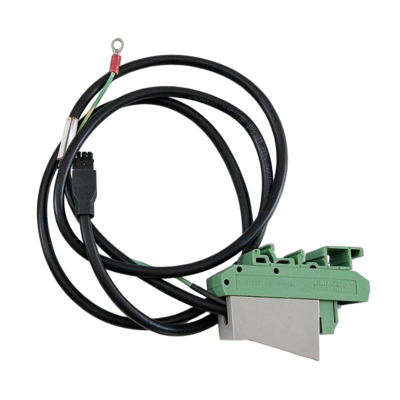
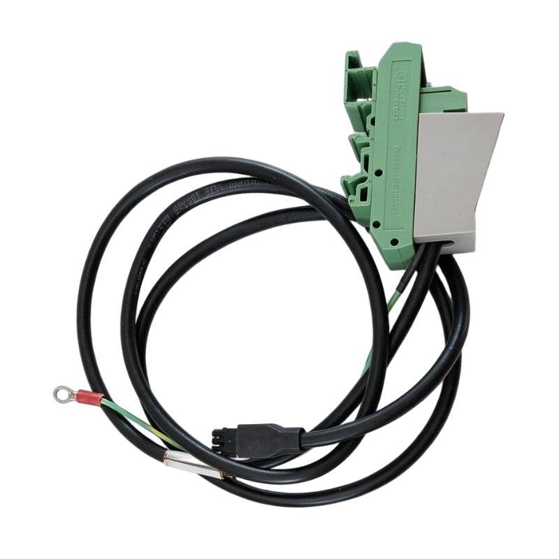
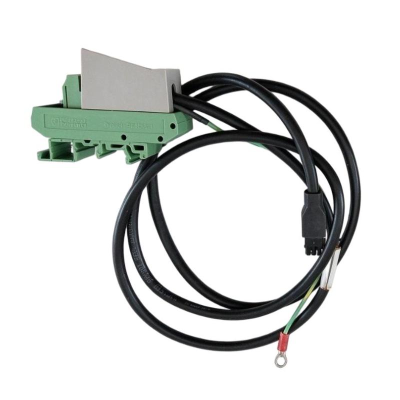
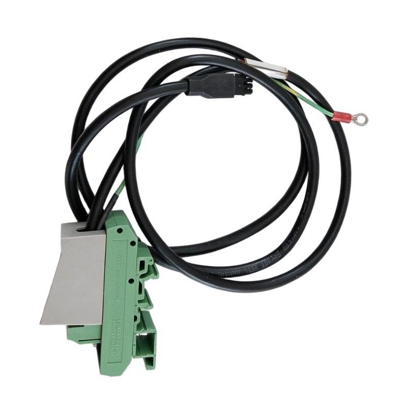
- Foxboro
- P0923DD
- Alarm Status Relay Output Cable
- USA
- 1.8 meters
- 3 kg
- Xiamen, China
- New & In Stock
- T/T, PayPal, Western Union
- 1 Year
- 1-3 Working Days
- DHL, UPS, TNT, FedEx and EMS.
- 24-Hour Service
- COO
- 8
Our advantage

Global Logistics
We have a 10-year logistics and express cooperation agreement, so our products can be shipped to any place in the world.

Brand new and original
Our products are imported in bulk from the place of origin. Because of the cooperative relationship, our products are all original and 100% new.

24-hour service
We provide 7*24 hours service to our customers. We will be there whenever you need us.

Price advantage
All our products are priced very favorably because we have our own warehouse and supply.
| Company Information | |||
| [email protected] | |||
| Mobile | +8615980777398 | ||
| +8615980777398 | |||
| 15980777398 |
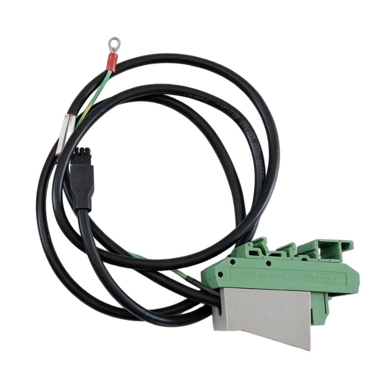
Product Overview
The Foxboro P0923DD Alarm Status Relay Output Cable is an industrial control accessory designed for alarm-status monitoring in Foxboro I/A Series control systems. It provides a physical connection between a power supply’s alarm-status relay output and an external indication or monitoring circuit.
In distributed control systems (DCS), monitoring the condition of power supplies is important for maintaining system availability. A power-related alarm can indicate that a supply is no longer operating within its normal condition, allowing operators or maintenance personnel to investigate before the problem affects connected control equipment.
The P0923DD is a 1.8-meter cable assembly intended for use with a Form C relay output. Its associated connection arrangement uses a DIN-rail-mounted terminal block, providing a practical interface for connecting relay contacts to external indicators or monitoring circuits.
Unlike a communication cable used to transfer network data, the P0923DD is designed for discrete relay-status signaling. Its purpose is to carry the electrical status of the associated alarm relay, not to provide Ethernet, fieldbus, or high-speed controller communication.
The cable length offers flexibility when arranging power supply equipment, terminal connections, and external indicators inside an industrial control cabinet. Proper installation helps maintain an organized wiring layout and makes alarm-status connections easier to inspect during routine maintenance.
For procurement and replacement, the complete part number should be checked carefully. Cable length, connector arrangement, terminal compatibility, and the relay interface must match the existing system. A cable with a similar appearance or length may not have the correct termination arrangement for the intended application.
Technical Specifications
| Parameter | Specification |
|---|---|
| Brand | Foxboro |
| Product Model | P0923DD |
| Product Type | Alarm Status Relay Output Cable |
| Product Family | Foxboro I/A Series |
| Application | Power supply alarm-status relay connection |
| Cable Length | 1.8 m (6 ft) |
| Relay Contact Type | SPDT, Form C |
| Relay Terminals | NC, NO, COM |
| Connection Arrangement | Relay output cable with terminal connection assembly |
| Terminal Mounting | DIN rail-mounted terminal block |
| Switching Current | Up to 2 A AC/DC, according to the associated relay specification |
| Maximum Current-Carrying Capacity | 3 A, according to the associated relay specification |
| Switching Power | 60 W / 125 VA, according to the associated relay specification |
| Dimensions | Not specified in the supplied product information |
| Shipping Weight Provided | 3 kg |
| Typical Application | External indication of power supply status |
Note: Electrical ratings above relate to the associated alarm-status relay specification, not to an independently verified rating for every cable conductor or installation. Confirm the connected relay, terminal block, and applicable documentation before wiring. The 3 kg figure is the supplied shipping weight and should be verified against the actual packed shipment.
Function and Working Principle
The P0923DD provides a connection path for the alarm-status relay output of compatible Foxboro power supply equipment. Its operation depends on the relay contacts and the electrical circuit connected to them.
1. Alarm Status Signal Connection
A control system’s power supply may provide a relay output to indicate whether its operating condition is normal or abnormal. The P0923DD connects this output to a suitable external circuit.
The external circuit may be connected to an indicator, monitoring input, or other compatible equipment. The exact destination depends on the installation design and the electrical characteristics of the connected device.
2. Form C Relay Interface
The associated relay uses a Form C contact arrangement, also known as a single-pole, double-throw (SPDT) configuration. It provides three terminals:
- COM: Common relay contact.
- NC: Normally closed contact.
- NO: Normally open contact.
The external circuit can use the appropriate contact pair to indicate a selected relay state. The contact arrangement allows the system designer to choose a suitable normally open or normally closed signaling method.
The actual contact state depends on the relay’s energized or de-energized condition. The wiring diagram and associated power supply documentation should be consulted before connecting the cable.
3. Power Supply Status Monitoring
In the associated Foxboro power supply documentation, the alarm relay changes state according to the supply’s status. The documented example identifies a de-energized relay with an alarm condition and an energized relay with a power-OK condition.
This arrangement allows external equipment to detect a change in supply status without requiring the monitoring circuit to interpret a digital communication protocol.
Correct circuit design is essential because the relay’s contact state must be interpreted in the context of the connected power supply and the chosen NC or NO terminal.
4. External Indication
The relay output can be connected to an appropriate external indicator or monitoring circuit. Depending on the application, this may allow a cabinet indicator, alarm panel, or compatible control-system input to respond when the monitored power supply changes state.
The P0923DD itself does not generate an alarm message or analyze process data. It provides the physical connection required to make the relay’s status available to the external circuit.
Role in Industrial Control Systems
The P0923DD supports power-status monitoring in industrial automation installations where reliable power is essential for control-system operation.
Foxboro I/A Series DCS Integration
The cable is associated with Foxboro I/A Series power supply hardware and its alarm-status relay output. It can be used where the relevant power supply configuration supports the specified cable and terminal arrangement.
When integrated correctly, the relay status can be made available to an external monitoring or indication circuit. This helps maintenance personnel identify power-related issues without relying exclusively on visual inspection of the power supply.
Alarm Panel Integration
An external alarm panel may use the relay signal to indicate a power supply condition. The cable provides the physical connection between the relay output and the relevant external circuit.
The indicator, input module, or alarm panel must be electrically compatible with the relay contact rating and the selected wiring method.
Control Cabinet Monitoring
Industrial cabinets may contain multiple power supplies and control-system components. Using a dedicated alarm-status connection can help organize the monitoring wiring and simplify maintenance.
The 1.8-meter length provides some flexibility in locating the terminal connection relative to the monitored power supply. Actual routing should avoid unnecessary cable tension, sharp bends, and interference with cabinet doors or moving equipment.
Maintenance and Troubleshooting
When a power-related alarm occurs, the relay output can help maintenance personnel distinguish a reported supply-status change from other control-system issues.
Troubleshooting should include checking the power supply itself, relay state, cable connections, external monitoring circuit, and relevant alarm logic. A fault indication should not automatically be attributed to the cable without checking the complete circuit.
Industrial Applications
1. Distributed Control Systems
Foxboro I/A Series installations use power supply and monitoring hardware to support distributed control functions. The P0923DD can connect an appropriate alarm-status relay output to an external monitoring circuit in a compatible configuration.
This is useful where maintenance teams need to monitor the condition of control-system power equipment.
2. Process Automation Plants
Chemical processing, refining, utilities, and other continuous-process facilities rely on stable power for their control equipment. An alarm-status connection can help provide an additional indication of power supply condition.
The cable does not provide power redundancy by itself. Any redundancy depends on the power supply architecture and the system design.
3. Industrial Control Cabinets
The P0923DD may be used in cabinets where power supply status is routed to terminal blocks, indicators, or monitoring equipment. Its specified 1.8-meter length supports installations where the destination is not immediately adjacent to the power supply.
Cable routing and terminal placement should be planned to maintain access for inspection and replacement.
4. Remote Alarm Indication
Where an external monitoring circuit is designed to receive relay contacts, the P0923DD can help make the power supply’s status available at the designated connection point.
The receiving equipment must support the signal type and electrical ratings. The cable should not be used as a substitute for a suitable communication interface where digital data transmission is required.
5. Industrial Equipment Maintenance
In existing installations, a matching replacement cable can help restore the intended alarm-status connection following damage, connector failure, or maintenance work.
Using the correct part number reduces the risk of mismatched connections and unnecessary changes to the established wiring arrangement.
Installation and System Integration
Correct installation helps preserve the reliability of the alarm-status circuit and reduces the possibility of incorrect status indications.
1. Verify the Part Number
Before installation, confirm that P0923DD is the required part for the installed Foxboro power supply or associated hardware. Check the connector arrangement, terminal configuration, and specified cable length.
Do not assume that all alarm-status cables are interchangeable merely because they use a similar connector or perform the same general function.
2. Check Cable Routing
The specified cable length is 1.8 meters. Plan the routing so that the cable reaches the required terminal location without excessive tension or unnecessary loops.
Avoid sharp bends, pinch points, hot surfaces, and locations where the cable could be damaged by cabinet doors or maintenance activities. Keep the wiring organized and separated from power conductors where required by the installation design.
3. Confirm Relay Terminal Assignments
Identify the NC, NO, and COM terminals from the relevant wiring diagram. Confirm which contact pair is required for the desired alarm logic.
Incorrect terminal selection can cause an external indicator to show the opposite state from the intended alarm condition. The expected behavior should be verified during commissioning.
4. Check Electrical Ratings
Verify the electrical ratings of the connected relay contacts and receiving circuit before wiring. The relay’s contact ratings do not mean that every connected monitoring device can accept the same voltage or current.
Use appropriate protective measures and wiring practices for the specific circuit. Follow the equipment manufacturer’s instructions and applicable electrical codes.
5. Install the Terminal Connection Assembly
Mount the associated terminal block securely on the designated DIN rail, where applicable. Ensure that the connection is mechanically stable and that wiring is clearly identified.
Keep terminal access unobstructed so that technicians can inspect and test the circuit without disturbing unrelated control wiring.
6. Test the Alarm Circuit
After installation, verify the relay’s normal and alarm states according to the power supply documentation. Confirm that the external indicator or monitoring input responds correctly to the intended contact state.
Testing should be conducted using the approved maintenance procedure. Do not interrupt a live control-system power supply simply to test the cable unless the system’s operating and safety procedures explicitly permit it.
Compatible System Components
The P0923DD should be used with equipment that supports its alarm-status relay interface and physical connection arrangement.
| Component | Function | Compatibility Considerations |
|---|---|---|
| Compatible Foxboro power supply | Provides the monitored power and relay-status output | Verify the exact power supply model and cable compatibility |
| Form C alarm-status relay | Provides NC, NO, and COM contact states | Confirm the relay’s contact ratings and state logic |
| DIN rail-mounted terminal block | Provides an organized termination point | Check the terminal assembly and mounting requirements |
| External indicator | Displays the monitored power status | Confirm input voltage, current, and wiring requirements |
| Alarm panel | Presents equipment status to operators | Verify the input circuit and alarm configuration |
| DCS or PLC input circuit | Receives a discrete status signal, where supported | Check input type, electrical isolation, and signal polarity |
| Control cabinet | Houses the power supply and associated connections | Provide adequate space, cable routing, and access |
| Terminal labels and wiring markers | Identify circuit connections | Maintain consistent labeling and documentation |
The listed components represent possible parts of a complete installation. They are not necessarily supplied with the P0923DD cable assembly.
Alternative Models and Replacement Considerations
When replacing the P0923DD, the primary requirement is to preserve the cable’s intended relay-status function and physical compatibility.
| Alternative or Related Part | Consideration |
|---|---|
| Foxboro P0923DB | A related alarm-status relay output cable with a shorter 1.2-meter length |
| Foxboro P0923DC | A related alarm-status relay output cable with a 1.5-meter length |
| Foxboro RH923DD | A newer catalog designation listed as superseding P0923DD in later Foxboro power supply documentation |
| Other Foxboro alarm-status cable assemblies | Must be checked for the correct power supply, connector arrangement, terminal interface, and cable length |
Do not select a replacement based only on cable length. Confirm the following details:
- Exact power supply or equipment model.
- Connector and terminal arrangement.
- Relay contact configuration.
- Cable length and routing requirements.
- Electrical ratings of the relay and receiving circuit.
- DIN rail terminal block requirements.
- Original and replacement part-number relationship.
- Condition, packaging, and supplier documentation.
A newer catalog number may be the designated successor, but compatibility should still be verified against the specific installed power supply and its documentation.
Key Advantages
Dedicated Alarm-Status Connection
The P0923DD provides a dedicated cable assembly for connecting a compatible alarm-status relay output to an external monitoring circuit.
1.8-Meter Cable Length
The 1.8-meter cable supports flexible positioning of the associated terminal connection within a suitable cabinet layout.
Form C Relay Interface
The associated SPDT relay arrangement provides NC, NO, and COM contacts, allowing the external circuit to use the appropriate contact state.
DIN Rail Terminal Integration
The terminal arrangement supports organized installation in industrial control cabinets and can simplify inspection of the alarm-status wiring.
Support for Maintenance Activities
A correctly installed alarm-status circuit helps maintenance personnel monitor the associated power supply condition and investigate abnormal indications.
Useful for Existing Foxboro Installations
The P0923DD can be relevant to maintenance and spare-parts procurement for compatible Foxboro I/A Series power supply installations.
Technical FAQs
1. What is the Foxboro P0923DD?
The Foxboro P0923DD is an alarm-status relay output cable with a specified length of 1.8 meters. It is designed to connect a compatible power supply relay output to an external indicator or monitoring circuit.
2. What is the cable length?
The specified length is 1.8 meters, equivalent to approximately 6 feet.
3. What does the P0923DD connect to?
It connects a compatible alarm-status relay output to an external circuit through the appropriate terminal connection arrangement. The exact power supply model and wiring should be confirmed before installation.
4. What does Form C mean?
Form C describes a changeover relay contact arrangement with common, normally open, and normally closed terminals. The receiving circuit uses the appropriate contact pair to detect the required relay state.
5. Can the P0923DD carry Ethernet or fieldbus data?
It is intended for discrete alarm-status relay signaling, not high-speed network communication. Use a suitable communication cable and interface for Ethernet or fieldbus applications.
6. Can it be used with any Foxboro power supply?
No. Compatibility depends on the power supply model, connector arrangement, and terminal interface. Check the equipment documentation before ordering.
7. Is the P0923DD the same as RH923DD?
Later Foxboro power supply documentation lists RH923DD as the successor to P0923DD. However, the correct replacement should be confirmed for the specific power supply and installation.
8. What is the shipping weight?
The supplied product information lists a shipping weight of 3 kg. Because this is relatively high for a 1.8-meter cable assembly, confirm the packaged weight with the supplier before calculating freight costs.
9. What should be checked when purchasing a replacement?
Verify the part number, cable length, connector condition, terminal arrangement, packaging, and compatibility with the installed power supply. For used or surplus stock, request clear photographs and confirm the item’s condition.
10. What should be checked if the alarm indication does not work?
Check the power supply’s status, relay state, NC/NO/COM wiring, terminal connections, and external monitoring circuit. Confirm the intended relay logic before replacing the cable.
Procurement and Maintenance Recommendations
When purchasing the Foxboro P0923DD, verify that the supplied cable matches the original part number and the intended power supply configuration. Confirm the 1.8-meter length, terminal connection arrangement, and any required DIN rail mounting hardware.
For industrial spare-parts procurement, request photographs of the cable assembly and connectors, along with confirmation of the item’s condition and any available product documentation. If the cable is being purchased for an existing installation, compare its connector and terminal arrangement with the installed assembly before dispatch.
The listed shipping weight of 3 kg should be checked against the actual packed shipment. This helps avoid inaccurate freight quotations and unnecessary shipping costs.
During maintenance, inspect the cable for damaged insulation, loose terminals, connector wear, or strain at the connection points. Ensure that the circuit labels and wiring diagrams are updated when the cable is replaced.
After replacement, test the alarm-status circuit using the approved procedure and confirm that the external monitoring device responds correctly to the relay state. Document the results so future troubleshooting can distinguish cable faults from power supply or monitoring-circuit problems.
Conclusion
The Foxboro P0923DD Alarm Status Relay Output Cable is a 1.8-meter cable assembly designed to connect a compatible Foxboro power supply alarm-status relay to an external indicator or monitoring circuit. Its Form C relay interface and DIN rail terminal arrangement support discrete status monitoring in suitable industrial control installations.
For maintenance and procurement, the most important considerations are the exact part number, connector and terminal compatibility, cable routing, and correct interpretation of the relay state. Verifying these details before installation helps maintain reliable alarm indication and supports effective troubleshooting in Foxboro I/A Series control systems.