

ProductPRODUCT
Featured products



Contact Us
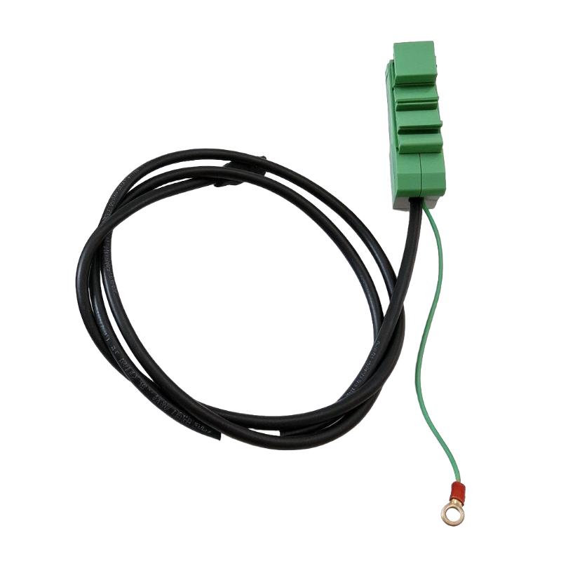
- Foxboro
- RH923DB
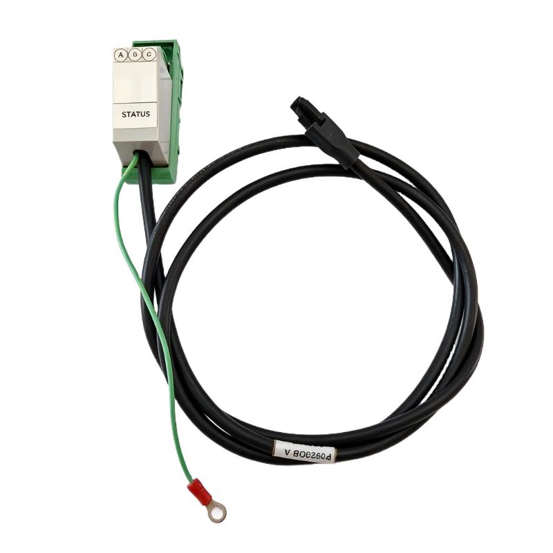
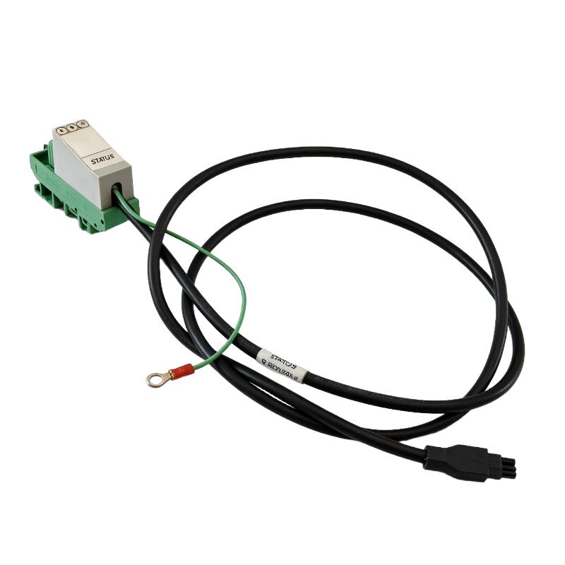
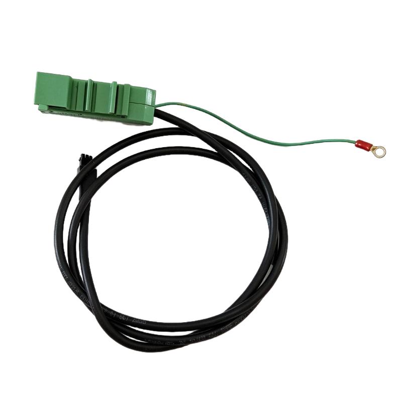
- Alarm Status Relay Output Cable
- USA
- 1.2 meters
- 3 kg.
- Xiamen, China
- New & In Stock
- T/T, PayPal, Western Union
- 1 Year
- 1-3 Working Days
- DHL, UPS, TNT, FedEx and EMS.
- 24-Hour Service
- COO
- 7
Our advantage

Global Logistics
We have a 10-year logistics and express cooperation agreement, so our products can be shipped to any place in the world.

Brand new and original
Our products are imported in bulk from the place of origin. Because of the cooperative relationship, our products are all original and 100% new.

24-hour service
We provide 7*24 hours service to our customers. We will be there whenever you need us.

Price advantage
All our products are priced very favorably because we have our own warehouse and supply.
| Company Information | |||
| [email protected] | |||
| Mobile | +8615980777398 | ||
| +8615980777398 | |||
| 15980777398 |
Product Overview
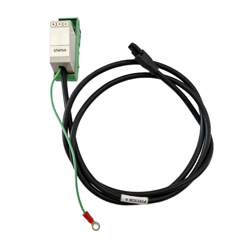
The Foxboro RH923DB Alarm Status Relay Output Cable is an industrial control accessory intended for connecting alarm-status relay signals to external indication or monitoring equipment. In distributed control system (DCS) installations, alarm-status interfaces help maintenance personnel and operators identify power-supply conditions and respond to abnormal operating states.
Foxboro control systems are used in process automation environments where equipment availability and dependable status monitoring are important. Within these systems, dedicated cables and termination accessories provide the physical connections needed to transfer electrical signals between control equipment, terminal assemblies, and external devices.
The RH923DB is listed with a cable length of 1.2 meters, making it suitable for applications where the connected equipment is installed relatively close to the relevant terminal or monitoring point. Its final suitability depends on the actual connector configuration, electrical interface, routing requirements, and compatibility with the installed Foxboro hardware.
An alarm status relay output cable is different from a standard communication cable. Its purpose is to carry relay-contact status signals rather than transmit a general-purpose data stream. The connected relay can provide an indication of whether a monitored power supply or related system is operating normally or has entered an alarm condition.
The cable can be relevant to maintenance, system refurbishment, and replacement projects involving legacy Foxboro control equipment. Before installation, engineers should verify the complete part number and compare the connector arrangement with the existing assembly. This is especially important because similar Foxboro part numbers may refer to different cable lengths, terminal arrangements, or equipment interfaces.
For procurement purposes, the supplied shipping weight is 3 kg. This figure should be treated as the listed shipping weight rather than the actual mass of the cable alone.
Technical Specifications
| Parameter | Specification |
|---|---|
| Brand | Foxboro |
| Product Model | RH923DB |
| Product Type | Alarm Status Relay Output Cable |
| Primary Function | Alarm and power-status relay signal connection |
| Cable Length | 1.2 m |
| Relay Interface Type | Alarm-status relay output |
| Typical Contact Arrangement | SPDT / Form C, subject to interface verification |
| Contact Terminals | NC, NO, COM, where applicable to the connected relay |
| Typical Installation | Industrial control cabinet or DCS equipment area |
| System Application | Foxboro industrial control and monitoring systems |
| Shipping Weight | 3 kg |
| Product Identification | Verify the exact RH923DB marking before ordering |
Note: The specifications above are based on the supplied product information and publicly documented characteristics of similar Foxboro alarm-status relay output cables. Exact RH923DB connector details and electrical ratings should be confirmed against the original product label and compatible equipment documentation.
Function and Working Principle
The primary function of an alarm-status relay output cable is to establish an electrical connection between a relay output and an external indication or monitoring circuit.
The cable itself does not generate alarm signals or make control decisions. Instead, it provides the physical signal path that allows the state of a relay to be communicated to another device.
1. Relay Status Signal Transmission
A relay changes its contact state in response to the condition monitored by its associated equipment. For example, a power-supply monitoring circuit may energize a relay when the supply is operating normally and de-energize it when an alarm condition occurs.
The output cable connects the relay interface to the appropriate external terminals. A connected indicator, monitoring circuit, or control-system input can then detect the resulting contact state.
The exact normal and alarm states depend on the connected relay design and the manufacturer’s interface specifications.
2. Form C Relay Contact Arrangement
Foxboro alarm-status relay interfaces of this type may use an SPDT Form C contact arrangement. This arrangement typically provides three terminals:
- COM (Common): The shared relay contact terminal.
- NO (Normally Open): The contact that is open when the relay is de-energized, assuming the standard contact definition.
- NC (Normally Closed): The contact that is closed when the relay is de-energized, assuming the standard contact definition.
When the relay changes state, the electrical connection between the common terminal and the other contacts changes accordingly.
The wiring design must follow the actual terminal identification. Engineers should not assume the relay’s energized state, alarm polarity, or contact assignment without checking the relevant equipment documentation.
3. External Alarm Indication
An external indicator or monitoring circuit can use the relay output to provide a visible or remotely monitored indication of equipment status.
Depending on the installation, the receiving device may be a panel indicator, a PLC digital input, a supervisory monitoring circuit, or another compatible alarm interface.
The RH923DB cable provides the connection path; the external equipment determines how the contact state is interpreted and displayed.
4. Electrical Signal Isolation
Relay contacts can provide a switching interface between a monitored status circuit and a separate external circuit, subject to the design of the connected equipment. This can simplify integration between different monitoring devices.
However, the cable itself does not guarantee galvanic isolation or protection against electrical faults. Isolation characteristics and permissible circuit voltages must be verified from the connected relay and system documentation.
Role in Industrial Control Systems
In a distributed control system, alarm and equipment-status signals help operators determine whether essential components are functioning correctly. Although an alarm-status cable is a relatively small accessory, its connection quality can affect the reliability of the associated indication circuit.
Power Supply Status Monitoring
Industrial control cabinets may contain power supplies that support controllers, I/O modules, communication equipment, and other system components. A relay output can provide an indication of the monitored supply’s condition.
The cable transfers this relay state to a suitable external monitoring circuit, allowing personnel to identify abnormal conditions without relying exclusively on local visual inspection.
DCS Alarm Integration
A DCS coordinates monitoring and control across process equipment. External alarm-status contacts may be incorporated into the broader monitoring arrangement where the system design supports such an interface.
The receiving device may be configured to recognize a contact transition and display an alarm or status message. Correct signal mapping, alarm logic, and wiring are required to ensure that the displayed status matches the actual equipment condition.
Maintenance and Troubleshooting
When a status indication is incorrect or unavailable, technicians may need to check the relay, wiring, connector, terminal assignments, and receiving circuit.
A correctly identified replacement cable can help restore the original signal path without requiring unnecessary changes to the control system.
Equipment Replacement
Legacy control installations often depend on exact cable assemblies and termination accessories. A replacement must match the original interface rather than merely having a similar length or appearance.
Verifying the part number, connector style, terminal arrangement, and cable routing requirements can reduce the risk of commissioning delays.
Industrial Applications
1. Foxboro DCS Control Cabinets
The cable may be used in compatible Foxboro control cabinet installations where an alarm-status relay output must be connected to an external indication or monitoring circuit.
Before use, confirm that the cable matches the relay interface fitted to the actual system.
2. Power Supply Monitoring
Power-supply monitoring is important in control systems because a supply fault can affect controller availability, I/O operation, or communication equipment.
Where supported by the installed hardware, a relay-status connection can provide a discrete indication of the monitored supply’s condition.
3. Process Automation Facilities
Industries such as chemical processing, oil and gas, power generation, water treatment, and manufacturing use industrial control systems to supervise equipment and process conditions.
A compatible alarm-status cable can support equipment-status monitoring within these environments. Its suitability depends on the specific Foxboro installation and the electrical characteristics of the receiving circuit.
4. Industrial Alarm Panels
Alarm panels can use relay contacts to indicate equipment states to operators or maintenance personnel. The cable may be used to connect a compatible relay output to the panel’s designated input terminals.
The receiving circuit must be designed for the relay’s contact rating and wiring arrangement.
5. Maintenance and Spare-Parts Replacement
For installed systems that have been operating for many years, replacement cables may be required because of connector damage, cable wear, cabinet modifications, or maintenance activities.
Using a verified compatible assembly helps preserve the original wiring arrangement and reduces the likelihood of introducing unintended signal changes.
Installation and System Integration
Correct installation is essential for dependable status monitoring. The cable must be compatible with the equipment interface, correctly routed, and securely connected.
1. Verify the Part Number
Check the full model marking before installation. Public listings may use different naming conventions for similar Foxboro cable assemblies, so the RH923DB designation should be verified against the original label or equipment documentation.
Do not substitute a cable solely because it has the same nominal length.
2. Inspect the Connectors
Before installation, inspect the connector body, pins or contacts, terminal block, and cable insulation. Look for bent contacts, contamination, corrosion, cracks, or evidence of mechanical damage.
A damaged connector may create intermittent contact and lead to unreliable alarm indications.
3. Confirm Terminal Assignments
Verify the relay’s common, normally open, and normally closed terminals where applicable. Compare the terminal assignments with the wiring diagram before connecting the external circuit.
Incorrect wiring can reverse the expected alarm logic or cause the monitoring circuit to report an incorrect status.
4. Route the Cable Correctly
Route the cable so that it is protected from sharp edges, excessive bending, crushing, and mechanical interference. Keep it separated from noisy power conductors where required by the installation design.
Observe the minimum bending radius and environmental limits specified for the actual cable assembly.
5. Check Electrical Ratings
Confirm the permitted voltage, switching current, contact rating, and receiving-circuit requirements. The electrical limits of the relay interface must not be exceeded.
Do not apply an external voltage to the cable terminals unless the connected interface documentation explicitly permits it.
6. Perform Functional Testing
After installation, test the status circuit using the approved commissioning procedure. Verify the normal-state indication and the alarm-state indication, where the system permits safe testing.
Confirm that the external indicator or monitoring system responds correctly to the relay transition. Record any wiring changes and restore the system to its intended operating state after testing.
Compatible System Components
The RH923DB should be selected as part of a complete alarm-status interface rather than as an isolated cable.
| Component | Function | Compatibility Considerations |
|---|---|---|
| Foxboro power supply or monitored equipment | Provides the status condition | Confirm the exact equipment model and relay interface |
| Alarm-status relay | Changes contact state according to the monitored condition | Verify contact arrangement and energized/de-energized logic |
| External indicator | Provides local visual status | Match the receiving circuit to the relay output |
| PLC digital input | Allows status monitoring by automation logic | Confirm input voltage, current, and contact-wiring requirements |
| DCS monitoring interface | Integrates status information into system supervision | Verify supported signal type and configuration |
| DIN-rail terminal block | Provides an organized termination point where applicable | Match the cable’s actual connector and terminal arrangement |
| Control cabinet | Houses the relay, terminals, and monitoring equipment | Ensure suitable cable routing and mechanical protection |
| Alarm annunciation system | Presents status information to operators | Configure correct alarm logic and response behavior |
The table describes possible components in an alarm-status installation. It does not confirm that every component is included with the RH923DB cable or that every listed interface is directly compatible.
Alternative Models and Replacement Considerations
When replacing the RH923DB, confirm the complete part number and interface details. Similar Foxboro cable assemblies may have different lengths or be intended for different power supplies, terminal blocks, or system configurations.
| Alternative or Related Model | Considerations |
|---|---|
| Foxboro P0923DB | A related 1.2 m alarm-status relay output cable found in product listings; verify whether it is the correct equivalent for the installed assembly |
| Foxboro P0923DC | A related cable assembly listed at 1.5 m; confirm connector and terminal compatibility |
| Foxboro P0923DD | A related cable assembly listed at 1.8 m; not automatically interchangeable with a 1.2 m version |
| Other Foxboro RH-series assemblies | May serve different interfaces or equipment generations; verify the exact application before substitution |
Before selecting a replacement, compare:
- Full catalog number and product label.
- Cable length and routing requirements.
- Connector type and pin or contact arrangement.
- Terminal block style and mounting method.
- Relay contact assignment.
- Permitted voltage and current.
- Compatibility with the monitored equipment.
- Compatibility with the external indicator or monitoring input.
A cable with the same length may still have a different connector or wiring assignment. The safest replacement is one confirmed against the original assembly documentation.
Key Advantages
Dedicated Status Signal Connection
A purpose-designed relay output cable provides the physical connection required to transmit a relay’s status to compatible monitoring equipment.
Support for External Indication
The cable can support local or remote status indication when connected to a correctly designed receiving circuit.
Practical Cabinet Integration
The listed 1.2 m length may suit installations where the relay interface and receiving terminals are positioned close together.
Maintenance Convenience
A compatible replacement cable can help restore an existing status-monitoring circuit without redesigning the entire interface.
Support for Legacy Control Systems
Dedicated cable assemblies remain relevant in older industrial installations where maintaining the original connector and wiring configuration is important.
Straightforward Troubleshooting
A clearly identified cable assembly helps technicians isolate wiring and connection problems during systematic fault diagnosis.
Technical FAQs
1. What is the Foxboro RH923DB?
The RH923DB is listed as an alarm status relay output cable for industrial control applications. It provides a physical connection between a relay-status interface and compatible external monitoring or indication equipment.
2. What is the cable length?
The supplied product information specifies a length of 1.2 meters. Verify the label on the actual assembly before installation or ordering.
3. What does an alarm-status relay output cable do?
It carries the electrical state of a relay contact to a compatible receiving circuit. The connected equipment can use that state to indicate whether a monitored condition is normal or requires attention.
4. Does the cable generate an alarm signal?
No. The cable provides the connection path. The monitored equipment and relay determine the contact state, while the external monitoring device interprets the signal.
5. Can it be connected to a PLC?
Potentially, if the relay output, cable termination, and PLC input are electrically compatible. Check the exact terminal assignments, input requirements, and relay ratings before connecting the cable.
6. Is RH923DB the same as P0923DB?
This equivalence has not been confirmed by reliable manufacturer documentation. P0923DB is listed as a related 1.2 m alarm-status relay output cable, but the complete part number and connector arrangement must be verified before treating it as a substitute.
7. What should be checked before installation?
Check the part number, connector condition, terminal assignment, cable routing, relay contact arrangement, and electrical ratings. Confirm that the receiving circuit is designed for the relay output.
8. What is the shipping weight?
The supplied listing specifies a shipping weight of 3 kg. This should not be interpreted as the net weight of the cable itself.
9. Can a longer cable be used instead?
A longer cable may be available in the same general product family, but it should not be assumed to be interchangeable. Confirm the connector, electrical interface, approved cable type, and routing requirements before substitution.
10. How can an alarm-status cable fault be diagnosed?
Follow the approved maintenance procedure to inspect the cable, connectors, relay contacts, terminal assignments, and receiving circuit. Verify continuity only after following the applicable isolation and safety procedures. Functional testing should confirm both normal and alarm indications where safely possible.
Procurement and Maintenance Recommendations
When purchasing the Foxboro RH923DB Alarm Status Relay Output Cable, begin by confirming the full model number on the installed cable or associated equipment documentation. This is particularly important because similar Foxboro part numbers may represent different cable lengths or connection arrangements.
Request photographs of both ends of the cable and any identification label. Compare the connector style, terminal arrangement, and physical configuration with the existing assembly. If the cable is intended for a legacy system, confirm compatibility with the installed power supply or relay interface before ordering.
For shipping and inventory management, retain the supplied 3 kg shipping-weight figure as a logistics value unless the supplier provides a verified net weight. Packaging dimensions and carrier weight calculations should be confirmed separately.
During maintenance, inspect the cable for insulation damage, connector wear, loose terminals, and mechanical stress. Maintain proper cable routing and avoid unnecessary tension on connectors. After replacement, verify that the external monitoring circuit correctly displays the expected normal and alarm states.
For critical control systems, keep the cable part number and wiring details in the maintenance records. Clear identification reduces the risk of installing an incompatible substitute during an urgent repair.
Conclusion
The Foxboro RH923DB Alarm Status Relay Output Cable is listed as a 1.2 m cable assembly intended for connecting an alarm-status relay output to compatible external indication or monitoring equipment. Such connections help support power-status supervision, alarm indication, and maintenance activities in industrial control systems.
Before procurement or installation, verify the exact RH923DB identification, connector arrangement, relay contact assignments, and electrical compatibility. Although P0923DB is a related 1.2 m cable listed for alarm-status relay applications, equivalence should not be assumed without confirmation. Accurate part identification and functional testing help preserve the reliability of the original monitoring circuit.