

ProductPRODUCT
Featured products
Contact Us
- Schneider
- XCC-1912PS10KN
- XCC Incremental Encoder
- France
- 90 mm
- 1.36 kg
- Xiamen, China
- New & In Stock
- T/T, PayPal, Western Union
- 1 Year
- 1-3 Working Days
- DHL, UPS, TNT, FedEx and EMS.
- 24-Hour Service
- COO
- 8
Our advantage

Global Logistics
We have a 10-year logistics and express cooperation agreement, so our products can be shipped to any place in the world.

Brand new and original
Our products are imported in bulk from the place of origin. Because of the cooperative relationship, our products are all original and 100% new.

24-hour service
We provide 7*24 hours service to our customers. We will be there whenever you need us.

Price advantage
All our products are priced very favorably because we have our own warehouse and supply.
| Company Information | |||
| [email protected] | |||
| Mobile | +8615980777398 | ||
| +8615980777398 | |||
| 15980777398 |
1. Product Overview
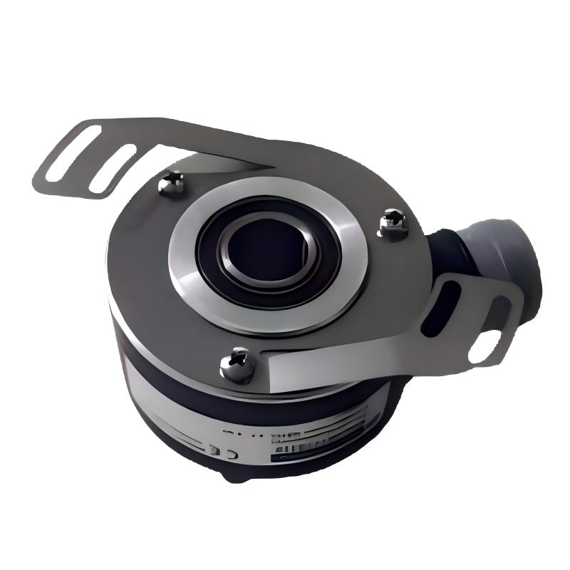
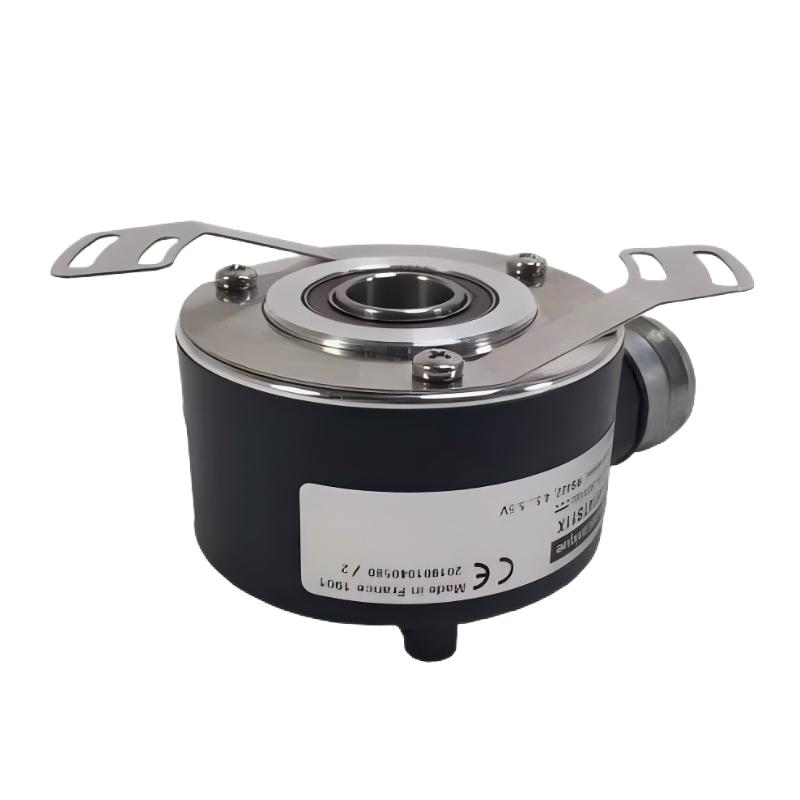
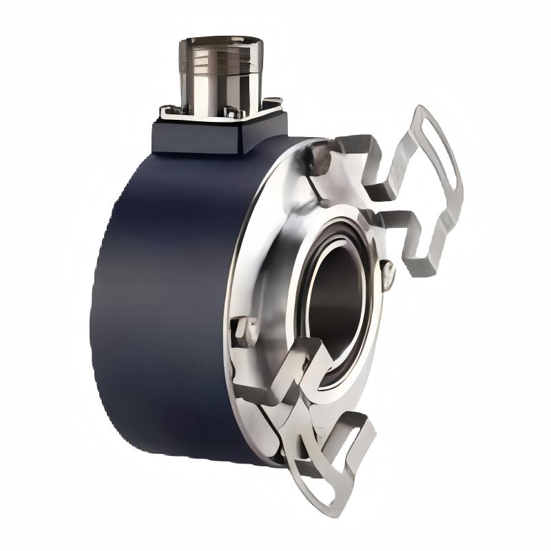
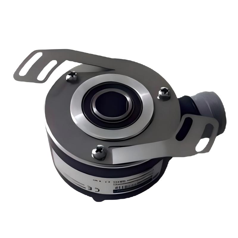
The Schneider Electric XCC1912PS10KN is an incremental rotary encoder designed for industrial automation systems that require reliable rotational feedback, speed measurement, and incremental position monitoring. Part of the OsiSense XCC encoder family, this model converts the rotation of a mechanical shaft into electrical pulse signals that can be processed by programmable logic controllers (PLCs), high-speed counters, motion controllers, and other compatible automation devices.
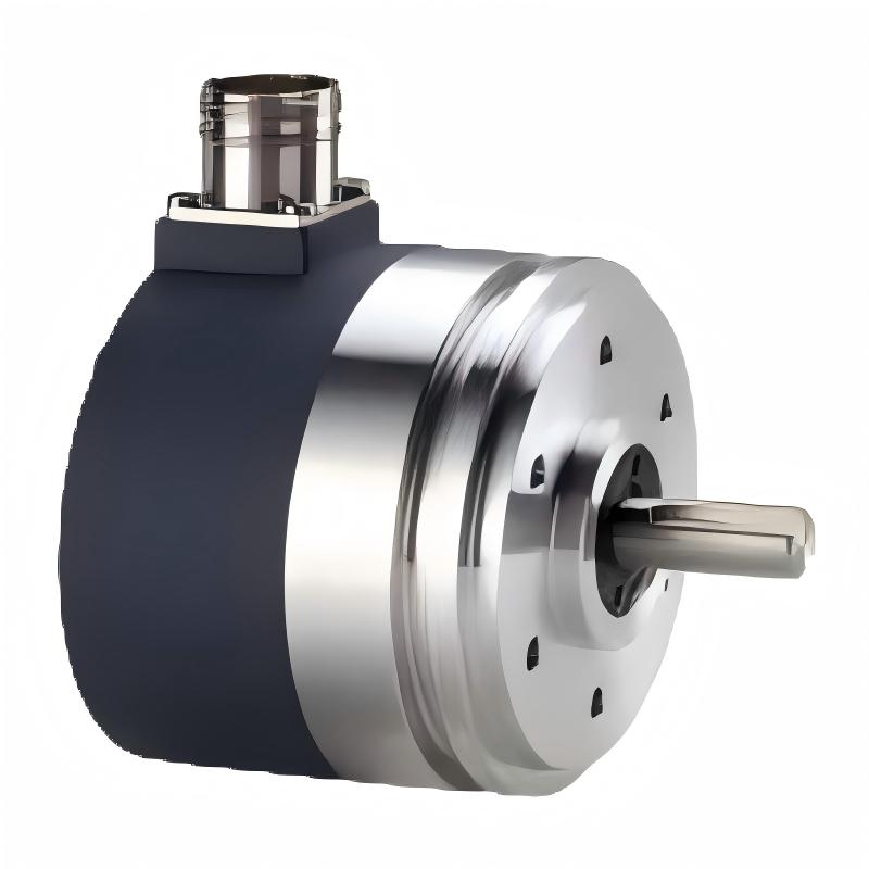
The XCC1912PS10KN features a 90 mm housing diameter and a 12 mm solid shaft. Its nominal resolution of 1000 points per revolution allows control equipment to monitor rotational movement and calculate shaft speed based on the frequency of the generated pulses. The encoder uses a Type K push-pull output stage and operates from an 11–30 V DC supply.
The model is designed with a radial M23 male connector, providing a defined electrical connection for compatible encoder cables and control-system interfaces. Its industrial construction supports integration into machinery that needs consistent rotational measurement during production and equipment operation.
Incremental encoders are commonly used in conveyor systems, packaging machinery, printing equipment, material handling systems, winding machines, and automated production lines. In these applications, the encoder supplies feedback signals that allow the control system to compare actual movement with expected operating conditions.
For industrial maintenance teams, automation engineers, and spare-parts procurement specialists, the Schneider XCC1912PS10KN is a potential replacement or installation option where its shaft dimensions, resolution, output type, and connector configuration match the application.
Before purchasing or installing the encoder, verify the full product reference and confirm compatibility with the receiving controller. The encoder’s resolution and electrical output must match the machine’s requirements to ensure reliable signal processing and correct movement calculations.
2. Technical Specifications
| Parameter | Specification |
|---|---|
| Brand | Schneider Electric |
| Product Series | OsiSense XCC |
| Model | XCC1912PS10KN |
| Product Type | Incremental Rotary Encoder |
| Housing Diameter | 90 mm |
| Shaft Type | Solid shaft |
| Shaft Diameter | 12 mm |
| Resolution | 1000 points per revolution |
| Output Stage | Type K |
| Output Type | Push-pull |
| Rated Supply Voltage | 11–30 V DC |
| Electrical Connection | Radial M23 male connector |
| Connector Configuration | 12-pin connector |
| Maximum Output Frequency | 100 kHz |
| Maximum Rotation Speed | Up to 6000 rpm for this 90 mm solid-shaft model family; confirm the exact variant documentation |
| Number of Channels | 3 |
| No-Load Current Consumption | 0–75 mA |
| Maximum Output Current | 40 mA |
| Protection Features | Short-circuit and reverse-polarity protection |
| Enclosure Material | Zamak |
| Shaft Material | Stainless steel |
| Weight | 1.36 kg |
| Typical Applications | Rotational measurement, speed monitoring, pulse counting, and machine automation |
Specifications should be verified against the nameplate and technical documentation for the exact model before installation or replacement.
3. Function and Working Principle
3.1 Converting Shaft Rotation into Electrical Signals
The XCC1912PS10KN is an incremental rotary encoder. Its primary function is to convert mechanical rotation into a sequence of electrical pulses that represent incremental movement.
When the encoder’s shaft rotates, its internal optical sensing system detects rotational movement and generates output signals. A connected PLC, counter, or motion controller processes the pulses to determine the amount of rotation.
By counting pulses over a defined interval, the controller can calculate rotational speed. By accumulating pulse counts, it can also track incremental movement from a known reference point.
This approach provides a practical feedback method for industrial equipment where rotational movement needs to be monitored or coordinated.
An incremental encoder does not inherently provide an absolute shaft position after power loss. If an application requires a known position following startup, the control system may need a homing procedure, a reference sensor, or another suitable position-establishing method.
3.2 Understanding the 1000-Point Resolution
The XCC1912PS10KN has a nominal resolution of 1000 points per revolution. This represents the encoder’s specified incremental resolution for one complete shaft rotation.
For example, 250 points correspond to one-quarter of a revolution under the nominal point-count convention. A controller can use the accumulated pulse count to calculate the rotational movement of the connected mechanism.
The effective count value in the control program depends on how the receiving device processes the signals. Some controllers count selected signal edges, while others use quadrature decoding or other processing modes. Engineers should distinguish the encoder’s nominal resolution from the final count value configured in the PLC.
The 1000-point resolution can be suitable for applications requiring more detailed rotational feedback than lower-resolution variants provide, without necessarily requiring a higher-resolution encoder.
3.3 Push-Pull Output Operation
The XCC1912PS10KN uses a Type K push-pull output stage. This output actively drives the signal toward its high and low states within its specified electrical limits.
Push-pull outputs can interface with compatible industrial inputs without requiring the same external signal arrangement used by some other output types. However, the receiving device must support the encoder’s voltage levels, signal characteristics, and current requirements.
Before connecting the encoder, confirm that the PLC input or high-speed counter is compatible with an 11–30 V DC push-pull encoder. A similar-looking encoder with an RS-422 output may require a different input interface and supply arrangement.
3.4 Rotational Speed Measurement
The pulse frequency generated by the encoder changes according to the shaft’s rotational speed. A compatible controller can measure the frequency and calculate speed based on the configured resolution.
This feedback can help a machine monitor conveyor speed, detect a stopped roller, compare actual movement against a target, or coordinate several sections of an automated production line.
The encoder supplies the measurement signals. Speed calculations, alarm thresholds, and machine-control responses are handled by the receiving automation equipment.
4. Role in Industrial Automation Systems
PLC-Based Position Monitoring
In PLC-based systems, the XCC1912PS10KN can provide incremental pulse feedback to a compatible high-speed counter or encoder input. The PLC can count these pulses to monitor rotation, estimate movement, or determine whether a mechanism has reached a programmed target.
Reliable operation depends on correct input configuration, suitable signal wiring, and sufficient controller counting frequency.
Motor-Driven Equipment Monitoring
When installed on a compatible mechanical shaft, the encoder can provide feedback about rotation generated by a motor-driven assembly. The control system can use the information to monitor speed, confirm movement, or identify unexpected changes in operation.
It should not automatically be treated as a replacement for a dedicated servo motor feedback device. Servo systems may require specific encoder protocols, electrical interfaces, resolutions, or safety-related features.
Conveyor and Production-Line Coordination
Industrial production lines often contain conveyors, rollers, feeders, and other moving mechanisms that need coordinated operation. An incremental encoder can provide pulse information to help a controller track rotation and monitor movement between process stages.
The effectiveness of synchronization depends on the controller program, mechanical coupling, signal-processing method, and timing requirements of the application.
Machine Diagnostics and Maintenance
Encoder feedback can help maintenance personnel identify abnormal operating conditions. For example, a controller may detect that the expected pulse signal has stopped while the machine is commanded to move.
The resulting alarm or stop response depends on the control program and the wider system design. An encoder provides movement feedback but does not independently diagnose every mechanical or electrical fault.
5. Industrial Applications
5.1 Conveyor Systems
Conveyor systems often require rotational feedback to monitor speed, confirm movement, and coordinate material transfer. The XCC1912PS10KN can be installed on a suitable rotating shaft when its mechanical and electrical characteristics match the application.
The PLC or counter can use the generated pulse signal to estimate rotational speed and monitor deviations from expected operating conditions.
5.2 Packaging Machinery
Packaging machinery may use incremental encoders for material feeding, roller movement, indexing, and coordinated machine cycles. The XCC1912PS10KN can provide pulse feedback for applications requiring a compatible 1000-point resolution and push-pull output.
The final suitability depends on the required measurement accuracy, mechanical arrangement, operating speed, and input capabilities of the receiving controller.
5.3 Printing and Converting Equipment
Printing and converting machinery often relies on synchronized roller movement and controlled material feeding. Encoder feedback can help the control system monitor rotation and compare actual movement with programmed process targets.
Correct installation and reliable signal transmission are important where the machinery operates continuously or requires coordination between multiple moving sections.
5.4 Material Handling Equipment
Material handling systems use conveyors, rollers, and rotating mechanisms to transfer goods through production and warehouse processes. Incremental feedback can support movement monitoring and speed supervision.
The encoder must be securely mounted, and the mechanical connection should avoid excessive shaft loading, vibration, or misalignment.
5.5 Winding and Feeding Systems
Winding and feeding machinery may require rotational measurement to monitor material movement and coordinate process stages. An encoder can supply pulse information that allows the controller to estimate rotation and adjust machine operation according to its programmed logic.
The resolution should be selected according to the required movement calculation and the characteristics of the mechanical transmission.
5.6 General Industrial Machinery
The XCC1912PS10KN may also be considered for suitable cutting machines, automated assembly equipment, industrial feeders, and other machinery that requires incremental rotational feedback.
Application suitability should always be determined by comparing the encoder’s specifications with the actual mechanical, electrical, and environmental requirements.
6. Installation and System Integration
6.1 Verify the Mechanical Arrangement
Before installation, confirm the 90 mm housing diameter, 12 mm solid-shaft dimensions, mounting arrangement, and available clearance.
The encoder must be mounted according to the equipment manufacturer’s instructions. The shaft coupling and mounting structure should minimize misalignment and avoid excessive radial or axial loading.
Incorrect installation can increase mechanical stress, affect measurement reliability, or shorten the service life of the encoder. Check the mounting dimensions and mechanical load limits before commissioning.
6.2 Confirm the DC Supply
The XCC1912PS10KN uses an 11–30 V DC supply. Verify that the available power source remains within this range under normal operating conditions and that the polarity is correct.
Do not assume that all XCC encoder variants use the same supply voltage. Related models with RS-422 outputs may use a different supply range and require a different electrical interface.
6.3 Check the M23 Connector
This model uses a radial M23 male connector with a 12-pin configuration. Ensure that the mating cable or connector assembly is suitable for the exact encoder variant.
Confirm the pin assignment using the applicable wiring documentation before applying power. Do not rely solely on wire colours or the pin layout of another encoder model.
6.4 Match the Output to the Controller
The encoder’s Type K push-pull output must be compatible with the receiving PLC, high-speed counter, or motion controller.
Check the input voltage range, maximum pulse frequency, current requirements, and signal-processing method. The controller must be capable of processing the generated signal at the machine’s maximum operating speed.
6.5 Configure the Pulse-Counting Function
Configure the controller for the appropriate encoder input mode and counting method. Verify the expected count value per revolution and establish the required scaling for the connected mechanical mechanism.
If the application requires direction detection or a known starting position, confirm that the selected interface and control program support these functions.
6.6 Perform a Controlled Commissioning Test
After completing the wiring and mounting, test the encoder at a safe operating speed. Confirm that the controller receives stable pulses and that the measured count and speed correspond to the expected mechanical movement.
Check for missing pulses, incorrect scaling, unstable readings, and unexpected movement before returning the equipment to normal production.
7. Compatible System Components
The XCC1912PS10KN operates as part of a broader automation system. The following component categories may be suitable when their technical characteristics are compatible.
| Component Category | Function | Compatibility Considerations |
|---|---|---|
| PLC with High-Speed Counter | Counts encoder pulses and processes movement data | Must support the Type K push-pull output and required pulse frequency |
| Dedicated Counter Module | Measures pulse counts or frequency | Confirm supported input voltage and signal type |
| Motion Controller | Processes rotational feedback for machine control | Verify supported encoder interface and resolution settings |
| Industrial DC Power Supply | Provides encoder operating power | Must supply a compatible 11–30 V DC output |
| M23 Encoder Cable | Connects the encoder to the control system | Confirm 12-pin connector compatibility and correct pin assignment |
| Signal Interface Module | Interfaces encoder signals with control equipment | Check electrical ratings and signal conditioning requirements |
| Mechanical Coupling | Connects the encoder shaft to the rotating assembly | Must suit the 12 mm solid shaft and mounting arrangement |
| Encoder Mounting Hardware | Secures the encoder to the machine | Confirm dimensions, alignment, and mechanical load limits |
These categories describe typical system components rather than guaranteed compatibility with every product. Verify the complete system configuration before ordering or installation.
8. Alternative Models and Replacement Considerations
Choosing an alternative encoder requires more than matching the housing diameter. Resolution, shaft size, output stage, supply voltage, connector configuration, and controller compatibility should all be considered.
| Model | Resolution | Output Type | Key Considerations |
|---|---|---|---|
| Schneider XCC1912PS01KN | 100 points/revolution | Push-pull, 11–30 V DC | Lower resolution than the XCC1912PS10KN |
| Schneider XCC1912PS03KN | 360 points/revolution | Push-pull, 11–30 V DC | Different resolution; controller scaling may need adjustment |
| Schneider XCC1912PS05KN | 500 points/revolution | Push-pull, 11–30 V DC | Lower resolution than the 1000-point model |
| Schneider XCC1912PS10KN | 1000 points/revolution | Push-pull, 11–30 V DC | Original model reference |
| Schneider XCC1912PS11KN | 1024 points/revolution | Push-pull, 11–30 V DC | Similar but different resolution |
| Schneider XCC1912PS10RN | 1000 points/revolution | RS-422, 5 V class | Different electrical interface and supply requirements |
These are related models in the same general 90 mm solid-shaft encoder family, but they are not automatically interchangeable.
The XCC1912PS11KN provides 1024 points per revolution rather than 1000. This difference can affect position scaling and speed calculations. The XCC1912PS10RN uses an RS-422 output interface and a different supply range, so it should not be treated as a direct replacement for the Type K push-pull version without confirming the receiving controller and wiring.
For a replacement project, using the same model is generally the simplest option when the original specification remains suitable and the product is available. If a substitute is necessary, verify its mechanical dimensions, electrical interface, resolution, connector, and configuration requirements.
9. Key Advantages of the Schneider XCC1912PS10KN
90 mm Industrial Housing
The 90 mm housing is part of the XCC encoder family designed for industrial rotational measurement applications. Its mechanical arrangement should be matched to the mounting space and shaft connection of the target machine.
12 mm Solid Shaft
The 12 mm solid shaft provides a defined mechanical interface for compatible couplings and rotating assemblies. Correct alignment and suitable mounting hardware are important for reliable operation.
1000-Point Resolution
The 1000-point resolution supports incremental rotational measurement and pulse-based movement calculations. It can suit applications requiring more detailed feedback than lower-resolution encoder variants.
Push-Pull Output Interface
The Type K push-pull output provides an active signal interface for compatible industrial controllers. Confirming the receiving input’s voltage and current characteristics helps ensure reliable pulse processing.
11–30 V DC Supply
The specified DC supply range supports integration into compatible industrial control systems. Correct supply polarity and stable power are essential for dependable operation.
Radial M23 Connector
The radial 12-pin M23 male connector provides a defined connection arrangement for suitable encoder cables. Correct cable selection and pin assignment help simplify integration and maintenance.
Broad Industrial Applications
The encoder can support rotational measurement, speed monitoring, pulse counting, and movement feedback in suitable conveyor, packaging, printing, winding, and material handling applications.
10. Technical FAQs
Q1: What is the Schneider XCC1912PS10KN?
The Schneider Electric XCC1912PS10KN is an OsiSense XCC incremental rotary encoder designed to convert shaft rotation into electrical pulse signals for industrial automation systems.
Q2: What is the diameter of the XCC1912PS10KN?
The encoder has a housing diameter of 90 mm and a 12 mm solid shaft.
Q3: What is its resolution?
The XCC1912PS10KN has a nominal resolution of 1000 points per revolution. The effective count value used by a controller depends on its signal-decoding and counting configuration.
Q4: What supply voltage does it require?
The specified supply voltage range is 11–30 V DC. Confirm the correct polarity and electrical interface before connecting the encoder.
Q5: What output type does it use?
It uses a Type K push-pull output stage. The connected PLC input or counter must support this electrical interface.
Q6: What connector does it use?
The model uses a radial M23 male connector with a 12-pin configuration. Confirm the mating cable and pin assignment against the correct wiring documentation.
Q7: Can it connect directly to any PLC?
No. The PLC or counter must support the encoder’s push-pull output, required voltage levels, and pulse frequency. A compatible high-speed counter or encoder input may be required.
Q8: Can the XCC1912PS11KN replace the XCC1912PS10KN?
Not automatically. The XCC1912PS11KN has a resolution of 1024 points per revolution, compared with 1000 points for the XCC1912PS10KN. This difference may affect count scaling and movement calculations. Confirm the control program and machine requirements before substitution.
Q9: Can the RS-422 version be used instead?
The XCC1912PS10RN is a related 1000-point encoder, but its RS-422 output interface and supply requirements differ from the Type K push-pull version. It should only be considered after verifying the receiving controller, wiring, and electrical requirements.
Q10: Is it suitable for speed monitoring?
Yes, it can provide pulse signals for speed measurement when connected to a compatible controller. The controller calculates speed from the pulse frequency and configured resolution.
Q11: What should be checked before purchasing a replacement?
Verify the full part number, housing diameter, shaft diameter, resolution, output type, supply voltage, M23 connector configuration, and controller compatibility. Also confirm the mounting arrangement and required operating speed.
11. Procurement and Maintenance Recommendations
When sourcing the Schneider XCC1912PS10KN, check the complete model reference on the product label. Related XCC encoders may have similar housings while differing in resolution, output type, or supply voltage.
For replacement projects, compare the existing encoder’s mechanical and electrical specifications with those of the proposed unit. Particular attention should be paid to the difference between Type K push-pull and Type R RS-422 output variants, as well as differences in resolution.
During routine maintenance, inspect the encoder mounting, shaft coupling, connector condition, cable assembly, and surrounding mechanical components. Unexpected pulse loss or unstable measurements may result from electrical interference, wiring problems, mechanical misalignment, or incorrect controller settings.
Before removing or installing an encoder, isolate the equipment according to the site’s safety procedures. After installation, verify the pulse count, speed calculation, and any required direction or reference-position functions.
For industrial spare-parts procurement, confirm stock status, product condition, warranty terms, and connector compatibility with the supplier. If the original model is unavailable, choose an alternative only after confirming electrical, mechanical, and functional suitability.
12. Conclusion
The Schneider Electric XCC1912PS10KN is a 90 mm incremental rotary encoder featuring a 12 mm solid shaft, 1000 points per revolution, a Type K push-pull output, and an 11–30 V DC supply range. Its radial M23 male connector provides a defined electrical interface for compatible industrial automation systems.
The encoder can support rotational measurement, speed monitoring, pulse counting, and movement feedback when integrated with a suitable PLC, high-speed counter, or motion controller. Correct mounting, compatible wiring, and appropriate controller configuration are essential for dependable performance.
For maintenance teams, system integrators, and industrial equipment buyers, verifying the complete model reference and electrical interface is an important step when purchasing or replacing the XCC1912PS10KN. Careful specification checking helps reduce installation errors and supports reliable operation in industrial automation applications.