

ProductPRODUCT
Featured products
Contact Us
- Schneider
- XCC-1406TR10K
- XCC Incremental Encoder
- France
- 40 mm
- 0.405 kg
- Xiamen, China
- New & In Stock
- T/T, PayPal, Western Union
- 1 Year
- 1-3 Working Days
- DHL, UPS, TNT, FedEx and EMS.
- 24-Hour Service
- COO
- 8
Our advantage

Global Logistics
We have a 10-year logistics and express cooperation agreement, so our products can be shipped to any place in the world.

Brand new and original
Our products are imported in bulk from the place of origin. Because of the cooperative relationship, our products are all original and 100% new.

24-hour service
We provide 7*24 hours service to our customers. We will be there whenever you need us.

Price advantage
All our products are priced very favorably because we have our own warehouse and supply.
| Company Information | |||
| [email protected] | |||
| Mobile | +8615980777398 | ||
| +8615980777398 | |||
| 15980777398 |
1. Product Overview
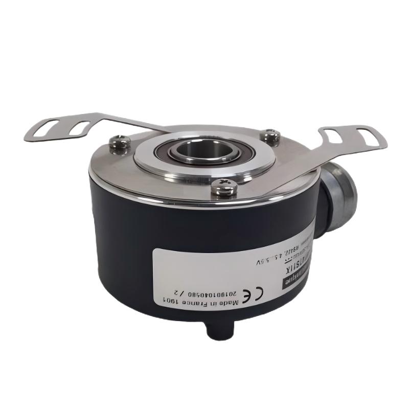
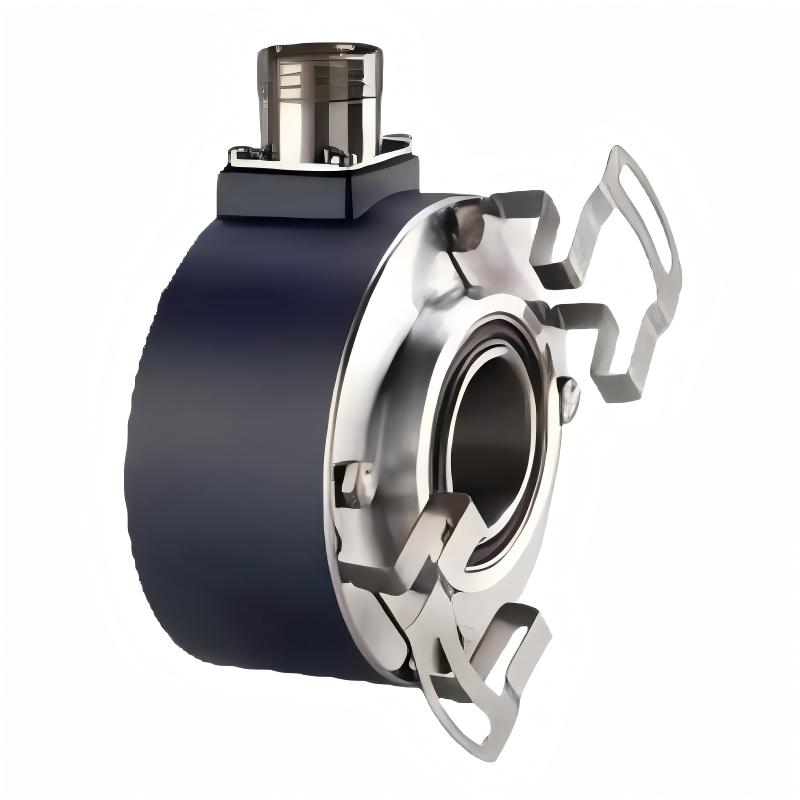
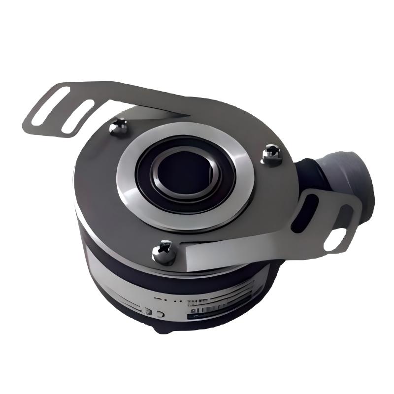
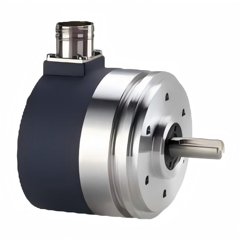
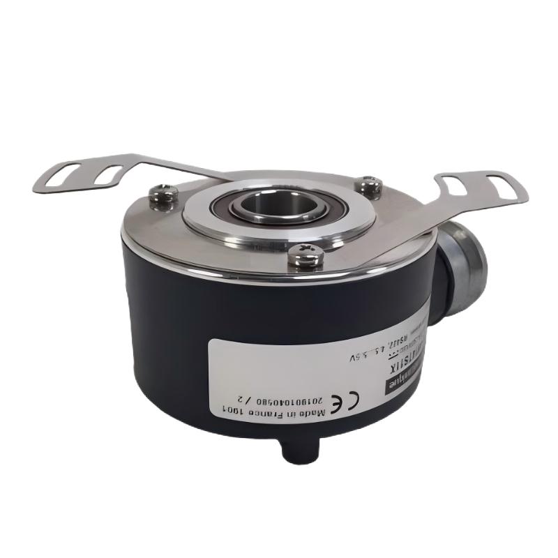
The Schneider Electric XCC1406TR10K is an incremental rotary encoder designed to provide rotational position, speed, and pulse-counting feedback for industrial automation equipment. As part of the Schneider Electric OsiSense XCC encoder family, it is intended for applications where reliable motion feedback is required for machine control, production monitoring, and automated positioning.
With a 40 mm housing diameter, a 6 mm through shaft, and a rated resolution of 1000 points per revolution, the XCC1406TR10K can convert mechanical rotation into electrical pulse signals that can be processed by PLCs, counters, motion controllers, and other compatible automation devices.
The encoder uses a push-pull output stage and operates with a DC supply voltage of 11–30 V. Its radial shielded cable connection supports integration into industrial control systems, while its compact cylindrical construction makes it suitable for a range of machinery and motion-control installations.
The XCC1406TR10K is particularly relevant to applications involving conveyor systems, packaging machinery, material handling equipment, printing machinery, and industrial production lines. By supplying feedback signals corresponding to shaft rotation, it helps control systems monitor movement and coordinate machine operations.
For equipment maintenance teams, system integrators, and industrial spare-parts buyers, the Schneider XCC1406TR10K provides an encoder option for systems designed around its mechanical dimensions, electrical interface, and feedback resolution. Before ordering a replacement, users should confirm the complete model reference and verify that the existing controller supports the encoder’s output type and electrical characteristics.
2. Technical Specifications
| Parameter | Specification |
|---|---|
| Brand | Schneider Electric |
| Product Series | OsiSense XCC |
| Model | XCC1406TR10K |
| Product Type | Incremental Rotary Encoder |
| Housing Diameter | 40 mm |
| Shaft Type | Through shaft |
| Shaft Diameter | 6 mm |
| Resolution | 1000 points per revolution |
| Output Stage | Type K, push-pull |
| Rated Supply Voltage | 11–30 V DC |
| Electrical Connection | Radial shielded cable |
| Cable Length | 2 m |
| Cable Composition | 8 × 0.14 mm² |
| Number of Channels | 3 |
| Maximum Output Frequency | 100 kHz |
| Maximum Rotation Speed | 9000 rpm |
| Maximum Output Current | 40 mA |
| No-Load Current Consumption | 0–75 mA |
| Protection | Short-circuit and reverse-polarity protection |
| Enclosure Materials | Aluminium and Zamak |
| Weight | 0.405 kg |
| Typical Applications | Speed monitoring, position feedback, pulse counting, and machine automation |
Specifications should be checked against the encoder’s nameplate and the documentation for the exact installed variant before commissioning or replacement.
3. Function and Working Principle
3.1 Converting Rotation into Electrical Signals
An incremental encoder measures rotational movement by generating electrical pulses as its shaft rotates. The XCC1406TR10K uses an optical sensing principle to detect rotational movement and generate corresponding output signals.
When the connected machine shaft turns, the encoder produces a pulse sequence. The receiving controller counts these pulses to determine how far the shaft has rotated. By measuring the pulse frequency over time, the controller can also calculate rotational speed.
Unlike an absolute encoder, an incremental encoder does not inherently retain the complete absolute shaft position after power is removed. In applications that require a known starting position, the machine may need a homing procedure or another reference mechanism.
3.2 Resolution and Pulse Counting
The XCC1406TR10K has a nominal resolution of 1000 points per revolution. This means that the encoder produces a specified number of incremental measurement points for each complete shaft rotation.
For example, if a controller counts 500 points against a 1000-point-per-revolution reference, the corresponding fraction of a revolution is approximately one-half, subject to the controller’s counting convention and signal-processing method.
Actual position calculation depends on how the receiving device interprets the encoder signals. Some controllers count selected signal edges, while others use quadrature decoding or different counting modes. Therefore, the encoder’s nominal resolution should not be confused with the final system’s configured count value.
3.3 Push-Pull Output
The XCC1406TR10K uses a Type K push-pull output stage. This output arrangement actively drives the signal toward both the high and low logic states, subject to the specified electrical limits.
The push-pull interface can simplify signal transmission to compatible industrial controllers and counting devices. However, the receiving input must be compatible with the encoder’s 11–30 V DC supply range and its output voltage and current characteristics.
Users should not assume that every PLC high-speed counter or encoder input supports the same electrical interface. Checking input specifications before installation helps prevent unreliable counting and potential electrical damage.
3.4 Speed Feedback
The frequency of the generated pulse train changes with shaft speed. A PLC, counter, or motion controller can measure this frequency and calculate rotational speed using the encoder’s configured resolution.
This feedback can be used to monitor conveyor speed, verify motor-driven movement, detect speed deviations, or coordinate multiple machine sections.
The encoder itself provides measurement signals; the receiving control system performs the calculations, comparisons, and control actions.
4. Role in Industrial Automation Systems
PLC-Based Position Monitoring
In PLC-controlled machinery, the XCC1406TR10K can provide incremental movement feedback to a compatible high-speed counter or encoder input. The controller can use accumulated counts to monitor travel distance, rotational position, or the progress of a machine cycle.
For applications requiring accurate pulse counting, the PLC input frequency limit, counting mode, and electrical interface must all be suitable for the encoder.
Motor and Drive Feedback Applications
The encoder can be used in suitable systems to monitor the rotation of a motor-driven shaft or mechanical assembly. Its signals may support speed supervision, movement verification, and process coordination.
It should not automatically be considered a direct replacement for a motor’s dedicated feedback encoder. Servo drives and closed-loop motor systems may require specific feedback protocols, resolutions, connector arrangements, or safety certifications.
Production Line Synchronization
In automated production lines, motion feedback can help a controller coordinate conveyors, rollers, feeders, cutting equipment, and other moving components. Encoder pulse counts provide a measurable representation of movement that can be compared with process targets.
The effectiveness of synchronization depends on the controller program, mechanical arrangement, signal-processing capability, and timing requirements of the application.
Equipment Monitoring and Troubleshooting
Incremental feedback can also help maintenance personnel identify unexpected machine behavior. For example, the controller may detect that a shaft has stopped producing pulses even though a movement command remains active.
Such detection requires suitable control logic and does not mean the encoder independently diagnoses every mechanical or electrical fault.
5. Industrial Applications
5.1 Conveyor Systems
Conveyor equipment often requires movement monitoring to maintain production flow and identify unexpected stoppages. The XCC1406TR10K can provide pulse feedback when installed on a compatible rotating shaft or measuring mechanism.
The controller can use this information to estimate rotational speed, monitor movement, and coordinate related equipment.
5.2 Packaging Machinery
Packaging lines may use rotary feedback for film feeding, roller movement, indexing, and product positioning. An incremental encoder can provide the pulse signals required for counting and motion monitoring.
The suitability of the XCC1406TR10K depends on the machine’s required resolution, mechanical mounting, operating speed, and controller input specifications.
5.3 Printing and Converting Equipment
Printing and converting machinery may require synchronized movement between rollers, feed mechanisms, and processing stations. Encoder feedback can help the control system monitor shaft rotation and identify deviations from expected movement.
Correct installation and stable signal transmission are important in applications involving continuous motion and changing operating speeds.
5.4 Material Handling Systems
Automated material handling equipment can use incremental encoders to monitor the rotation of rollers, feed mechanisms, and other moving assemblies. The resulting feedback can support counting, speed monitoring, and movement coordination.
The encoder must be mounted securely, and the mechanical coupling must avoid excessive axial or radial loading.
5.5 General Industrial Machinery
Other potential applications include winding equipment, feeders, cutting machines, automated assembly equipment, and machinery requiring rotational feedback. The final selection should be based on the actual mechanical and electrical requirements rather than the encoder family name alone.
6. Installation and System Integration
6.1 Verify Mechanical Compatibility
Before installation, confirm the encoder’s 40 mm housing diameter, 6 mm through-shaft configuration, mounting arrangement, and available installation space.
The through shaft must align correctly with the associated rotating assembly. Poor alignment, excessive shaft loading, or an unsuitable coupling can shorten bearing life and affect measurement reliability.
Follow the equipment manufacturer’s mounting instructions and do not apply loads beyond the encoder’s documented limits.
6.2 Confirm the Power Supply
The specified supply range for the XCC1406TR10K is 11–30 V DC. Confirm that the available supply remains within this range under normal operating conditions and that the polarity is correct.
The supply should be appropriate for the encoder and the surrounding electrical environment. Avoid connecting the encoder to an incompatible voltage source or assuming that every encoder in the XCC family uses the same supply voltage.
6.3 Check the Output Interface
The encoder’s Type K push-pull output must be compatible with the receiving device. Check the PLC input or counter module’s supported voltage levels, input current, maximum pulse frequency, and signal interpretation.
The specified maximum output frequency is 100 kHz. The complete system must be configured so that the controller can reliably process the pulse frequency generated at the application’s operating speed.
6.4 Route and Protect the Cable
The XCC1406TR10K uses a radial shielded cable with a specified length of 2 m. Route the cable to minimize exposure to electrical noise from motor cables, variable frequency drives, contactors, and other high-interference sources.
Where required, follow the equipment manufacturer’s shielding and grounding recommendations. Avoid sharp bends, crushing, excessive tension, and contact with hot or moving machinery.
6.5 Configure the Controller
After wiring, configure the PLC, counter, or motion controller for the correct input mode and counting method. Verify the expected counts per revolution and determine whether the application requires direction detection, speed calculation, or a homing procedure.
Conduct an initial functional test at a safe operating speed. Compare the controller’s measured counts and speed with the expected mechanical movement before returning the machine to normal operation.
7. Compatible System Components
The XCC1406TR10K is designed to work as part of a broader automation system. The following component categories may be suitable when their electrical and functional specifications are compatible.
| Component Category | Role in the System | Compatibility Considerations |
|---|---|---|
| PLC with High-Speed Counter | Counts encoder pulses and processes movement data | Verify voltage levels, counting frequency, and input mode |
| Dedicated Counter Module | Measures pulse counts or frequency | Confirm support for push-pull signals |
| Motion Controller | Uses feedback for machine movement monitoring | Check supported encoder interfaces and resolution settings |
| DC Power Supply | Provides encoder operating power | Must provide a compatible 11–30 V DC supply |
| Signal Interface Module | Connects field signals to control equipment | Verify electrical ratings and signal conditioning requirements |
| Industrial Cable Accessories | Support cable routing and protection | Match the installation environment and wiring requirements |
| Mechanical Coupling or Mounting Hardware | Connects the encoder to the rotating assembly | Confirm shaft diameter, alignment, and loading limits |
The table describes component categories rather than guaranteed model-specific compatibility. The correct interface must be confirmed using the technical documentation for the complete control system.
8. Recommended Alternative Models and Replacement Considerations
Selecting an alternative encoder requires more than matching the housing diameter. Resolution, output type, supply voltage, shaft configuration, cable arrangement, and controller compatibility must all be considered.
| Model or Option | Main Difference | Important Consideration |
|---|---|---|
| Schneider XCC1406TR01K | 100 points per revolution, Type K output | Lower resolution; not a direct functional equivalent where 1000 points are required |
| Schneider XCC1406TR03K | 360 points per revolution, Type K output | Check required counting accuracy and controller configuration |
| Schneider XCC1406TR05K | 500 points per revolution, Type K output | Resolution differs from the XCC1406TR10K |
| Schneider XCC1406TR11K | 1024 points per revolution, Type K output | Similar resolution, but the exact count configuration must be checked |
| Schneider XCC1406TR10R | 1000 points per revolution, RS-422 output | Different electrical interface and supply requirements; not a plug-and-play substitute |
These models belong to the same general XCC encoder family, but they are not automatically interchangeable. The Type K and Type R output variants have different electrical interfaces. Before choosing a replacement, confirm the original encoder’s full part number, controller input type, resolution requirements, and wiring.
For an existing installation designed specifically for the XCC1406TR10K, the same model is generally the most straightforward option when it remains available and its specifications meet the application’s requirements.
9. Key Advantages of the Schneider XCC1406TR10K
Compact 40 mm Housing
The 40 mm housing supports installation in machinery where available mounting space is limited. The through-shaft design is suited to applications designed around this mechanical arrangement.
1000-Point Resolution
The 1000-point specification provides incremental feedback for applications that need more detailed rotational measurement than lower-resolution variants offer.
Push-Pull Signal Output
The Type K push-pull output provides an active high and low signal interface for compatible industrial inputs. Correct electrical matching remains essential.
Broad DC Supply Range
The 11–30 V DC operating supply range can accommodate suitable industrial DC power arrangements within the documented limits.
Industrial Automation Applications
The encoder can support pulse counting, movement monitoring, speed measurement, and machine synchronization when integrated with suitable control equipment.
Defined Mechanical and Electrical Specifications
The specified shaft size, cable configuration, output frequency, and supply range give engineers and maintenance teams concrete criteria for evaluating the part during installation or replacement.
10. Technical FAQs
Q1: What is the Schneider XCC1406TR10K?
The Schneider XCC1406TR10K is an OsiSense XCC incremental rotary encoder designed to convert rotational movement into electrical pulse signals for industrial control systems.
Q2: What is the diameter of the XCC1406TR10K?
The encoder has a nominal housing diameter of 40 mm. Its through shaft has a diameter of 6 mm.
Q3: What is the resolution of this encoder?
The XCC1406TR10K has a resolution of 1000 points per revolution. The actual count value used by a PLC or controller depends on the selected counting and signal-decoding method.
Q4: What power supply does it require?
The specified rated supply range is 11–30 V DC. Confirm correct polarity and electrical compatibility before connecting the encoder.
Q5: What type of output does it use?
The XCC1406TR10K uses a Type K push-pull output stage. The receiving PLC input or counter must support this interface.
Q6: What is the maximum output frequency?
The documented maximum output frequency is 100 kHz. The encoder and receiving controller must be configured so that the generated pulse frequency can be processed reliably.
Q7: Can it be connected directly to any PLC?
No. The PLC must have a compatible input interface and sufficient pulse-counting capability. Check the input voltage range, maximum frequency, and signal interpretation before installation.
Q8: Can the XCC1406TR11K replace the XCC1406TR10K?
Not automatically. The XCC1406TR11K is a related through-shaft variant with 1024 points per revolution, compared with 1000 points for the XCC1406TR10K. Although the resolutions are similar, the difference can affect count scaling and machine configuration. Confirm the controller settings and mechanical requirements before substituting it.
Q9: Is this encoder suitable for servo motor feedback?
Suitability depends on the servo drive’s supported feedback interface and control architecture. A general-purpose incremental encoder should not be assumed to replace a dedicated servo feedback device without verifying the drive specifications.
Q10: What should be checked before purchasing a replacement?
Confirm the full part number, resolution, shaft configuration, supply voltage, output type, cable length, and receiving controller compatibility. Also check the physical condition of the mounting arrangement and cable connections.
11. Procurement and Maintenance Recommendations
When sourcing the Schneider XCC1406TR10K, verify the complete model reference on the product label. Closely related encoder variants may have different resolutions or output interfaces even when their housings appear similar.
For replacement projects, compare the existing encoder’s electrical connection, mechanical mounting, and controller configuration with the replacement’s documentation. This is especially important when changing between push-pull and RS-422 output versions.
During routine maintenance, inspect the cable sheath, connectors or termination points, mounting hardware, shaft alignment, and surrounding mechanical components. Unexpected pulse loss or unstable readings can arise from wiring problems, electrical interference, mechanical misalignment, or incorrect controller settings.
Before removing an encoder, isolate the equipment according to the site’s safety procedures. After installation, verify the pulse count, direction interpretation where applicable, and speed reading at a controlled operating condition.
For industrial spare-parts purchasing, confirm the item’s availability, condition, packaging, and warranty terms with the supplier. If the original model is unavailable, choose an alternative only after confirming electrical, mechanical, and functional equivalence.
12. Conclusion
The Schneider Electric XCC1406TR10K incremental encoder is a 40 mm rotary feedback device with a 6 mm through shaft, 1000 points per revolution, a Type K push-pull output, and an 11–30 V DC supply range. With a documented weight of 0.405 kg, it is designed for integration into compatible industrial machinery and automation systems.
The encoder can support rotational measurement, pulse counting, speed monitoring, and movement feedback when paired with a suitable PLC, counter, or motion controller. Its effectiveness depends on correct mounting, appropriate signal wiring, and compatible control-system configuration.
For maintenance teams, system integrators, and industrial equipment buyers, checking the complete model number and electrical interface is essential when selecting the XCC1406TR10K or evaluating a replacement. Careful verification helps reduce installation errors and supports reliable operation in industrial automation applications.