

ProductPRODUCT
Featured products

Contact Us
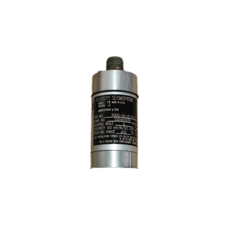
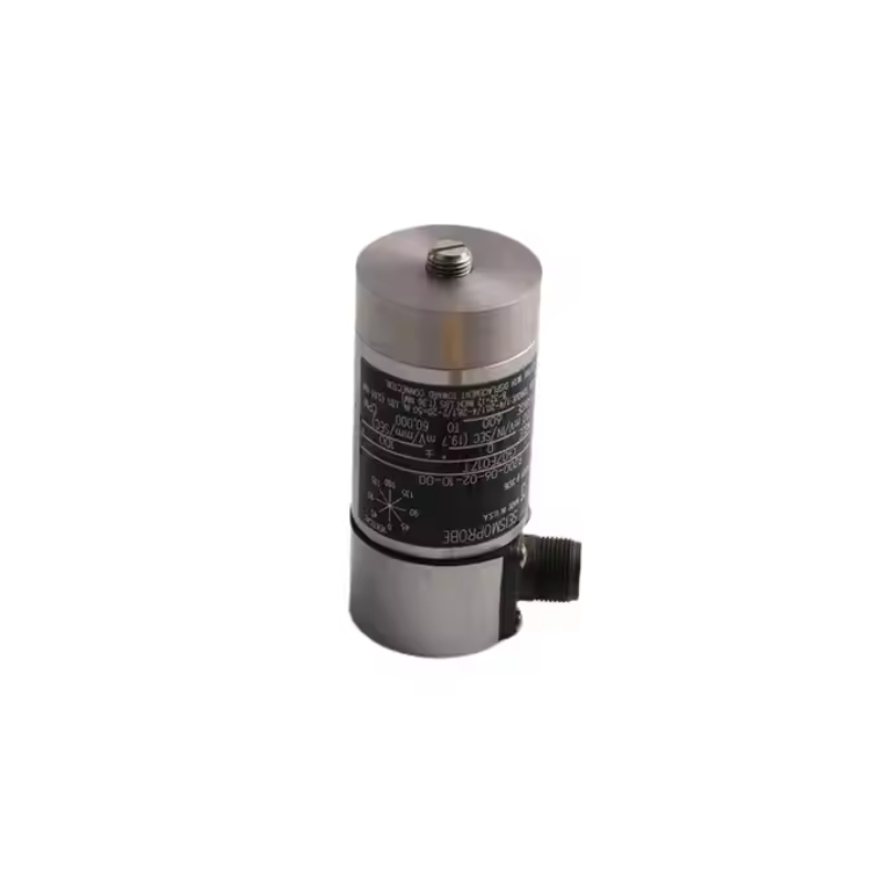
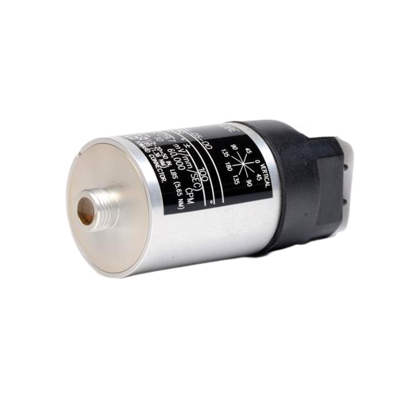
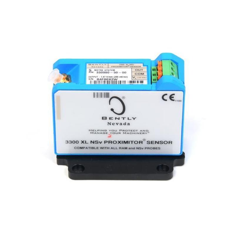
- Bently Nevada
- 9200-06-32-08-02
- Seismoprobe Velocity Transducers
- USA
- 102 mm x 44 mm x 40 mm
- 0.3kg
- Xiamen, China
- New & In Stock
- T/T, PayPal, Western Union
- 1 Year
- 1-3 Working Days
- DHL, UPS, TNT, FedEx and EMS.
- 24-Hour Service
- COO
- 4
Our advantage

Global Logistics
We have a 10-year logistics and express cooperation agreement, so our products can be shipped to any place in the world.

Brand new and original
Our products are imported in bulk from the place of origin. Because of the cooperative relationship, our products are all original and 100% new.

24-hour service
We provide 7*24 hours service to our customers. We will be there whenever you need us.

Price advantage
All our products are priced very favorably because we have our own warehouse and supply.
| Company Information | |||
| [email protected] | |||
| Mobile | +8615980777398 | ||
| +8615980777398 | |||
| 15980777398 |
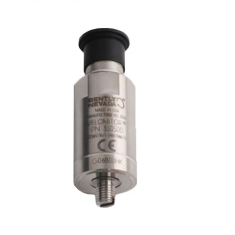
Bently Nevada 9200-06-32-08-02 — Product Specifications, Introduction, Applications, Advantages, and Related Models
1. Product Overview
The 9200-06-32-08-02 is a model number associated with industrial vibration-monitoring instrumentation. Before specifying its detailed technical characteristics, it is important to distinguish this model from similarly numbered sensor products: the 9200 family is associated with seismic vibration transducers, which are used to measure mechanical vibration in industrial equipment.
A seismic vibration transducer typically converts the vibration of a machine housing, bearing pedestal, or other mounting surface into an electrical signal. The signal can then be processed by compatible monitoring equipment to assess vibration levels and changes in machine behavior.
The complete suffix 9200-06-32-08-02 appears to identify a particular configuration. However, without the applicable ordering specification, the precise meanings of every suffix, along with the exact mounting thread, connector, output sensitivity, enclosure dimensions, and weight, cannot be established reliably from the part number alone.
The following technical overview therefore identifies the product family and its general operating principles while clearly marking model-specific values that require confirmation. This avoids treating estimated dimensions or typical family characteristics as guaranteed specifications for the exact unit.
2. Detailed Technical Parameters
The 9200 series is a two-wire velocity transducer family designed to measure absolute vibration of a machine casing, bearing housing, or supporting structure. The transducer uses a moving-coil principle to generate an electrical output proportional to vibration velocity.
The following table gives the main family specifications and the configuration details that can be identified from the model structure. The approval suffix 02 should be confirmed against the original ordering specification, as the exact meaning of this code is not established here.
| Parameter | Specification |
|---|---|
| Model | 9200-06-32-08-02 |
| Brand | Bently Nevada |
| Product series | 9200 Seismoprobe Velocity Transducers |
| Product type | Two-wire velocity transducer |
| Measurement principle | Moving-coil electromagnetic velocity sensing |
| Primary measurement | Absolute vibration velocity of the mounting surface |
| Mounting-angle / minimum-frequency option | 06 — 0° orientation; nominal minimum operating frequency 10 Hz |
| Cable / connector option | 32 — 32 ft (approximately 9.8 m) integral cable option |
| Mounting-base option | 08 — isolated rectangular flange |
| Approval option | 02 — exact approval meaning requires confirmation against the ordering specification |
| Typical sensitivity | 20 mV/mm/s (500 mV/in/s), subject to the specified configuration |
| Typical frequency response | Approximately 10 Hz to 1,000 Hz for the 06 mounting/frequency option; confirm the complete system specification |
| Electrical configuration | Two-wire output |
| External power requirement | The transducer is self-generating; any downstream monitoring or signal-conditioning requirements must still be checked |
| Typical case material | Anodized aluminum |
| Environmental protection | Industrial construction; the final protection level depends on the connector, integral cable, and installation |
| Typical operating temperature | Approximately -29°C to +121°C |
| Typical body height | Approximately 102 mm (4 in), depending on the connector and mounting configuration |
| Typical body diameter | Approximately 41 mm (1.6 in) |
| Cable length | Approximately 9.8 m |
| Overall installed dimensions | Depends on the mounting flange, connector, cable routing, and installation arrangement |
| Shipping/package dimensions | Not confirmed for this exact configuration |
| Weight (kg) | Approximately 0.30 kg is a typical reference for the basic transducer body; the exact weight of the 9.8 m cable assembly is unconfirmed |
| Mounting arrangement | Isolated rectangular flange configuration |
| Typical use | Vibration monitoring of bearing housings, machine casings, and structural supports |
| Typical equipment | Pumps, motors, fans, compressors, and other rotating machinery |
| System interface | Compatible vibration-monitoring equipment that accepts the transducer’s velocity signal |
2.1 Model Number Breakdown
| Code segment | Interpretation | Configuration |
|---|---|---|
| 9200 | Product family | Two-wire Seismoprobe velocity transducer |
| 06 | Mounting orientation / minimum operating frequency | 0° orientation, nominal 10 Hz minimum operating frequency |
| 32 | Cable option | 32 ft (approximately 9.8 m) integral cable |
| 08 | Mounting-base option | Isolated rectangular flange |
| 02 | Approval option | Confirm the precise approval designation before ordering |
The cable option is especially important. A 32 ft cable may be suitable when the transducer is located some distance from the monitoring cabinet, but the routing path, cable protection, grounding arrangement, and input requirements must all be considered.
The mounting-base option is equally important because the base determines how the transducer is secured to the machine. A rectangular flange and an isolated rectangular flange should not be assumed to have the same electrical or mechanical characteristics.
3. Product Introduction
3.1 General Description
The 9200 Seismoprobe velocity transducer is an industrial vibration sensor designed to measure the vibration velocity of a surface to which it is mounted. Typical measurement locations include bearing housings, machine casings, and structural supports.
The 9200-06-32-08-02 combines the 9200 transducer design with a specified mounting orientation and frequency option, a 32 ft integral cable, and an isolated rectangular mounting flange. The approval configuration must be confirmed before use in a regulated or hazardous environment.
Unlike a proximity probe, which measures relative displacement between a probe tip and a conductive target, a seismic velocity transducer measures vibration of the structure on which it is installed. This makes it suitable for applications where casing or bearing-housing vibration is the measurement of interest.
3.2 Working Principle
The transducer uses electromagnetic induction. A moving-coil assembly moves in response to vibration, producing an electrical signal related to the velocity of that movement.
As the machine casing or bearing housing vibrates, the transducer responds to the motion of its mounting point. The generated signal can then be received by compatible monitoring equipment for display, trending, alarm processing, or further analysis.
The transducer does not independently identify a particular mechanical fault. Instead, it provides vibration data that can be assessed alongside machine speed, load, operating conditions, historical trends, and other diagnostic information.
3.3 Two-Wire Design
The 9200 series uses a two-wire output arrangement. Because the sensing element generates its own signal, the transducer does not require the same type of external excitation used by many powered electronic sensors.
The connected monitoring equipment must still provide a suitable input for the transducer signal. Wiring polarity, cable shielding, grounding, and input impedance should be checked against the intended monitoring system.
3.4 Integral Cable Configuration
The “32” cable option represents an integral cable length of approximately 32 ft (9.8 m). This arrangement can simplify the physical connection between the transducer and the monitoring-system interface.
An integral cable can reduce the number of field connection points, but it also makes cable routing and handling important. The cable should be protected from crushing, abrasion, excessive bending, hot surfaces, and mechanical interference.
The installed cable length should be sufficient for the complete route without unnecessary tension. Extra cable should be secured appropriately rather than left hanging where it could be damaged.
3.5 Isolated Rectangular Flange
The “08” mounting-base option identifies an isolated rectangular flange configuration. The flange provides a defined mounting interface, while the isolation arrangement helps manage the electrical relationship between the transducer body and the mounting structure.
The exact isolation characteristics and mounting hardware should be confirmed against the intended installation. The mounting surface must be sufficiently rigid, and the flange should be installed in accordance with the equipment’s mounting requirements.
3.6 Role in a Machinery-Monitoring System
The transducer normally operates as one part of a wider monitoring arrangement. A typical system includes the vibration transducer, field wiring, a compatible monitoring input, and equipment used to display or process the vibration signal.
Depending on the system configuration, the measured velocity signal can support overall vibration monitoring, trending, alarm generation, and maintenance assessment.
The quality of the measurement depends on mounting rigidity, orientation, cable condition, signal compatibility, and the operating characteristics of the machine.
4. Product Applications
4.1 Industrial Pumps
Pumps may develop increased casing vibration because of hydraulic disturbances, imbalance, misalignment, looseness, bearing problems, or other operating conditions.
A velocity transducer mounted on a suitable pump bearing housing or casing can provide vibration data for monitoring trends. Maintenance personnel can compare the signal against established baselines and alarm limits to determine whether further inspection is required.
The 9200 transducer is most suitable where casing or structural vibration is the required measurement, rather than direct measurement of shaft displacement.
4.2 Electric Motors
Large electric motors can experience vibration associated with rotor imbalance, misalignment, loose mounting, bearing deterioration, or electrical and mechanical operating conditions.
A casing-mounted velocity transducer can help monitor the overall vibration response of the motor structure. Measurements can be recorded over time and reviewed during routine maintenance.
For meaningful results, the mounting position should be selected according to the motor design and monitoring plan. A single measurement location may not capture every vibration direction or every possible fault.
4.3 Fans and Blowers
Fans and blowers are commonly monitored because imbalance, structural looseness, blade damage, and bearing issues can lead to changes in vibration.
A seismic velocity transducer installed on a rigid bearing housing or support can measure vibration of the structure. Its output may be used to establish operating baselines and identify changes that warrant further investigation.
The sensor’s orientation and mounting arrangement should be appropriate for the expected vibration direction.
4.4 Compressors
Industrial compressors often operate continuously and may be included in plant condition-monitoring programs.
A casing-mounted velocity transducer can provide useful information about the vibration of compressor housings and supports. This can complement other monitoring methods, including shaft-displacement measurements where the compressor design requires them.
The transducer should be selected according to the required frequency response, mounting location, cable route, and monitoring-system input.
4.5 Gearboxes and Mechanical Drives
Gearboxes and mechanical drives may exhibit vibration related to gear-mesh forces, imbalance, misalignment, bearing behavior, or structural looseness.
A velocity transducer can monitor the vibration response of the gearbox housing or support structure. The resulting data may be trended to identify changes in machine behavior.
The sensor does not directly measure gear-tooth damage or lubrication condition. Such diagnoses require suitable signal analysis and, where necessary, complementary measurements.
4.6 General Industrial Machinery
The 9200 series may also be used on other machines where casing vibration is the required measurement. Examples include selected mixers, process machines, auxiliary equipment, and industrial drives.
The suitability of the sensor depends on the machine’s vibration characteristics, the required measurement range, the operating environment, and the monitoring input.
4.7 Continuous Condition Monitoring
Where the transducer is connected to a compatible monitoring system, its signal can be used for continuous or periodic vibration monitoring.
Long-term trending can help maintenance teams identify gradual changes in vibration level. Alarm thresholds should be established according to the equipment’s operating requirements and the site’s maintenance procedures rather than applying one universal limit to all machines.
5. Product Advantages
5.1 Direct Measurement of Structural Vibration
The transducer is intended to measure vibration velocity at the mounting point. This is useful when the engineering requirement focuses on bearing-housing, casing, or support vibration.
It provides a different measurement perspective from a proximity probe, which measures relative movement between the probe and a conductive target.
5.2 Self-Generating Sensing Principle
The moving-coil design generates an electrical signal in response to vibration. This reduces the need for a separate excitation supply at the sensing element.
The connected monitoring equipment must nevertheless be compatible with the output signal and the electrical characteristics of the transducer.
5.3 Long Integral Cable
The 32 ft cable option allows the transducer to be installed at a distance from the monitoring interface, subject to the permitted cable arrangement and signal requirements.
An integral cable can reduce the number of field connection points. Proper cable support and routing remain necessary to protect the installation.
5.4 Defined Mounting Interface
The isolated rectangular flange provides a specified mounting arrangement for equipment designed to accept it.
A suitable flange installation can support repeatable mounting and make replacement planning more straightforward. The mounting surface must be rigid, clean, and mechanically compatible with the transducer.
5.5 Industrial Construction
The 9200 family is designed for industrial vibration-monitoring applications. Its metal housing provides mechanical support for the sensing assembly.
The actual durability of the completed installation depends on the precise configuration, mounting quality, cable protection, environmental exposure, and maintenance practices.
5.6 Useful for Vibration Trending
When connected to suitable monitoring equipment, the transducer can supply a signal that is trended over time.
Changes in the vibration signal can help identify when an operating condition deserves investigation. Reliable interpretation depends on establishing a baseline and considering the machine’s operating speed, load, and other relevant conditions.
5.7 Practical for Retrofit Projects
The 9200 series may be appropriate for maintenance or retrofit projects where an existing monitoring system is designed for this type of velocity transducer.
Before replacement, the technician should confirm the mounting flange, orientation, minimum operating frequency, cable length, approval requirements, and monitoring-system compatibility.
6. Brand and Product Series
| Item | Description |
|---|---|
| Brand | Bently Nevada |
| Product series | 9200 Seismoprobe Velocity Transducers |
| Product category | Industrial vibration sensor |
| Model | 9200-06-32-08-02 |
| Measurement principle | Moving-coil electromagnetic sensing |
| Output | Two-wire velocity signal |
| Mounting configuration | Isolated rectangular flange |
| Cable configuration | 32 ft (approximately 9.8 m) integral cable |
| Typical measurement location | Bearing housing, machine casing, or structural support |
| Typical applications | Pumps, motors, fans, blowers, compressors, and selected gearboxes |
| Main function | Measurement of absolute vibration velocity at the mounting point |
| Related equipment | Compatible vibration-monitoring inputs and data acquisition systems |
The 9200 series is intended for vibration measurement at the machine structure. It should not be confused with proximity probes or electronic monitoring modules, which perform different functions within a machinery-monitoring system.
7. Five Related Models in the Same Series
The following are comparison candidates from the 9200 series. The cable-option codes shown represent different nominal integral cable lengths, while the other configuration fields are retained as comparison examples.
The exact validity of the approval suffix and the complete configuration should be confirmed before ordering. The dimensions and weights below distinguish typical transducer-body specifications from the cable assembly and shipping package.
| Model | Product type | Main parameters | Dimensions | Weight (kg) |
|---|---|---|---|---|
| 9200-06-10-08-00 | Two-wire velocity transducer | 0° mounting orientation; nominal 10 Hz minimum frequency; 10 ft (3.0 m) cable option; isolated rectangular flange; no approvals specified by suffix 00 | Typical body height 102 mm; diameter 41 mm; cable approximately 3.0 m | Typical bare transducer approximately 0.30 kg; complete assembly weight unconfirmed |
| 9200-06-15-08-00 | Two-wire velocity transducer | 0° mounting orientation; nominal 10 Hz minimum frequency; 15 ft (4.6 m) cable option; isolated rectangular flange | Typical body height 102 mm; diameter 41 mm; cable approximately 4.6 m | Typical bare transducer approximately 0.30 kg; complete assembly weight unconfirmed |
| 9200-06-22-08-00 | Two-wire velocity transducer | 0° mounting orientation; nominal 10 Hz minimum frequency; 22 ft (6.7 m) cable option; isolated rectangular flange | Typical body height 102 mm; diameter 41 mm; cable approximately 6.7 m | Typical bare transducer approximately 0.30 kg; complete assembly weight unconfirmed |
| 9200-06-32-08-00 | Two-wire velocity transducer | 0° mounting orientation; nominal 10 Hz minimum frequency; 32 ft (9.8 m) cable option; isolated rectangular flange | Typical body height 102 mm; diameter 41 mm; cable approximately 9.8 m | Typical bare transducer approximately 0.30 kg; complete assembly weight unconfirmed |
| 9200-06-50-08-00 | Two-wire velocity transducer | 0° mounting orientation; nominal 10 Hz minimum frequency; 50 ft (15.2 m) cable option; isolated rectangular flange | Typical body height 102 mm; diameter 41 mm; cable approximately 15.2 m | Typical bare transducer approximately 0.30 kg; complete assembly weight unconfirmed |
Important: The models above are configuration examples, not confirmed direct replacements for 9200-06-32-08-02. Approval requirements, mounting compatibility, cable length, and monitoring-system input must be checked before choosing an alternative.
8. Five Other Related or Common Models
The following products represent other commonly encountered options in the broader vibration-monitoring range. They have different functions and should not be regarded as direct replacements for the 9200 transducer.
| Model | Product category | Main parameters and function | Dimensions | Weight (kg) |
|---|---|---|---|---|
| 9200-06-02-01-00 | Two-wire velocity transducer | 0° orientation; nominal 10 Hz minimum frequency; side-mounted connector without integral cable; circular base with 1/4-20 UNC stud; no additional approval specified | Typical height approximately 102 mm; diameter approximately 41 mm; overall dimensions depend on connector and base | Typical transducer-body weight approximately 0.30 kg |
| 9200-06-02-10-00 | Two-wire velocity transducer | 0° orientation; nominal 10 Hz minimum frequency; side-mounted connector without integral cable; circular base with M10 × 1 stud; no additional approval specified | Typical height approximately 102 mm; diameter approximately 41 mm | Typical transducer-body weight approximately 0.30 kg |
| 74712-01 | Seismoprobe velocity transducer | Related velocity-transducer family; configuration and connector details should be confirmed against the complete part number | Typical height approximately 102 mm; diameter approximately 41 mm, depending on configuration | Typical body weight approximately 0.48 kg |
| 3300/55 | Vibration monitoring instrument family | Vibration monitoring equipment; exact function and hardware configuration depend on the particular model and installed system | Exact dimensions depend on the specific instrument version | Exact model-specific weight unconfirmed |
| 3500/42M | Proximitor/seismic monitoring module | Monitoring module for compatible proximity and seismic transducer channels in a configured machinery-monitoring rack | Rack-module dimensions depend on the specific hardware and rack arrangement | Exact module-specific weight unconfirmed |
The 9200 and 74712 models are the closest functional comparisons in this table because they belong to the seismic velocity-transducer category. The other products are included as broader system-related options, not as equivalent sensor replacements.
9. Installation and Maintenance Considerations
9.1 Mounting Surface
The transducer should be mounted on a suitable, rigid surface. Loose mounting hardware, uneven contact, or a flexible support can alter the measured vibration and make the readings less representative of the machine’s actual behavior.
The isolated rectangular flange must match the intended mounting interface. Check the dimensions and mounting-hole arrangement before installation.
9.2 Mounting Orientation
The “06” option is associated with a 0° mounting orientation and a nominal minimum operating frequency of 10 Hz.
The sensor should be installed according to the intended orientation and the applicable specification. Incorrect orientation or mounting can affect the response to the vibration being measured.
9.3 Cable Routing
The 32 ft cable should be routed away from moving components, sharp edges, and excessive heat. It should be secured so that its own movement does not place unnecessary mechanical stress on the transducer or connection.
The cable should not be sharply bent, crushed, or pulled tight. Where the cable passes through a panel or enclosure, appropriate protection should be provided.
9.4 Electrical Connection
Verify the signal input requirements before connecting the transducer to monitoring equipment. Check polarity, shielding, grounding, and input compatibility against the installation design.
A compatible two-wire input is necessary to obtain meaningful measurements. The wiring should also be inspected for damage and poor connections during maintenance.
9.5 Verification of the Measurement
After installation, confirm that the signal is stable and that its behavior is consistent with the machine’s operating condition.
Where possible, compare the new readings with an established baseline. Any significant change should be evaluated in context rather than attributed to a specific fault solely from the sensor signal.
9.6 Approval and Environmental Requirements
The exact meaning of the “02” approval suffix should be confirmed before use in hazardous or regulated environments.
The actual unit’s marking, installation method, cable arrangement, and connected equipment must meet the requirements of the application. Do not assume that a similar model’s approval automatically applies to this configuration.
10. Procurement Checklist
| Check item | Requirement | Reason |
|---|---|---|
| Complete part number | 9200-06-32-08-02 | Identifies the intended configuration |
| Measurement type | Velocity transducer | Confirms that casing vibration is the required measurement |
| Mounting orientation | Option 06 | Ensures the intended orientation and frequency option |
| Cable length | 32 ft (approximately 9.8 m) | Confirms the required cable reach |
| Mounting base | Option 08, isolated rectangular flange | Ensures mechanical fit and correct mounting arrangement |
| Approval configuration | Confirm option 02 against the ordering specification | Prevents an incorrect approval assumption |
| Dimensions | Verify the full assembly drawing | Ensures clearance and mounting compatibility |
| Weight (kg) | Confirm actual assembly and shipping weight | Supports handling and logistics |
| Signal input | Compatible two-wire velocity input | Ensures electrical compatibility |
| Operating environment | Verify temperature, vibration, and environmental limits | Ensures suitability for the installation |
| Replacement compatibility | Compare the full configuration with the existing unit | Reduces the risk of incorrect substitution |
11. Final Summary
The Bently Nevada 9200-06-32-08-02 is associated with the 9200 Seismoprobe velocity-transducer family, which is used to measure vibration velocity at a machine casing, bearing housing, or other suitable mounting surface.
Its identifiable configuration features include the 0° mounting/frequency option, a 32 ft (approximately 9.8 m) integral cable, and an isolated rectangular flange. Typical 9200-family body dimensions are approximately 102 mm high and 41 mm in diameter, with a typical bare transducer weight of around 0.30 kg. These figures should not be treated as the exact dimensions or weight of the complete cable-equipped assembly.
The sensor is suitable for applications requiring structural vibration measurements on pumps, motors, fans, compressors, and other machinery when the connected monitoring equipment accepts its signal. Correct mounting, cable routing, electrical compatibility, and approval verification are essential to a reliable installation.
Before ordering or replacing this model, confirm the full part number, mounting configuration, cable length, approval suffix, complete assembly dimensions, and actual weight.