

ProductPRODUCT
Featured products
Contact Us
- Schneider
- VW3M3403
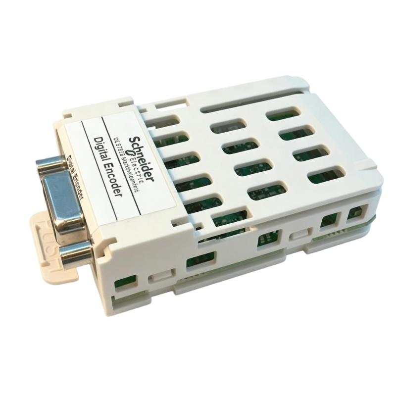
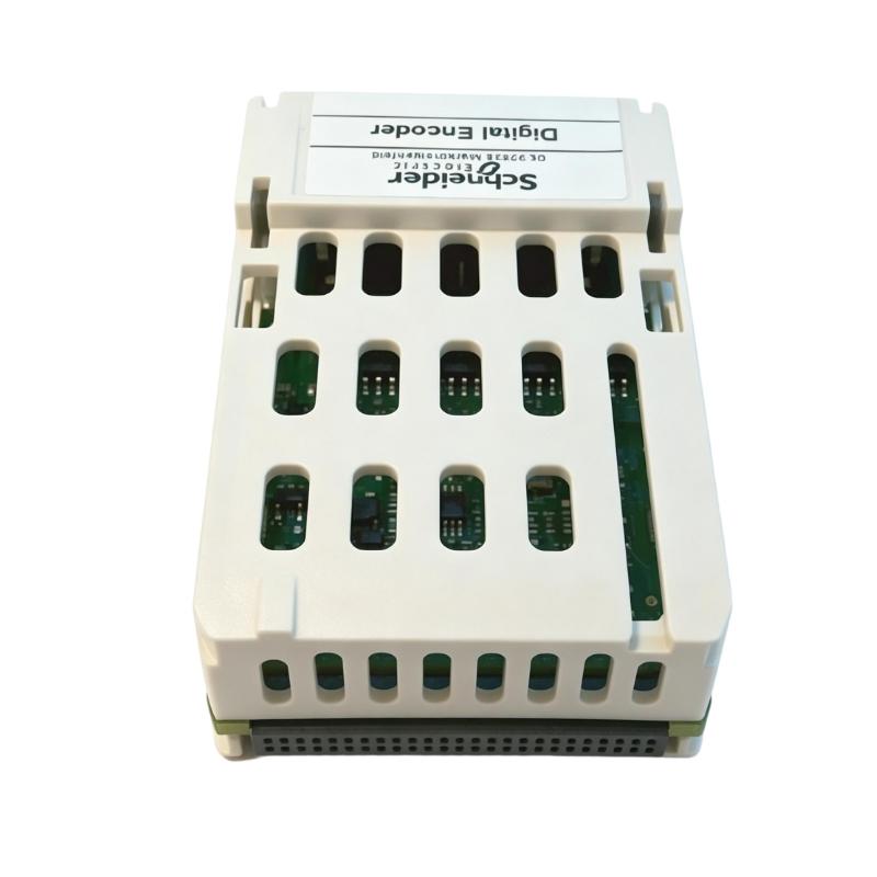
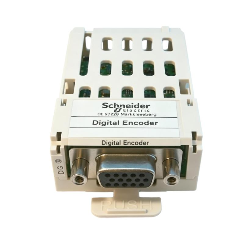
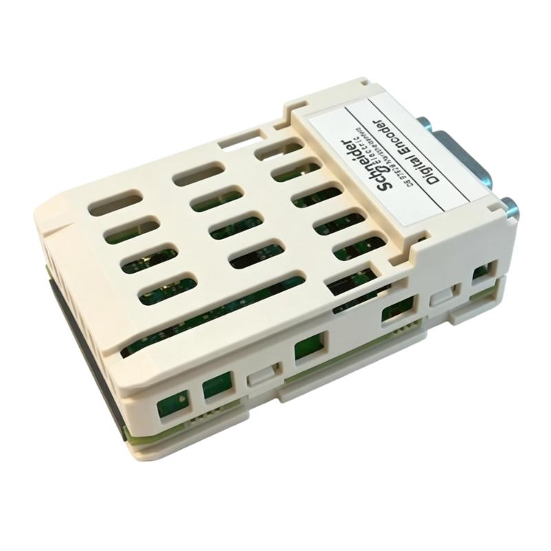
- Encoder Interface Module
- France
- 89 x 41 x 61 mm
- 0.057 kg
- Xiamen, China
- New & In Stock
- T/T, PayPal, Western Union
- 1 Year
- 1-3 Working Days
- DHL, UPS, TNT, FedEx and EMS.
- 24-Hour Service
- COO
- 4
Our advantage

Global Logistics
We have a 10-year logistics and express cooperation agreement, so our products can be shipped to any place in the world.

Brand new and original
Our products are imported in bulk from the place of origin. Because of the cooperative relationship, our products are all original and 100% new.

24-hour service
We provide 7*24 hours service to our customers. We will be there whenever you need us.

Price advantage
All our products are priced very favorably because we have our own warehouse and supply.
| Company Information | |||
| [email protected] | |||
| Mobile | +8615980777398 | ||
| +8615980777398 | |||
| 15980777398 |
1. Product Overview
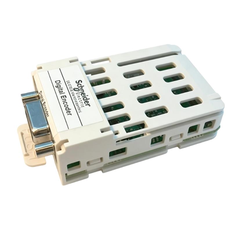
The Schneider VW3M3403 Encoder Interface Module is an industrial automation component identified for encoder interface applications. Encoder interfaces are important in motion control systems because they support the connection and integration of feedback devices used to monitor position, speed, or movement, depending on the specific hardware architecture.
In industrial environments, encoder feedback can help controllers and drive systems coordinate motor operation, improve motion monitoring, and maintain consistent machine performance. Selecting the correct interface component is therefore essential for ensuring that the encoder, drive, controller, and associated equipment operate as intended.
The Schneider VW3M3403 has supplied dimensions of 89 × 41 × 61 mm and a listed weight of 0.057 kg. Its compact size may be useful when planning equipment layouts and managing available space in electrical cabinets or machine control assemblies.
Before installing or replacing this module, engineers should verify its precise function, supported encoder types, electrical characteristics, connection requirements, and compatibility with the installed Schneider Electric equipment. The model designation alone should not be used to determine signal types, pin assignments, or supported hardware combinations.
2. Technical Specifications
| Parameter | Specification |
|---|---|
| Brand | Schneider Electric |
| Model | VW3M3403 |
| Product Type | Encoder Interface Module |
| Product Category | Industrial Automation and Motion Control |
| Dimensions | 89 × 41 × 61 mm |
| Weight | 0.057 kg |
| Primary Function | Encoder interface application, subject to model-specific verification |
| Typical System Role | Integration of encoder feedback with compatible automation equipment |
| Encoder Compatibility | Verify the supported encoder types and electrical interface |
| Electrical Requirements | Confirm from the applicable technical documentation |
| Connection Method | Verify the approved connector and wiring arrangement |
| System Compatibility | Confirm compatibility with the installed drive, controller, and associated modules |
| Installation Requirements | Follow the approved mounting and installation instructions |
The dimensions and weight above are based on the supplied product information. Detailed electrical ratings, supported feedback signals, connector assignments, and system compatibility should be confirmed before installation or commissioning.
3. Function and Working Principle
An encoder interface module generally provides a connection between an encoder feedback device and compatible control or motion equipment. The exact function depends on the module’s design and the manufacturer’s specified application.
An encoder detects movement and converts it into electrical signals that can be interpreted by a compatible control system. Depending on the encoder type, these signals may represent incremental movement, absolute position, rotational speed, or another motion-related measurement.
A typical encoder feedback arrangement may include the following components:
- Encoder: Detects shaft rotation, linear movement, or another measurable position change.
- Encoder interface: Provides the designated electrical or signal interface between the feedback device and the receiving equipment.
- Drive or controller: Processes supported feedback information and uses it for monitoring or control.
- Motor or machine mechanism: Produces the movement being measured.
- Engineering and diagnostic tools: Help technicians verify configuration and investigate feedback-related faults.
The VW3M3403 should be integrated according to its documented role in the relevant Schneider Electric system. Its exact signal-processing capabilities and supported encoder formats must be verified rather than inferred from the general term “encoder interface.”
Encoder Feedback in Motion Control
In a suitable motion control system, feedback information can help the controller or drive compare expected movement with actual movement. This information may be used for position monitoring, speed regulation, synchronization, or fault detection, depending on the system design.
A correctly matched interface can help maintain reliable signal transmission between the encoder and the receiving equipment. An incompatible interface, incorrect wiring arrangement, or unsupported encoder type may prevent the system from recognizing feedback or may cause unstable operation.
Importance of Correct Interface Selection
Encoder devices differ in electrical characteristics, output formats, resolution, and connection requirements. Before selecting the VW3M3403 for an application, confirm that its documented specifications match the encoder and the target automation equipment.
4. Role in Industrial Automation Systems
Encoder feedback is widely used in industrial automation where machines require movement monitoring, coordinated operation, or repeatable positioning. Interface components can help connect feedback devices to the appropriate control hardware.
4.1 Motion Monitoring
Feedback signals can provide information about the movement of motors, shafts, conveyors, and other mechanisms. When supported by the installed system, this information helps operators and controllers monitor machine operation.
4.2 Position Control
Some automation systems use encoder feedback to measure movement toward a defined position. Accurate positioning depends on the encoder, interface, drive, controller, mechanical assembly, and configuration working together correctly.
4.3 Speed Regulation
Encoder feedback may be used by compatible drive systems to measure rotational speed or movement rate. The supported feedback method and control function depend on the equipment specifications.
4.4 Coordinated Machine Operation
Packaging machines, production lines, and material handling systems may require several mechanisms to operate in coordination. Suitable feedback interfaces can form part of the control architecture used to monitor movement and support synchronization.
4.5 Equipment Diagnostics
Feedback-related faults can affect positioning, speed measurement, or machine availability. Correct module identification and access to system diagnostics help maintenance personnel determine whether a problem originates in the encoder, interface, wiring, configuration, or associated equipment.
5. Industrial Applications
The VW3M3403 may be evaluated for an application when its verified specifications match the requirements of the target automation system. The following examples describe common environments where encoder interfaces are used; they do not independently confirm suitability for every listed application.
Manufacturing and Assembly Equipment
Automated manufacturing equipment often requires movement monitoring and repeatable machine sequences. Encoder feedback can help compatible control systems coordinate motors and mechanisms during production.
Packaging Machinery
Packaging lines may use feedback devices to monitor conveyor movement, product positioning, and the operation of rotating or indexing mechanisms. The appropriate interface must support the encoder and motion equipment selected for the machine.
Conveyor and Material Handling Systems
Conveyors and transfer mechanisms may use encoders to measure movement and coordinate equipment operation. Interface selection should account for the feedback device, drive architecture, environmental conditions, and required control performance.
Automated Positioning Systems
Some industrial machines use encoder feedback to monitor linear or rotary positioning. The complete system must support the required feedback format and positioning function before the VW3M3403 is selected.
Machine Upgrades and Maintenance
During equipment modernization, an encoder interface may need to be replaced because of a hardware fault, a maintenance requirement, or a system redesign. Engineers should confirm the exact part number and functional compatibility before introducing a replacement into the existing installation.
6. Installation and System Integration
Proper installation helps protect the module and reduces the risk of feedback errors. The following procedure is a general checklist and does not replace the model-specific instructions.
Step 1: Verify the Product Model
Confirm that the product label identifies the module as Schneider VW3M3403. Compare the model with the system drawings, bill of materials, and original component where applicable.
Do not substitute a similar-looking module based only on its dimensions or product description.
Step 2: Isolate the Equipment
Place the machine in a safe state and isolate the relevant power sources according to the site’s lockout/tagout procedure. Verify that the equipment is de-energized before handling electrical connections.
If the module is part of a drive or motion control assembly, follow the applicable procedures for stored energy and electrical safety.
Step 3: Inspect the Module and Installation Area
Check the housing, connectors, and mounting area for visible damage, contamination, corrosion, or signs of overheating. Confirm that the installation location meets the environmental and mechanical requirements specified for the product.
Step 4: Verify Encoder Compatibility
Before making connections, identify the encoder model and review its electrical output characteristics. Confirm that the VW3M3403 supports the intended encoder and that the receiving drive or controller supports the resulting interface.
Do not assume that all incremental, absolute, or other encoder types are interchangeable.
Step 5: Confirm Wiring and Connection Requirements
Use the approved wiring diagram to identify the required terminals, connectors, signal conductors, shielding, and grounding arrangements. Verify any specified cable type and maximum permitted cable length.
Do not infer connector pin assignments or signal voltages from the module name.
Step 6: Install the Module
Mount and connect the module according to the applicable installation instructions. Ensure that connectors are properly engaged and that cables are routed and secured without excessive strain.
Avoid excessive force when handling connectors or fitting the module into an assembly.
Step 7: Review System Configuration
Check whether the installed drive or controller requires specific hardware settings, parameter adjustments, or engineering software configuration for the encoder interface. Use only settings supported by the documented system configuration.
Step 8: Restore Power and Perform Checks
After completing the installation and inspection, restore power in accordance with the approved commissioning procedure. Review available status indicators and controller or drive diagnostics.
Confirm that the encoder feedback is recognized and that no unexpected faults are present.
Step 9: Validate Operation
Perform appropriate functional tests before returning the equipment to normal production. Where applicable, verify feedback consistency, movement direction, speed readings, and positioning behavior using the approved commissioning procedure.
Testing should be conducted by qualified personnel under conditions that protect people and equipment.
7. Common Problems and Troubleshooting
Encoder-related problems may originate from the feedback device, interface module, cabling, configuration, drive, controller, or mechanical system. A systematic approach helps isolate the cause without replacing components unnecessarily.
| Symptom | Possible Causes | Recommended Checks |
|---|---|---|
| Encoder feedback is not detected | Incorrect connection, incompatible encoder, missing configuration, or module fault | Verify the model, wiring diagram, supported encoder type, and system diagnostics |
| Position readings are inconsistent | Signal interference, wiring problems, incorrect configuration, or encoder malfunction | Inspect cables and connections; confirm configuration and feedback specifications |
| Speed feedback is unstable | Electrical noise, loose connections, encoder problems, or incompatible signal characteristics | Check cable routing, shielding, connections, and encoder compatibility |
| Feedback direction is incorrect | Encoder orientation, configuration, or wiring arrangement differs from the intended setup | Verify the approved connection diagram and configuration settings |
| Drive or controller reports a feedback fault | Unsupported interface, electrical issue, configuration mismatch, or hardware failure | Record the fault message and compare the installed system with its approved configuration |
| Intermittent feedback loss | Damaged cable, loose connector, electrical interference, or environmental conditions | Inspect connectors and cables and investigate the installation environment |
| Fault remains after module replacement | The original cause may be external to the interface module | Check the encoder, cable, power supply, controller, drive, and configuration |
7.1 Check the Encoder and Cable
Inspect the encoder and its cable for physical damage, loose connections, contamination, or signs of wear. Verify that the cable type and length meet the relevant system requirements.
Where electrical measurements are necessary, use suitable instruments and follow the approved safety procedure.
7.2 Verify Signal Compatibility
Different encoders can use different output formats and electrical signaling methods. Confirm that the encoder’s documented characteristics match the requirements of the VW3M3403 and the receiving equipment.
7.3 Review Configuration and Diagnostics
Record error messages and relevant status information before changing parameters. Review the drive or controller configuration to determine whether the installed feedback device and interface are correctly defined.
Avoid changing unrelated parameters during troubleshooting because doing so may introduce additional faults.
7.4 Investigate Electrical Interference
Encoder signals may be affected by electrical noise or unsuitable cable routing. Inspect the installation against the manufacturer’s recommendations for cable separation, shielding, grounding, and routing near motors or power conductors.
7.5 Determine Whether the Module Is Faulty
If the encoder, wiring, configuration, and associated equipment have been checked but the problem remains, further testing may be required. Replace the module only after confirming the fault and verifying that the replacement is suitable for the system.
Do not open or modify the module unless an authorized repair procedure specifically permits it.
8. Preventive Maintenance and Reliability
Preventive maintenance can help identify potential feedback problems before they cause an unexpected machine stoppage.
- Inspect connections: Check connectors and cable terminations for looseness, damage, or contamination.
- Examine encoder cables: Look for abrasion, crushing, excessive bending, or other signs of mechanical wear.
- Review diagnostic history: Record recurring feedback faults and investigate their underlying causes.
- Maintain cabinet conditions: Keep the installation within the specified temperature, humidity, and contamination limits.
- Check cable routing: Confirm that encoder cables remain routed according to the system’s noise-control and grounding requirements.
- Protect spare modules: Store replacement components in suitable conditions and protect connectors from electrostatic discharge and contamination.
- Keep configuration records: Maintain accurate hardware lists, wiring drawings, parameter records, and commissioning information.
- Document replacements: Record the installed part number and relevant configuration changes during maintenance.
Maintenance intervals should reflect the operating environment, machine criticality, manufacturer recommendations, and site maintenance policy.
9. Compatible System Components
Successful integration depends on the complete motion control architecture rather than the interface module alone. The following component categories should be reviewed when planning an installation or replacement.
| Component Category | Integration Considerations |
|---|---|
| Encoder or feedback device | Confirm supported encoder types, output characteristics, resolution, and connection requirements |
| Servo drive or compatible receiving equipment | Verify interface support and the intended feedback configuration |
| Motion controller or PLC | Confirm required hardware support, control functions, and configuration requirements |
| Encoder cable | Check connector type, cable specification, shielding, routing, and permitted length |
| Power supply | Verify the supply requirements of the connected equipment and feedback device |
| Mounting assembly | Confirm mechanical fit and the approved installation arrangement |
| Engineering software | Verify support for the installed hardware and required configuration functions |
| Diagnostic equipment | Ensure suitable tools are available for investigating feedback and connection faults |
These are component categories to consider during integration, not a confirmed list of compatible Schneider Electric part numbers. Exact compatibility must be established from the specifications for the installed system.
10. Replacement and Alternative Selection
When replacing the Schneider VW3M3403 Encoder Interface Module, technical equivalence should take priority over appearance, dimensions, or price.
| Selection Factor | What to Verify |
|---|---|
| Exact model | Confirm the complete part number: VW3M3403 |
| Functional role | Ensure the replacement performs the same documented interface function |
| Encoder support | Compare the supported encoder types and feedback characteristics |
| Electrical interface | Confirm signal requirements and electrical ratings |
| Connection arrangement | Verify connectors, pin assignments, and approved cable requirements |
| Mechanical dimensions | Compare the supplied dimensions of 89 × 41 × 61 mm |
| Weight | Compare the supplied weight of 0.057 kg where relevant to equipment planning |
| System compatibility | Confirm support from the receiving drive, controller, and associated equipment |
| Configuration requirements | Determine whether hardware settings or software parameters need to be updated |
| Product condition | Assess authenticity, storage condition, testing status, and warranty where applicable |
A module with a similar appearance or product description is not automatically a valid substitute. If the VW3M3403 is unavailable, any proposed alternative should be checked against the complete technical requirements and approved system configuration.
11. Key Benefits of Correct Encoder Interface Selection
Choosing a suitable encoder interface supports the reliable integration of feedback devices into industrial motion control systems.
Appropriate Feedback Integration
A correctly matched interface helps establish the intended connection between the encoder and the receiving automation equipment.
Support for Motion Monitoring
Where supported by the installed system, encoder feedback can provide information used to monitor position, movement, or speed.
Compact Equipment Planning
The supplied dimensions of 89 × 41 × 61 mm provide a reference for preliminary layout planning and replacement checks.
Lightweight Design
The listed weight of 0.057 kg can help with component inventory and equipment handling considerations. Mechanical mounting requirements must still be observed.
More Efficient Maintenance
Correct part identification, clear system documentation, and organized diagnostic records help technicians investigate feedback problems and select suitable replacement components.
These benefits depend on the verified technical function of the module, correct installation, and compatibility with the surrounding equipment.
12. Technical FAQs
Q1: What is the Schneider VW3M3403?
The Schneider VW3M3403 is identified in the supplied product information as an Encoder Interface Module. Its exact capabilities and supported system configuration should be confirmed from the product label and applicable technical documentation.
Q2: What are the dimensions of the VW3M3403?
The supplied dimensions are 89 × 41 × 61 mm.
Q3: How much does the VW3M3403 weigh?
The supplied product weight is 0.057 kg.
Q4: What does an encoder interface module do?
In general, an encoder interface provides a designated connection between a feedback device and compatible automation equipment. The precise function depends on the specific module and system architecture.
Q5: Can the VW3M3403 be used with any encoder?
No. Encoder compatibility depends on the module’s supported signal types, electrical characteristics, connection requirements, and the capabilities of the receiving equipment. These details must be verified before installation.
Q6: What should be checked before installing the module?
Confirm the complete model number, mounting requirements, encoder compatibility, electrical specifications, connector arrangement, wiring diagram, and compatibility with the drive or controller.
Q7: Why might an automation system fail to recognize encoder feedback?
Possible causes include incorrect wiring, an incompatible encoder, a damaged cable, configuration errors, electrical interference, or a hardware fault. Check the available diagnostic information before replacing components.
Q8: Can a similar encoder interface be used as a replacement?
Only if its documented function, electrical interface, supported feedback devices, connection arrangement, and system compatibility meet the requirements of the existing installation. Similar dimensions alone are not sufficient.
Q9: Does the VW3M3403 require software configuration?
Configuration requirements depend on the module’s role and the connected automation equipment. Check the applicable documentation to determine whether hardware settings, drive parameters, or engineering software configuration are required.
Q10: What should be done if feedback faults continue after replacement?
Inspect the encoder, cables, connections, configuration, and receiving equipment. Review fault messages and verify the replacement’s compatibility. If the problem persists, follow an approved diagnostic procedure to isolate the cause.
13. Conclusion
The Schneider VW3M3403 Encoder Interface Module is an industrial automation component identified for encoder interface applications. With supplied dimensions of 89 × 41 × 61 mm and a weight of 0.057 kg, it can be identified and evaluated during equipment planning, maintenance, and replacement activities.
Reliable integration requires more than matching the model number and physical dimensions. Engineers should verify the module’s exact function, supported encoder types, electrical characteristics, connection requirements, and compatibility with the receiving drive or controller before commissioning.
Careful installation, appropriate cable routing, configuration checks, systematic troubleshooting, and documented preventive maintenance can help reduce avoidable feedback faults and support dependable operation in compatible industrial automation systems.