

ProductPRODUCT
Featured products
Contact Us
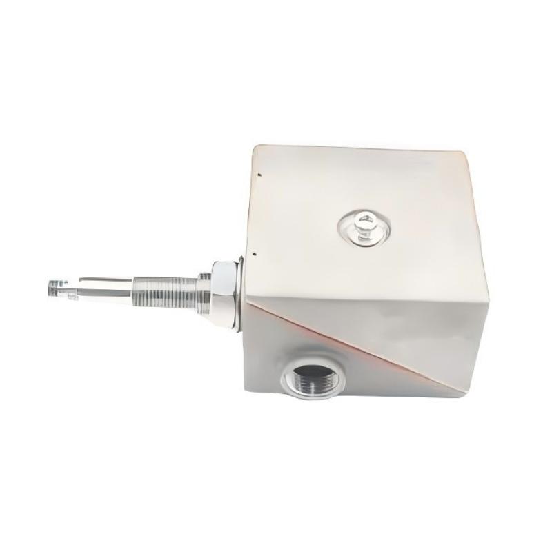
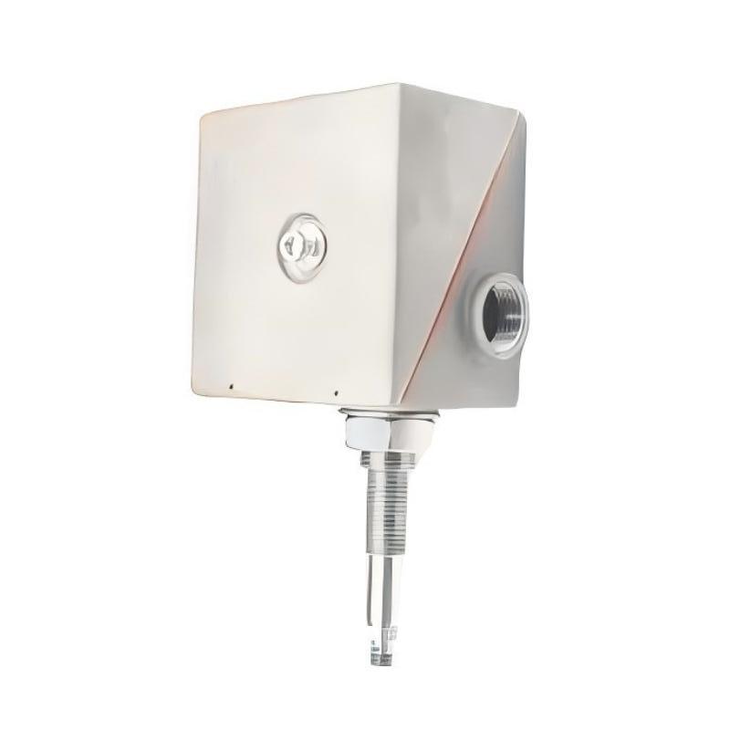
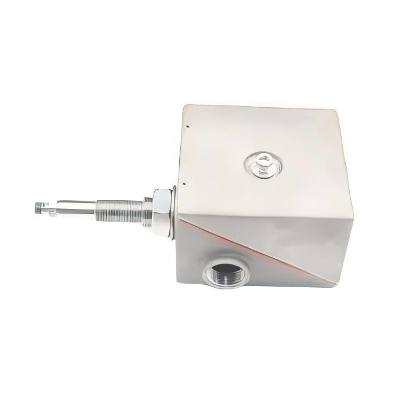
- Bently Nevada
- 26530-12-10-03-018-230-22-04-00
- Dual Probe Transducer System
- USA
- 1 meter
- 3 kg
- Xiamen, China
- New & In Stock
- T/T, PayPal, Western Union
- 1 Year
- 1-3 Working Days
- DHL, UPS, TNT, FedEx and EMS.
- 24-Hour Service
- COO
- 3
Our advantage

Global Logistics
We have a 10-year logistics and express cooperation agreement, so our products can be shipped to any place in the world.

Brand new and original
Our products are imported in bulk from the place of origin. Because of the cooperative relationship, our products are all original and 100% new.

24-hour service
We provide 7*24 hours service to our customers. We will be there whenever you need us.

Price advantage
All our products are priced very favorably because we have our own warehouse and supply.
| Company Information | |||
| [email protected] | |||
| Mobile | +8615980777398 | ||
| +8615980777398 | |||
| 15980777398 |
Product Overview
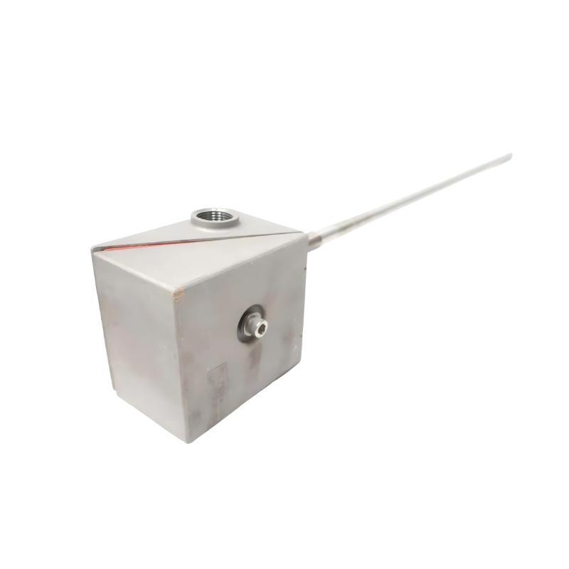
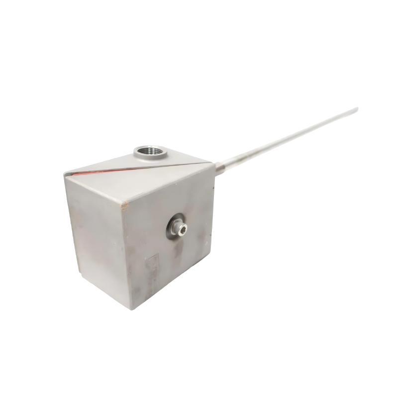
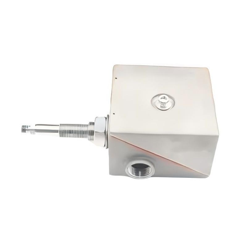
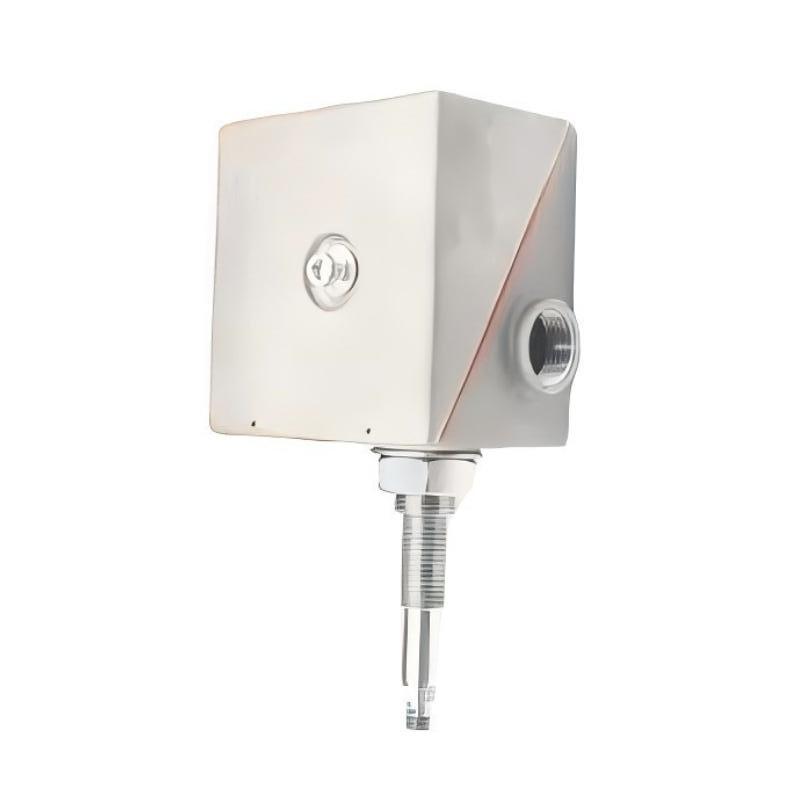
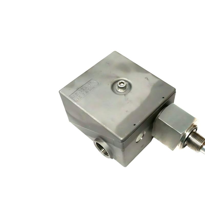
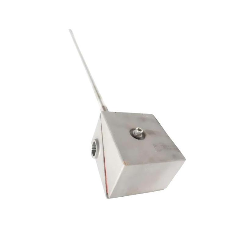
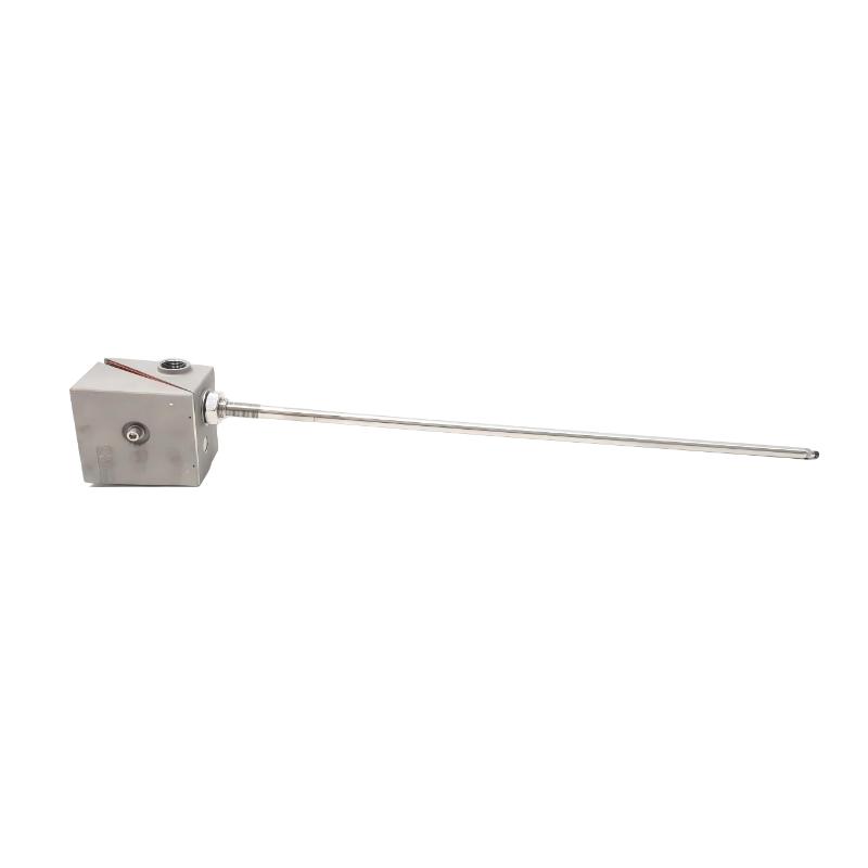
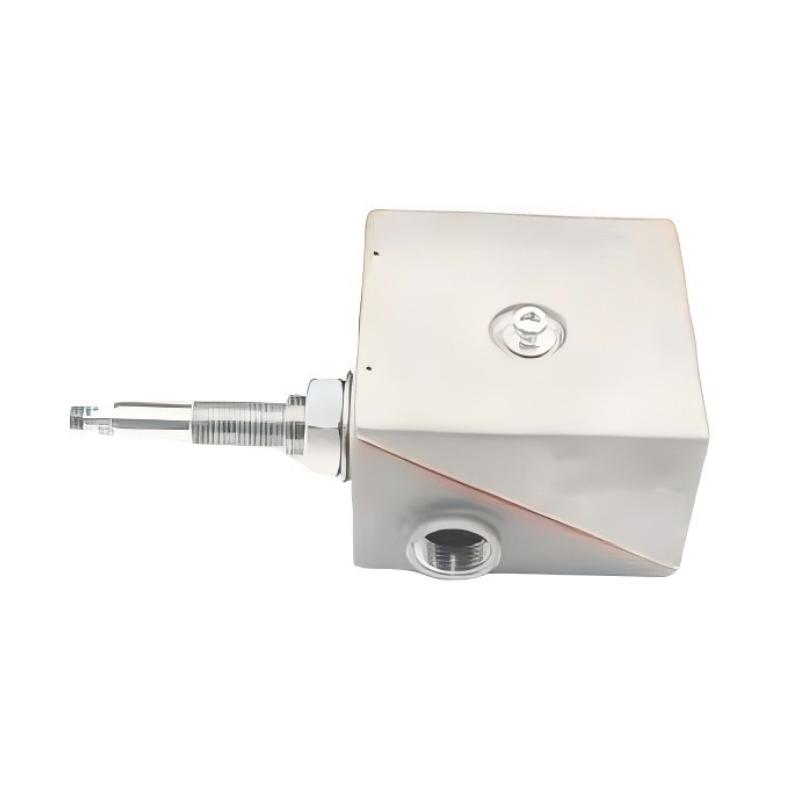
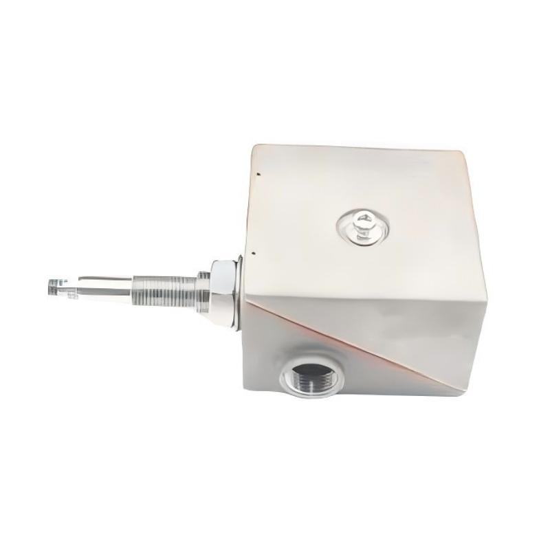
The Bently Nevada 26530-12-10-03-018-230-22-04-00 Dual Probe Transducer System combines a 3300 XL 8 mm proximity probe with a high-temperature, two-wire Seismoprobe. The assembly is used in rotating machinery monitoring installations where engineers need to assess shaft movement relative to its mounting point alongside vibration of the supporting machine structure.
The proximity probe measures the gap between its sensing tip and the conductive shaft surface. Changes in this gap indicate shaft position and dynamic movement relative to the probe mounting location. The Seismoprobe measures vibration of the bearing housing or casing, supplying a separate measurement of structural movement.
These two measurements provide different information about machine behavior. A rotor can move relative to its bearing while the bearing housing also vibrates under mechanical forces. The proximity channel captures the relative shaft movement, whereas the seismic channel records vibration of the supporting structure. Evaluating both signals helps engineers distinguish rotor-related motion from casing vibration.
The 26530-12-10-03-018-230-22-04-00 uses a 1-meter probe lead, a 3/4-14 NPT adapter connection, an 018 adapter-length option, and a 230 probe-penetration option. The configuration also specifies a high-temperature, two-wire Seismoprobe, one 3/4-14 NPT plug fitting, and no optional probe support/oil seal.
The extended penetration arrangement is intended for installations where the shaft target is located deeper within the machine casing or bearing structure. The probe must reach the intended sensing surface while maintaining the appropriate measurement gap. Mounting rigidity and clearance around the probe are also important, particularly when the installation is exposed to vibration during startup or changing operating loads.
The dual-transducer system supports four related measurements: shaft relative radial position, shaft relative radial dynamic motion, machine-casing absolute vibration, and shaft absolute motion calculated from the relevant signals. The final measurement requires compatible monitoring equipment to process the seismic signal and relative shaft displacement appropriately.
In compressor and turbine applications, comparing the two signals can help maintenance personnel investigate changes in vibration during startup, speed transitions, and load changes. A rise in shaft-relative vibration accompanied by increased casing vibration presents a different diagnostic pattern from a change in the proximity signal alone.
The assembly is one part of a complete machinery monitoring installation. Correct mechanical mounting, suitable signal conditioning, proper electrical connections, and compatible monitoring channels are necessary for meaningful measurements. Alarm and protection functions depend on the wider monitoring system rather than the transducer assembly alone.
Technical Specifications
| Parameter | Specification |
|---|---|
| Manufacturer | Bently Nevada |
| Model | 26530-12-10-03-018-230-22-04-00 |
| Product Type | Dual Probe Transducer System |
| Product Series | 26530 |
| Proximity Probe | 3300 XL 8 mm |
| Probe Lead Length | 1 meter |
| Adapter Thread | 3/4-14 NPT |
| Adapter Length Option | 018 |
| Nominal Adapter Length | 1.8 inches |
| Probe Penetration Option | 230 |
| Nominal Probe Penetration | 23.0 inches |
| Velocity Transducer | High-temperature, two-wire Seismoprobe |
| Velocity Transducer Orientation | 0° ± 100° |
| Fittings Option | 04 — One 3/4-14 NPT plug |
| Probe Support/Oil Seal Option | 00 — Not required |
| Measurement Technology | Eddy-current proximity sensing and seismic velocity sensing |
| Shaft Measurement | Relative radial position and relative radial dynamic motion |
| Casing Measurement | Absolute vibration |
| Combined Measurement | Shaft absolute motion through appropriate signal processing |
| Proximity Probe Temperature Range | -51°C to +177°C |
| High-Temperature Seismoprobe Temperature Range | -29°C to +204°C |
| Minimum Operating Frequency for Velocity Transducer | 600 cpm |
| Shipping Weight | 3 kg |
Product Features
- Dual-transducer arrangement: Combines shaft-displacement sensing and structural vibration measurement in one assembly.
- 3300 XL 8 mm proximity probe: Detects changes in the distance between the sensing tip and conductive shaft surface.
- High-temperature Seismoprobe: Measures supporting-structure vibration using the specified two-wire configuration.
- Extended probe penetration: Accommodates installations requiring a longer reach to the shaft measurement target.
- NPT mounting connection: Uses a 3/4-14 NPT adapter interface.
- Specified probe lead: Incorporates the 1-meter proximity probe lead configuration.
- Independent measurement signals: Allows shaft-relative motion and casing vibration to be evaluated separately.
- Combined motion assessment: Supports shaft absolute-motion calculations through compatible monitoring equipment.
- Machinery monitoring integration: Supplies complementary signals for rotating equipment condition monitoring.
Working Principle
The 26530 Dual Probe Transducer System uses two sensing methods to measure different aspects of rotating machinery movement.
The 3300 XL 8 mm proximity probe operates through eddy-current sensing. Its electromagnetic field interacts with the conductive shaft surface, and the electrical response changes as the gap between the probe tip and shaft changes. Compatible signal-conditioning equipment converts this response into a displacement measurement relative to the probe mounting point.
The high-temperature, two-wire Seismoprobe measures vibration of the supporting structure. Unlike the proximity probe, which detects the shaft-to-probe gap, the Seismoprobe responds to vibration of the bearing housing or casing. This second signal becomes particularly useful when the structure supporting the proximity probe is itself moving.
Shaft Surface → 3300 XL 8 mm Probe → Relative Displacement Signal
Bearing Housing → High-Temperature Seismoprobe → Structural Vibration Signal
Compatible Monitoring Equipment → Signal Processing → Shaft Absolute-Motion Assessment
The proximity channel records changes in relative shaft position and dynamic movement. The seismic channel supplies structural vibration data. When the monitoring system integrates the velocity signal into displacement and combines it appropriately with the relative shaft-displacement measurement, it can calculate shaft absolute motion.
Consider a compressor experiencing a change in vibration during a load transition. The rotor may move relative to its bearing while the housing responds to changing mechanical forces. The proximity probe records relative shaft movement, while the Seismoprobe measures the housing vibration. Examining both signals helps engineers understand how the rotor and supporting structure are responding.
The extended penetration configuration affects the mechanical installation. The probe must reach the intended conductive target without interference from surrounding components. Its gap must be adjusted correctly, and the mounting arrangement must remain mechanically stable to avoid introducing unwanted movement into the readings.
The Seismoprobe’s orientation and operating-frequency characteristics must also suit the application. This configuration specifies an orientation range of 0° ± 100° and a minimum operating frequency of 600 cpm. These characteristics should be considered when selecting the measurement location and interpreting data across the machine’s operating range.
The transducer assembly does not independently identify a mechanical fault or initiate a shutdown. Fault diagnosis, alarm decisions, and protective actions depend on the connected monitoring equipment, configured measurement channels, alarm limits, and machinery protection logic.
Role in a Rotating Machinery Monitoring System
The Bently Nevada 26530-12-10-03-018-230-22-04-00 supplies complementary sensor signals to a machinery monitoring system. Its proximity channel follows shaft movement relative to the mounting point, while its velocity channel measures vibration of the supporting structure.
Shaft Movement → Proximity Measurement
Casing Vibration → Seismic Measurement
Monitoring Channels → Signal Processing → Operator Display and Alarm Logic
| System Component | Function |
|---|---|
| Bently Nevada 26530 Dual Probe Transducer System | Combines proximity and velocity sensing in one housing |
| 3300 XL 8 mm Proximity Probe | Measures displacement between the probe tip and shaft surface |
| High-Temperature Two-Wire Seismoprobe | Measures vibration of the supporting structure |
| Probe Lead | Connects the proximity probe to its associated signal-conditioning circuit |
| NPT Adapter | Establishes the mechanical mounting interface |
| Proximity Signal Conditioner | Converts the probe response into a usable displacement signal |
| Velocity Monitoring Input | Receives the Seismoprobe signal |
| Machinery Monitoring Channels | Process individual measurements and configured alarm functions |
| Operator Interface | Displays measurement values, trends, and calculated measurements where supported |
For radial-bearing diagnostics, two suitable assemblies can be positioned along perpendicular X-Y axes. With compatible monitoring equipment, this arrangement supports shaft orbit analysis and shaft centerline evaluation using measurements from both radial directions.
Industrial Applications
| Application | Typical Use |
|---|---|
| Steam Turbines | Evaluating shaft-relative movement and casing vibration during startup and operation |
| Industrial Compressors | Comparing rotor movement with vibration of the supporting bearing housing |
| Centrifugal Compressor Trains | Monitoring shaft behavior under changing speed and process loads |
| Power Generation Equipment | Supporting vibration assessment of large rotating machinery |
| Refinery Machinery | Collecting complementary shaft and structural vibration measurements |
| Radial Bearing Monitoring | Measuring shaft displacement relative to the bearing support |
| Turbomachinery Diagnostics | Distinguishing shaft-relative movement from casing vibration |
| Shaft Orbit Analysis | Supplying measurements for X-Y analysis with suitable assemblies and monitoring equipment |
| Shaft Centerline Monitoring | Supporting position assessment through compatible monitoring equipment |
| Machinery Commissioning | Establishing baseline measurements for subsequent operating comparisons |
Installation and Maintenance
- Confirm the measurement location: Select a mounting point that provides access to the intended shaft target and a suitable mechanical reference on the bearing housing or casing.
- Check the adapter interface: Confirm that the machine mounting provision matches the specified 3/4-14 NPT adapter connection.
- Review the mounting geometry: Account for the 1.8-inch adapter-length option and 23.0-inch nominal probe penetration when assessing the installation drawing and available clearance.
- Inspect the target surface: Ensure the shaft surface is suitable for eddy-current measurement and that the probe faces the intended measurement area.
- Set the probe gap: Establish the initial clearance according to the applicable 3300 XL 8 mm installation procedure and the requirements of the connected signal-conditioning equipment.
- Secure the assembly: Tighten the mounting hardware according to the applicable installation requirements to prevent unwanted movement of the sensor housing during operation.
- Inspect the probe lead: Check the 1-meter lead for cuts, crushing, abrasion, and excessive strain before connecting the electrical circuit.
- Connect the velocity transducer: Follow the wiring requirements for the high-temperature, two-wire Seismoprobe and its compatible receiving input.
- Check sensor orientation: Position the velocity transducer within its specified orientation range and ensure that its measurement axis matches the intended monitoring function.
- Verify signal conditioning: Confirm that the proximity and velocity signals are connected to suitable inputs with the correct scaling and measurement configuration.
- Assess mechanical support: Check the extended probe mounting arrangement for adequate rigidity and potential resonance that could affect the measurement signals.
- Establish baseline readings: Record shaft-relative displacement and casing vibration under known operating conditions, then compare subsequent readings against these baseline measurements.
During maintenance, inspect the probe gap, mounting security, lead condition, and electrical connections. If the proximity and velocity signals show different trends, investigate the two measurement paths separately before attributing the change to rotor behavior or structural vibration.
Related Components
| Component | Function |
|---|---|
| Bently Nevada 26530 Dual Probe Transducer System | Combines shaft-relative displacement sensing with casing-vibration measurement |
| 3300 XL 8 mm Proximity Probe | Detects changes in the gap between the probe tip and conductive shaft surface |
| High-Temperature Two-Wire Seismoprobe | Measures vibration of the supporting machine structure |
| Compatible Proximity Signal Conditioner | Processes the proximity probe output |
| Compatible Velocity Monitoring Input | Receives the Seismoprobe signal |
| NPT Adapter and Mounting Hardware | Secures the assembly at the designated machine location |
| Probe Sleeve Support | Provides additional support where required by the installation |
| Machinery Monitoring Rack | Collects and processes the measurement signals |
| X-Y Measurement Arrangement | Supports radial orbit analysis when configured with two suitable assemblies |
Recommended Related Models
| Model | Product Type | Typical Application |
|---|---|---|
| Bently Nevada 26530-12-10-03-018-230-22-04-00 | Dual Probe Transducer System | Combined shaft-relative displacement and casing-vibration measurement |
| Bently Nevada 26530-12-10-03-018-225-22-04-00 | Dual Probe Transducer System | Related configuration with a different probe-penetration option |
| Bently Nevada 26530-12-10-03-018-210-22-04-00 | Dual Probe Transducer System | Alternative probe-penetration configuration |
| Bently Nevada 3300 XL 8 mm Proximity Probe | Proximity Probe | Shaft displacement measurement in a compatible transducer system |
| Bently Nevada 330500 Velomitor Sensor | Seismic Velocity Transducer | Structural vibration measurement in compatible monitoring applications |
Key Advantages
- Combines shaft-relative displacement and casing-vibration measurements in one assembly.
- Helps distinguish rotor movement from motion of the supporting structure.
- Uses a 3300 XL 8 mm proximity probe and a high-temperature, two-wire Seismoprobe.
- Supports shaft absolute-motion assessment through compatible signal processing.
- Accommodates an extended probe-penetration arrangement.
- Supplies complementary measurement data for rotating machinery diagnostics.
Technical FAQs
How does the dual-transducer system distinguish shaft-relative motion from structural vibration?
The proximity probe measures shaft movement relative to its mounting point, while the Seismoprobe measures vibration of the supporting structure. Comparing the signals helps compatible monitoring equipment distinguish relative shaft motion from casing vibration and calculate shaft absolute motion where supported.
What does the 230 probe-penetration option mean for installation planning?
The option specifies a nominal probe penetration of 23.0 inches. The installation must accommodate the required reach, target clearance, and mounting geometry while maintaining the appropriate sensing gap. The combined adapter and penetration arrangement must also remain within the applicable configuration limits.
Why is the high-temperature, two-wire Seismoprobe used in this assembly?
It provides a structural vibration measurement that complements the proximity probe’s shaft-displacement signal. Its specified temperature range and mounting orientation must suit the installation, and the two-wire output must connect to compatible receiving instrumentation.
What equipment is needed to calculate shaft absolute motion from this assembly?
Compatible monitoring equipment must process the proximity probe’s relative displacement signal and the Seismoprobe’s velocity signal. The seismic signal is integrated into displacement and combined appropriately with the relative shaft measurement to derive shaft absolute motion.