

ProductPRODUCT
Featured products
Contact Us
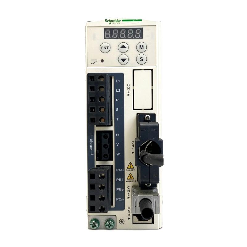
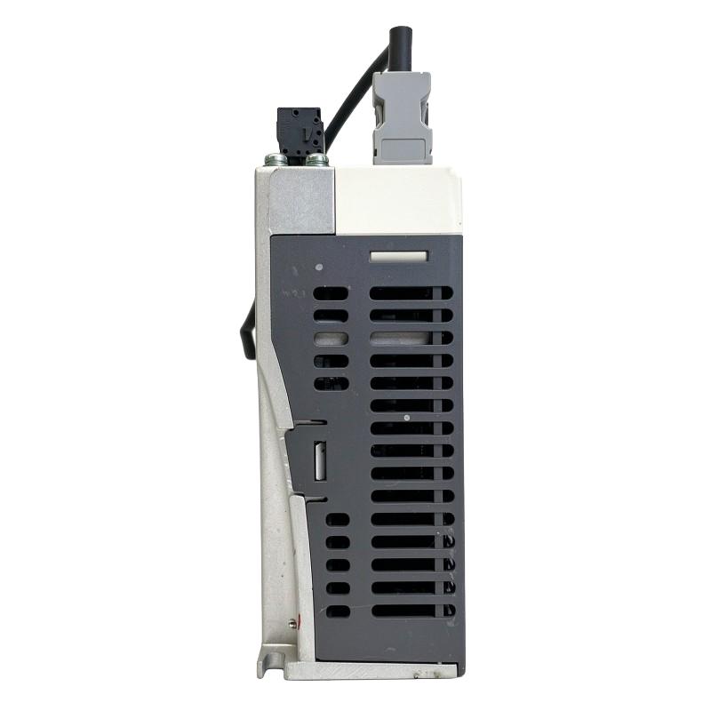
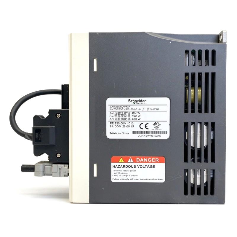
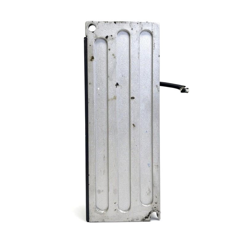
- Schneider
- LXM23DU04M3X
- Motion Servo Drive
- France
- 60 × 162 × 146 mm
- 1.7 kg
- Xiamen, China
- New & In Stock
- T/T, PayPal, Western Union
- 1 Year
- 1-3 Working Days
- DHL, UPS, TNT, FedEx and EMS.
- 24-Hour Service
- COO
- 4
Our advantage

Global Logistics
We have a 10-year logistics and express cooperation agreement, so our products can be shipped to any place in the world.

Brand new and original
Our products are imported in bulk from the place of origin. Because of the cooperative relationship, our products are all original and 100% new.

24-hour service
We provide 7*24 hours service to our customers. We will be there whenever you need us.

Price advantage
All our products are priced very favorably because we have our own warehouse and supply.
| Company Information | |||
| [email protected] | |||
| Mobile | +8615980777398 | ||
| +8615980777398 | |||
| 15980777398 |
Product Overview
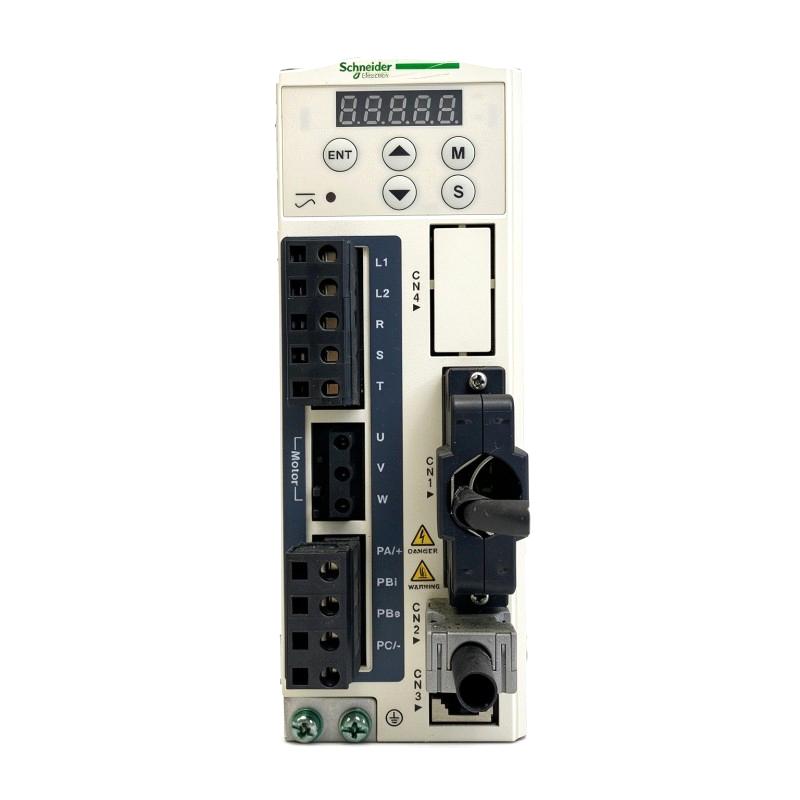
The Schneider Electric LXM23DU04M3X is a 400 W motion servo drive in the Lexium 23 Plus family. It controls compatible servo motors in machinery that requires repeatable positioning, adjustable speed, or controlled torque. The drive combines motor power regulation with encoder feedback, allowing it to respond to movement commands while monitoring the motor’s actual response.
This model suits compact automation axes where a conventional motor starter or basic speed controller cannot deliver the required positioning behavior. Typical applications include indexing mechanisms, component feeders, small assembly stations, and packaging equipment. In these machines, the servo axis may need to move a component to a defined position, pause for a processing operation, and return to motion as part of the next cycle.
The LXM23DU04M3X has a nominal output rating of 0.4 kW and supports single-phase 200–255 V AC or three-phase 170–255 V AC supply arrangements. Its control architecture includes programmable digital I/O, analog voltage inputs, and an integrated Modbus interface using RS-485. Position commands can also be supplied through the supported pulse-control interface, making the drive suitable for controllers that generate pulse-based movement instructions.
For example, a small automated assembly machine may use a servo motor to move a fixture beneath a press or inspection head. The controller issues the required movement command, while the drive regulates motor operation according to the selected control mode and configured motion parameters. Encoder feedback helps the drive track motor movement, and digital signals can coordinate the axis with the wider machine sequence.
The distinction between the LXM23D and LXM23A variants matters when integrating the drive into an existing control system. The LXM23DU04M3X uses the I/O-oriented configuration with integrated Modbus communication. It should not be treated as a CANopen-equipped LXM23A drive. The controller interface, signal wiring, and required communication method must match the selected variant.
The 400 W rating makes this model relevant to mechanisms that need more motor output than the smaller 200 W class while retaining a compact servo-control arrangement. Actual suitability depends on motor current, load inertia, acceleration requirements, transmission characteristics, and the frequency of movement cycles. A mechanism with frequent starts and stops may have different demands from one operating at a relatively constant speed.
In a working installation, the drive, motor, feedback cable, command source, and mechanical transmission function as a coordinated system. Correct configuration of these elements is necessary to achieve consistent movement and avoid unnecessary alarms during production.
Technical Specifications
| Parameter | Specification |
|---|---|
| Manufacturer | Schneider Electric |
| Model | LXM23DU04M3X |
| Product Type | Motion Servo Drive |
| Product Family | Lexium 23 Plus |
| Device Short Name | LXM23 |
| Nominal Power | 0.4 kW |
| Continuous Output Power | 400 W at 220 V |
| Continuous Output Current | 2.6 A |
| Rated Supply Voltage | 220 V AC |
| Single-Phase Supply Range | 200–255 V AC |
| Three-Phase Supply Range | 170–255 V AC |
| Supply Frequency | 50/60 Hz |
| Network Frequency Limits | 47.5–63 Hz |
| Command Interface | Pulse control and programmable I/O |
| Communication Interface | Integrated Modbus over RS-485 |
| Modbus Connector | RJ45, CN3 |
| Programmable Digital Inputs | 8 |
| Digital Input Voltage | 12–24 V DC |
| Digital Outputs | 5 |
| Digital Output Voltage | 12–24 V DC |
| Analog Inputs | 2 voltage inputs |
| Analog Input Range | -10 to +10 V |
| Feedback | Servo motor encoder |
| Control Functions | Position, speed, and torque control |
| Cooling Method | Natural convection |
| EMC Filter | Not integrated |
| Protection Rating | IP20; IP41 on the upper part with the protective cover fitted |
| Operating Temperature | 0–55°C |
| Relative Humidity | 5–85%, non-condensing |
| Mounting Position | Vertical, within the specified installation tolerance |
| Dimensions | 60 × 162 × 146 mm |
| Weight | 1.7 kg |
Product Features
- 400 W servo output: Suitable for compact motion axes requiring a moderate increase in motor power compared with lower-rated servo drives.
- Pulse-based positioning: Accepts supported pulse commands from a compatible motion controller.
- Three control functions: Supports position, speed, and torque control through the applicable configuration.
- Programmable digital inputs: Provides eight inputs for configured control signals and operating functions.
- Digital outputs: Offers five outputs for supported status and control signals.
- Analog voltage inputs: Includes two voltage inputs with a -10 to +10 V range for applicable command functions.
- Integrated Modbus: Supports serial data exchange through an RS-485 interface.
- Encoder feedback: Uses motor feedback to regulate movement and monitor the response to motion commands.
- Passive cooling: Uses natural convection, making cabinet ventilation and mounting clearance important installation considerations.
- Multiple supply arrangements: Supports the specified single-phase and three-phase AC supply ranges.
Working Principle
The LXM23DU04M3X receives motion commands through its supported control interface and regulates the electrical power delivered to the servo motor. The encoder supplies feedback about motor movement, allowing the drive to regulate the response according to the selected operating mode and configured parameters.
Motion Controller → Pulse or Analog Command → LXM23DU04M3X → Servo Motor → Mechanical Load
The feedback path connects the motor encoder to the drive. This allows the control system to monitor actual motor movement rather than relying solely on the command signal.
In position-control applications, a controller can send pulse commands representing the requested movement. The drive processes these commands and regulates the motor according to the configured pulse scaling, electronic gearing, acceleration, and deceleration settings. For an indexing mechanism, this arrangement allows the machine to move a fixture or component through repeatable increments.
The drive also supports configured internal motion sequences. Where this function is used, movement parameters and operating conditions are established in advance. Programmable digital inputs can then initiate supported actions or coordinate the sequence with other machine operations. This can reduce the amount of continuous command traffic required for machines that repeat a limited set of movements.
Speed control is useful when the motor must maintain a commanded speed rather than repeatedly move between fixed positions. Depending on the selected configuration, the reference can come from an analog voltage input or configured operating parameters. A feeder or roller mechanism, for example, may use speed control to maintain a consistent feed rate during a production cycle.
Torque control is used when regulating motor torque is the primary objective. The command source, torque limits, and operating conditions must be configured for the application. Mechanical safeguards remain necessary because torque control does not eliminate the risk of damage from a jammed mechanism or an unexpected load.
The integrated Modbus interface provides a separate communication path for supported data exchange with compatible control equipment. Communication uses an RS-485 physical interface, with transmission settings configured for the connected network. Modbus communication should not be confused with CANopen; the LXM23DU04M3X is the I/O-oriented variant.
During deceleration, a servo motor can return energy to the drive. Where frequent stopping or high load inertia produces substantial regenerative energy, an external braking resistor may be required. The braking arrangement must be selected according to the drive specifications and the machine’s operating cycle.
The final motion response depends on the complete system, including motor compatibility, encoder feedback, mechanical inertia, transmission backlash, and control parameters. Correct commissioning is essential to achieve the intended movement without excessive vibration, following errors, or repeated fault conditions.
Role in a Lexium 23 Motion Control System
The LXM23DU04M3X occupies the servo power and control stage between the machine controller and the driven mechanism. It processes the selected motion command, regulates motor output, and uses encoder feedback to control the motor’s response.
PLC or Motion Controller → Servo Drive → Servo Motor → Machine Axis
| System Component | Function |
|---|---|
| Schneider Electric LXM23DU04M3X | Regulates servo motor power and executes configured motion control |
| Compatible Servo Motor | Converts electrical power into mechanical movement |
| Motor Encoder | Supplies feedback for motor-motion regulation |
| PLC or Motion Controller | Generates positioning commands and coordinates machine sequences |
| Pulse Command Wiring | Transfers supported positioning signals to the drive |
| Digital I/O | Carries configured control and status signals |
| Analog Command Source | Supplies voltage references for supported control functions |
| Modbus RS-485 Network | Exchanges supported data with compatible control equipment |
| Servo Motor Power Cable | Carries drive output power to the motor |
| External Braking Resistor | Dissipates regenerative energy when required |
| Mechanical Transmission | Transfers motor movement to the driven mechanism |
Industrial Applications
| Application | Typical Use |
|---|---|
| Automated Assembly | Positioning parts for insertion, fastening, or pressing operations |
| Packaging Machinery | Controlling feed movements and indexing cycles |
| Component Feeding | Advancing workpieces by a defined distance |
| Inspection Equipment | Moving products into repeatable inspection positions |
| Labeling Machines | Regulating compatible feed and applicator mechanisms |
| Small Material Handling Systems | Operating servo-driven transfer mechanisms |
| Printing and Marking Equipment | Controlling feed movement and positioning |
| Automated Fixtures | Moving workholding devices between defined stations |
| Laboratory Automation | Controlling compatible low-power positioning mechanisms |
| Special-Purpose Machinery | Implementing programmed movement sequences for dedicated equipment |
The LXM23DU04M3X is most appropriate when the required motor output, command interface, feedback arrangement, and duty cycle match the needs of the machine.
Installation and Maintenance
- Confirm the supply configuration: Check that the available single-phase or three-phase AC supply falls within the drive’s specified voltage range.
- Match the motor ratings: Verify the servo motor’s rated current, power, voltage, encoder type, and feedback connection against the drive’s supported specifications.
- Prepare the control cabinet: Provide a suitable enclosure and sufficient ventilation for natural-convection cooling.
- Observe mounting requirements: Install the drive vertically within the specified tolerance and maintain the required clearances around the unit.
- Check grounding and circuit protection: Confirm protective grounding, supply-side protection, and correct electrical isolation before commissioning.
- Inspect power connections: Check the incoming supply and motor terminals for correct wiring, secure connections, and suitable cable ratings.
- Verify encoder feedback: Confirm that the encoder cable and connector match the motor and drive configuration. Route feedback wiring to limit electrical interference.
- Configure the command interface: Set up the pulse input or other applicable command source and confirm signal polarity, timing, and scaling.
- Assign digital I/O functions: Configure the required inputs and outputs, including applicable enable, reset, limit, and status functions.
- Set motion parameters: Adjust acceleration, deceleration, speed limits, positioning parameters, and other relevant settings to match the machine’s mechanics.
- Test the axis at reduced speed: Check motor direction, feedback response, stopping behavior, and command accuracy before running the production cycle.
- Record maintenance findings: Document parameter settings, alarms, wiring changes, motor details, and troubleshooting results for future maintenance.
If the motor does not reach its commanded position, inspect the command signals, encoder feedback, mechanical coupling, and active fault information before changing control parameters. This helps distinguish electrical configuration problems from mechanical resistance or unsuitable motion settings.
Related Components
| Component | Function |
|---|---|
| Schneider Electric LXM23DU04M3X | Controls a compatible servo motor using configured motion commands |
| Compatible Lexium Servo Motor | Produces the mechanical movement required by the application |
| Motor Encoder | Provides position and speed feedback |
| PLC or Motion Controller | Generates commands and coordinates machine operations |
| Pulse Command Cable | Transfers supported positioning signals from the controller |
| Servo Motor Power Cable | Connects the drive output to the motor |
| Encoder Feedback Cable | Transfers feedback signals to the drive |
| Modbus RS-485 Cable | Supports serial communication with compatible equipment |
| External Braking Resistor | Dissipates regenerative energy when required |
| Circuit Protection Devices | Provide supply-side electrical protection |
Recommended Related Models
| Model | Product Type | Typical Application |
|---|---|---|
| Schneider LXM23DU01M3X | Lexium 23 Plus Motion Servo Drive, 100 W | Compact axes with lower power requirements |
| Schneider LXM23DU02M3X | Lexium 23 Plus Motion Servo Drive, 200 W | Small positioning and feeding mechanisms |
| Schneider LXM23DU04M3X | Lexium 23 Plus Motion Servo Drive, 400 W | Servo axes requiring a 400 W nominal output |
| Schneider LXM23DU07M3X | Lexium 23 Plus Motion Servo Drive, 750 W | Applications requiring greater motor power |
| Schneider LXM23DU10M3X | Lexium 23 Plus Motion Servo Drive, 1 kW | Higher-load motion-control applications |
| Schneider LXM23DU15M3X | Lexium 23 Plus Motion Servo Drive, 1.5 kW | Servo mechanisms with higher power demands |
Key Advantages
- Supports 400 W servo motion applications.
- Provides pulse-based positioning control.
- Supports position, speed, and torque control functions.
- Includes programmable digital inputs and outputs.
- Offers analog voltage inputs for supported command arrangements.
- Integrates Modbus communication over RS-485.
- Uses encoder feedback for closed-loop motor regulation.
- Supports single-phase and three-phase supply arrangements within the specified limits.
Technical FAQs
How does pulse scaling affect positioning with the LXM23DU04M3X?
Pulse scaling determines how incoming command pulses correspond to motor movement. Incorrect electronic gearing or pulse settings can cause the axis to travel farther or shorter than expected. The configured scaling must match the controller’s output and the machine’s required movement.
Can the LXM23DU04M3X communicate directly with a Modbus controller?
The drive includes an integrated Modbus interface using two-wire RS-485. A compatible controller can exchange supported data when the communication settings, wiring, and drive configuration are correct.
What should be considered when connecting a servo motor to this 400 W drive?
Check the motor’s rated current, voltage, encoder compatibility, feedback connection, and supported drive-motor combination. The application’s load inertia and acceleration requirements must also fall within the drive’s capabilities.
Why might a servo axis produce an overvoltage fault during repeated stopping?
Repeated deceleration can return energy from the motor to the drive’s DC bus. If the regenerative energy exceeds what the system can handle, an overvoltage fault may occur. Review the deceleration profile, load inertia, stopping frequency, and braking arrangement against the drive’s specifications.