

ProductPRODUCT
Featured products
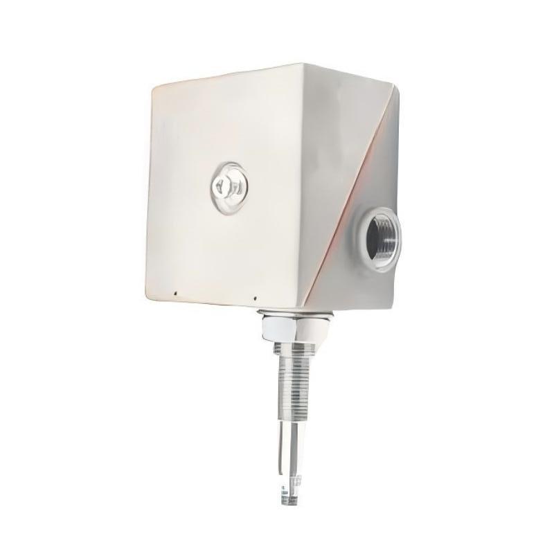
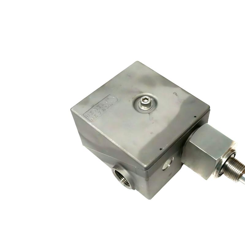
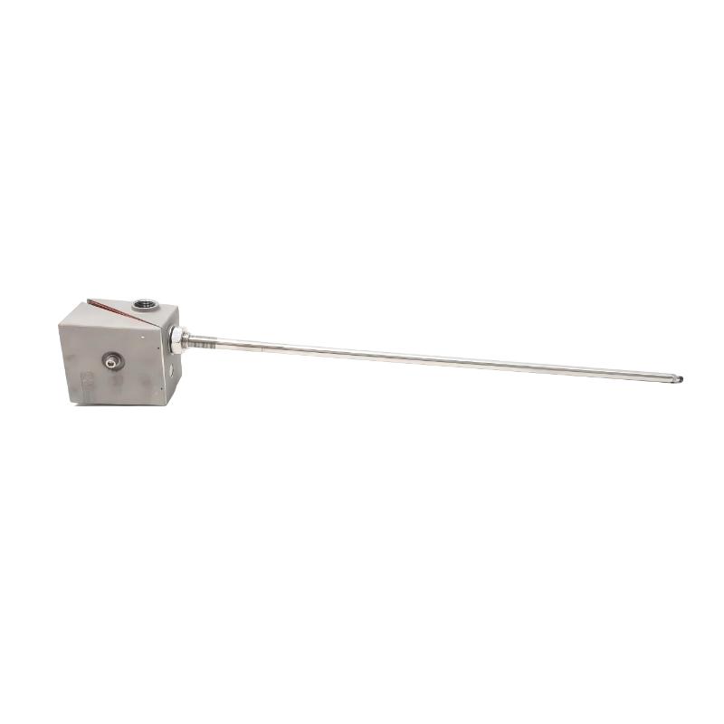
Contact Us
- Schneider
- VW3M1C12
- Connector
- France
- 86 x 74 x 52 mm
- 0.05 kg
- Xiamen, China
- New & In Stock
- T/T, PayPal, Western Union
- 1 Year
- 1-3 Working Days
- DHL, UPS, TNT, FedEx and EMS.
- 24-Hour Service
- COO
- 4
Our advantage

Global Logistics
We have a 10-year logistics and express cooperation agreement, so our products can be shipped to any place in the world.

Brand new and original
Our products are imported in bulk from the place of origin. Because of the cooperative relationship, our products are all original and 100% new.

24-hour service
We provide 7*24 hours service to our customers. We will be there whenever you need us.

Price advantage
All our products are priced very favorably because we have our own warehouse and supply.
| Company Information | |||
| [email protected] | |||
| Mobile | +8615980777398 | ||
| +8615980777398 | |||
| 15980777398 |
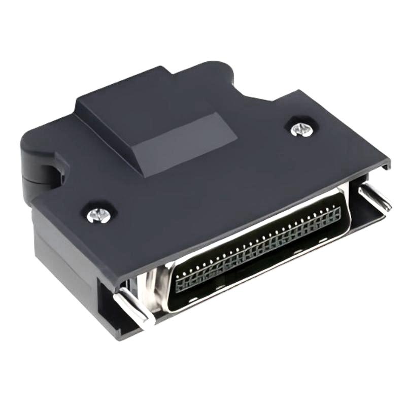
1. Product Overview
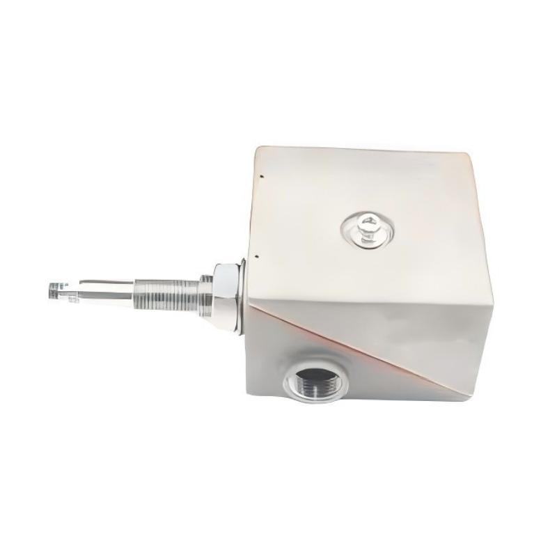
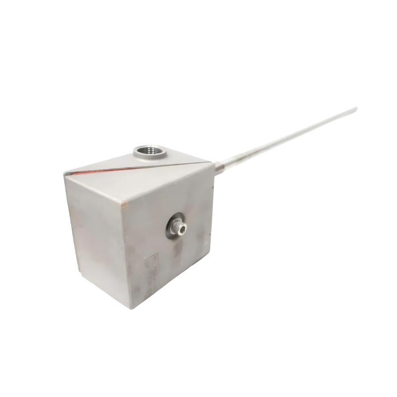
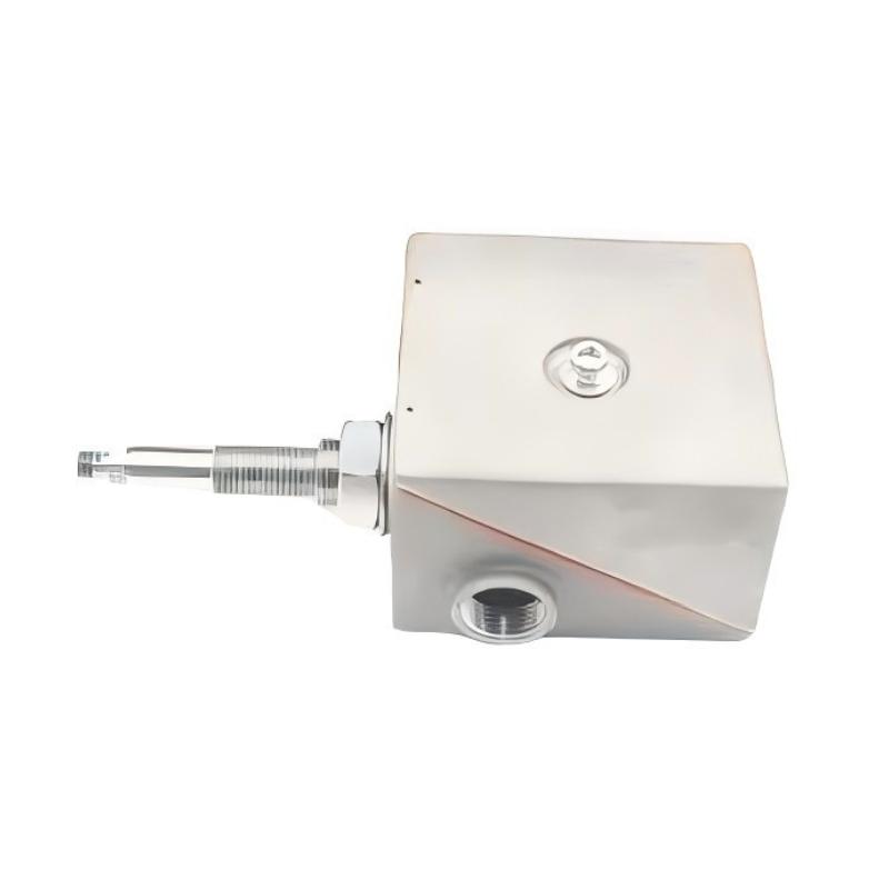
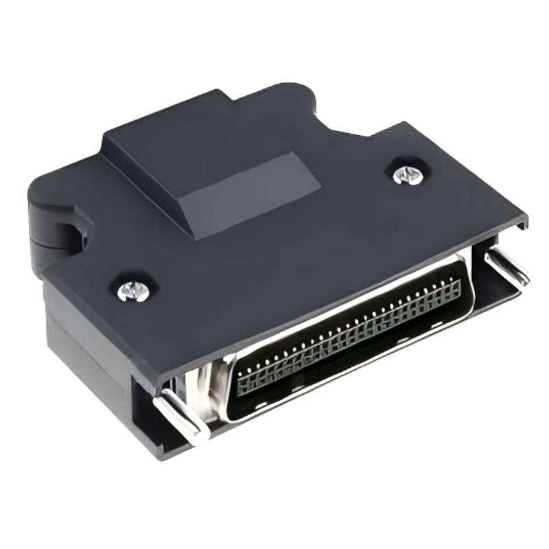
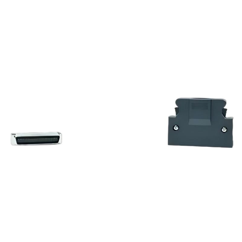
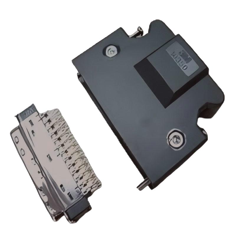
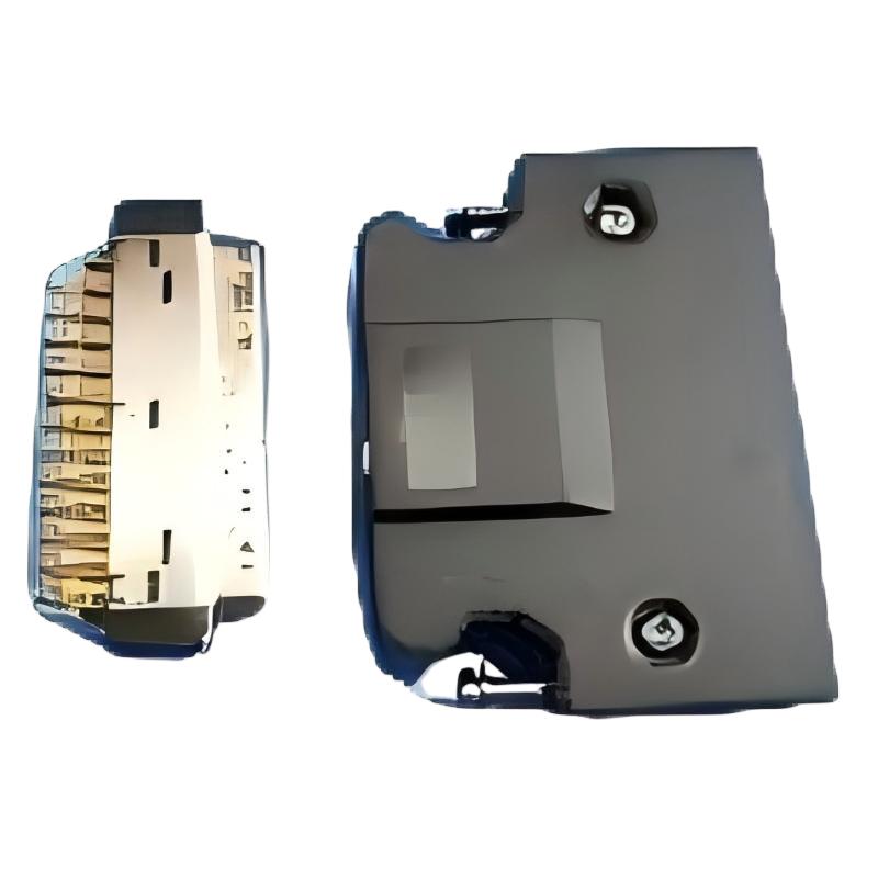
The Schneider VW3M1C12 Connector is an industrial automation connection component intended for use in equipment configurations where a suitable electrical or control-system connection is required. Connectors play an important role in industrial installations by providing a physical interface between compatible devices, cables, and system components.
In automation environments, reliable connections help maintain signal integrity, support equipment integration, and simplify maintenance. Selecting the correct connector is essential because components that look similar may have different contact arrangements, mechanical dimensions, electrical characteristics, or application requirements.
The Schneider VW3M1C12 has supplied dimensions of 86 × 74 × 52 mm and a listed weight of 0.05 kg. These specifications can assist with preliminary product identification, storage planning, and installation-space assessment. Before installation or replacement, the exact connector type, terminal arrangement, mating component, and intended function should be confirmed from the product label and applicable technical documentation.
For maintenance engineers, system integrators, and industrial spare-parts buyers, accurate model identification is particularly important when ordering connectors for existing machinery. A connector should not be selected based solely on its external dimensions or manufacturer name. Its interface and electrical characteristics must match the intended application.
2. Technical Specifications
| Parameter | Specification |
|---|---|
| Brand | Schneider Electric |
| Model | VW3M1C12 |
| Product Type | Connector |
| Dimensions | 86 × 74 × 52 mm |
| Weight | 0.05 kg |
| Application | Industrial automation equipment connections, subject to verification |
| Connector Configuration | Confirm from the exact product documentation |
| Contact Arrangement | Verify before installation |
| Electrical Ratings | Confirm the specified voltage and current limits |
| Mating Components | Identify the approved matching connector or equipment interface |
| Installation Requirements | Follow the applicable assembly and connection instructions |
| System Compatibility | Verify against the connected equipment and system configuration |
The dimensions and weight above are the supplied product specifications. The exact connector design, pin assignment, contact type, electrical ratings, and supported equipment should be verified before use rather than inferred from the model number alone.
3. Function and Working Principle
A connector provides a physical interface that allows compatible electrical or electronic components to be joined. Depending on its design, it may connect power conductors, control signals, communication lines, or other specified circuits.
The precise function of the Schneider VW3M1C12 depends on its documented design and the equipment for which it is intended. The product designation alone does not establish its pinout, electrical capacity, or specific system role.
3.1 Establishing a Physical Connection
A connector brings designated contacts together to create the intended electrical connection. Proper mating ensures that the contacts align correctly and that the connection is secured according to the manufacturer’s requirements.
Incorrect alignment, incomplete insertion, or an unsuitable mating component can cause poor contact or prevent the equipment from operating correctly.
3.2 Supporting Electrical Signal or Power Transfer
Depending on the connector’s design, its contacts may carry electrical power, control signals, or other specified connections. The permitted function and electrical limits must be established from the product’s technical specifications.
Users should never assume that a connector designed for one circuit can safely be used for another simply because the physical dimensions appear suitable.
3.3 Maintaining Connection Reliability
A properly selected and installed connector helps maintain consistent contact between compatible components. Secure assembly, suitable environmental protection, and correct cable preparation can reduce the risk of intermittent connections and mechanical damage.
3.4 Simplifying Equipment Maintenance
Connectors can make it easier to assemble, inspect, or replace designated parts of an industrial system. However, the maintenance procedure depends on whether the connector is designed for repeated mating, permanent installation, or a specific service application.
The approved handling and replacement procedure should be confirmed before work begins.
4. Role in Industrial Automation Systems
Industrial automation systems contain multiple electrical and electronic components that must be connected according to a defined design. Connectors help establish these connections and support the integration of equipment within control panels, machines, and other industrial installations.
4.1 Electrical Equipment Integration
A connector may provide the interface between compatible equipment and its associated wiring or accessories. Correct selection helps ensure that the physical connection matches the intended circuit and installation arrangement.
4.2 Control Cabinet Organization
Control cabinets often contain densely arranged components, wiring assemblies, and connection points. Selecting a connector that matches the required interface helps technicians organize connections and maintain access for inspection and service.
The supplied dimensions of 86 × 74 × 52 mm can be used for preliminary layout planning, subject to confirmation of the product’s actual mounting and clearance requirements.
4.3 Equipment Assembly
During machine assembly, designated connectors can simplify the connection of compatible subassemblies. Correct mating parts and approved assembly procedures are essential for achieving a reliable connection.
4.4 Maintenance and Replacement
A damaged or incorrectly matched connector may cause an electrical fault or prevent equipment from operating as intended. Accurate part identification helps maintenance personnel obtain the correct replacement and avoid unnecessary changes to the original system design.
4.5 System Reliability
Reliable connections are important for the overall performance of industrial equipment. Connector selection, correct installation, and periodic inspection help reduce avoidable connection-related failures.
5. Industrial Applications
The Schneider VW3M1C12 may be considered for industrial equipment where the exact connector model is specified and its documented characteristics match the installation requirements.
5.1 Industrial Machinery
Industrial machines use connectors to join compatible electrical assemblies, control components, and wiring interfaces. The suitability of the VW3M1C12 depends on the specific machine design and approved connection arrangement.
5.2 Automation Control Panels
Control panels require properly matched connection components to support organized wiring and maintainable equipment layouts. Connector selection should account for available space, contact configuration, and electrical requirements.
5.3 Drive and Motor Equipment
Some industrial drive and motor installations use dedicated connectors for designated power, feedback, or control interfaces. Before considering the VW3M1C12 for such an application, verify that its documented function and contact arrangement match the equipment requirements.
5.4 Manufacturing and Assembly Equipment
Automated production equipment often contains multiple interconnected assemblies. Correct connectors can help maintain the intended electrical connections and make approved maintenance procedures more manageable.
5.5 Industrial Equipment Servicing
During repairs, technicians may need to replace damaged or worn connection components. Using the correct model helps preserve the original equipment arrangement and reduces the risk of incompatible substitutions.
5.6 Equipment Modernization
When modifying or upgrading an automation system, existing connectors may need to be checked for compatibility with new components. The VW3M1C12 should be used only after verifying its interface, electrical limits, mechanical fit, and suitability for the revised configuration.
These examples describe potential industrial environments for appropriately specified connectors. They do not confirm that the VW3M1C12 is compatible with every application listed.
6. Installation and System Integration
Correct installation helps prevent contact problems, mechanical damage, and electrical faults. The following checklist provides general guidance; the product-specific instructions and the connected equipment’s requirements take precedence.
Step 1: Verify the Product Model
Confirm that the product label or packaging identifies the connector as Schneider VW3M1C12. Compare the model number with the equipment documentation, spare-parts list, or original component.
Do not substitute another connector solely because its dimensions appear similar.
Step 2: Confirm the Intended Function
Determine what the connector is designed to connect and identify the corresponding mating component. Verify the required contact arrangement and the electrical characteristics of the intended circuit.
Step 3: Isolate the Equipment
Before handling or installing the connector, place the equipment in a safe state and isolate the relevant power sources according to the site’s approved procedures. Verify that the circuit is safe to work on before proceeding.
Follow lockout/tagout requirements where applicable.
Step 4: Inspect the Connector
Examine the housing, contacts, locking features, and any associated cable interface for visible damage or contamination. Do not use a connector with cracked insulation, bent contacts, damaged locking features, or other defects that could affect safe operation.
Step 5: Prepare the Connection
Prepare conductors or mating components only according to the approved installation instructions. Use the specified tools and termination method where applicable.
Do not guess the pin assignment, conductor size, stripping length, or tightening torque.
Step 6: Align and Assemble
Align the connector with the designated mating interface and follow the specified assembly procedure. Avoid excessive force, which can damage the housing or contacts.
If the connector does not fit correctly, stop and recheck the model, orientation, and mating component.
Step 7: Secure the Connection
Engage the specified locking or retention mechanism, if provided. Confirm that the connection is seated correctly and that any connected cable is supported without excessive tension.
Step 8: Inspect and Test
Before restoring operation, inspect the completed installation and verify the connection according to the applicable procedure. Once the equipment is returned to service, check relevant diagnostic information and confirm that the connected system operates as intended.
7. Common Problems and Troubleshooting
Connector-related faults can result from incorrect selection, poor assembly, damaged contacts, environmental exposure, or problems elsewhere in the connected circuit.
| Symptom | Possible Causes | Recommended Checks |
|---|---|---|
| Connector cannot be mated | Incorrect model, incompatible mating component, or damaged housing | Verify the part number and inspect both mating interfaces |
| Intermittent electrical connection | Loose assembly, damaged contacts, or mechanical stress | Isolate the equipment and inspect the contacts and retention mechanism |
| Equipment does not operate after connection | Incorrect wiring, incompatible interface, or another system fault | Check the approved wiring diagram and diagnostic information |
| Visible contact damage | Improper handling, misalignment, or excessive force | Replace or service the component according to the approved procedure |
| Connector becomes loose | Incorrect assembly, damaged locking features, or cable tension | Inspect the retention mechanism and cable support |
| Corrosion or contamination is present | Unsuitable environmental conditions or inadequate protection | Assess the environment and follow the approved cleaning or replacement procedure |
| Fault persists after replacement | The cause may be in the wiring, mating component, or connected equipment | Inspect the complete circuit and related system components |
7.1 Check Mechanical Fit
Verify the connector model and the matching interface. Inspect the housing and locking features for damage. A connector should not be forced into place if the mating parts do not align correctly.
7.2 Inspect Contact Condition
With the equipment safely isolated, examine accessible contacts for deformation, corrosion, or contamination. Follow the manufacturer’s instructions for inspection and cleaning. Replace components that cannot be restored to the required condition through an approved procedure.
7.3 Verify Wiring and Contact Assignment
If the connected equipment fails to operate, compare the wiring with the approved circuit diagram. Confirm that the contact assignment matches the intended application.
Never determine pin assignments by trial and error or by relying on the connector’s external appearance.
7.4 Review the Connected Equipment
A connector fault may be mistaken for a problem with a controller, drive, sensor, or other component. Review diagnostic information and inspect the full connection path before replacing additional equipment.
7.5 Replace Defective Components
If the connector is damaged or fails the required inspection, use a verified compatible replacement. After installation, perform the required checks before returning the system to normal operation.
8. Preventive Maintenance and Reliability
A preventive maintenance program can help identify connector problems before they cause equipment interruptions.
- Inspect housings and contacts: Look for cracks, deformation, corrosion, or contamination during scheduled maintenance.
- Check connection security: Verify that the connector is properly seated and that its retention features function as intended.
- Protect against mechanical stress: Prevent cables from pulling on the connector or placing excessive force on the mating interface.
- Maintain suitable environmental conditions: Follow the product’s requirements for temperature, moisture, dust, and other environmental factors.
- Use correct handling methods: Avoid forcing, twisting, or improperly disassembling the connector.
- Keep spare-parts records: Record the exact model number and relevant equipment association.
- Document replacement work: Track maintenance dates, identified defects, and the parts installed.
- Follow approved procedures: Use the manufacturer’s instructions and site safety requirements for inspection and testing.
The appropriate inspection interval depends on the operating environment, equipment criticality, vibration, connection frequency, and site maintenance policy.
9. Compatible System Components
The exact compatible components for the VW3M1C12 should be established from its product documentation and the requirements of the equipment in which it will be installed.
| Component Category | Integration Considerations |
|---|---|
| Mating connector | Confirm the approved matching model and mechanical interface |
| Connected automation equipment | Verify that the equipment specifies or supports this connector |
| Cable assembly | Check the required cable type, termination, and connection arrangement |
| Electrical conductors | Confirm conductor specifications and termination requirements |
| Control cabinet or mounting assembly | Check available space, mechanical support, and required clearances |
| Power or control circuit | Verify the intended function, electrical ratings, and contact assignments |
| Maintenance spare parts | Ensure the replacement matches the original part number and application |
This table identifies component categories to review during integration. It does not confirm compatibility with any specific product model.
10. Replacement and Alternative Selection
Selecting a replacement connector requires more than matching its appearance or overall dimensions. The replacement must meet the electrical, mechanical, and application requirements of the original installation.
| Selection Factor | What to Verify |
|---|---|
| Exact model | Confirm Schneider VW3M1C12 |
| Dimensions | 86 × 74 × 52 mm |
| Weight | 0.05 kg |
| Connector interface | Match the required mating arrangement |
| Contact configuration | Verify the contact count and assignments |
| Electrical ratings | Confirm the permitted voltage, current, and other applicable limits |
| Mechanical retention | Check the locking and mounting arrangements |
| Environmental suitability | Verify that the connector meets the installation conditions |
| Equipment compatibility | Confirm suitability for the connected device and circuit |
| Product condition | Inspect the housing, contacts, and packaging before installation |
10.1 Selecting a Direct Replacement
The original model number is the preferred starting point when sourcing a replacement. Compare the complete part number and confirm that the replacement matches the original connector’s documented function.
If the original component is unavailable, consult the equipment documentation or an authorized technical specialist before selecting an alternative.
10.2 Evaluating Alternative Connectors
An alternative connector should be assessed for contact arrangement, electrical characteristics, mechanical fit, retention method, and environmental requirements. Similar dimensions alone do not demonstrate functional equivalence.
10.3 Replacement and Commissioning
After replacing a connector, inspect the assembly, verify the connection against the approved wiring documentation, and perform the required operational checks. Record the replacement in the maintenance history.
11. Key Benefits of Correct Connector Selection
Selecting the correct connector can support reliable connections and more efficient equipment maintenance.
Reliable physical connection: A correctly matched connector provides the intended interface between compatible components.
Improved integration: Appropriate mechanical and electrical compatibility helps maintain the designed system arrangement.
Practical identification: The VW3M1C12 model number, supplied dimensions, and listed weight provide useful information for product identification and inventory control.
Simplified maintenance: Accurate part identification can reduce delays when sourcing replacement components.
Reduced installation risk: Verifying the connector and mating interface helps prevent damage caused by incompatible parts or incorrect assembly.
Better troubleshooting: Correctly identified components help maintenance teams distinguish connector-related faults from problems elsewhere in the system.
These benefits depend on confirming the product’s exact specifications and using it within the limits defined for the intended application.
12. Technical FAQs
Q1: What is the Schneider VW3M1C12?
The Schneider VW3M1C12 is identified in the supplied product information as a connector. Its precise function and compatible equipment should be confirmed using the product label and applicable technical documentation.
Q2: What are the dimensions of the VW3M1C12?
The supplied dimensions are 86 × 74 × 52 mm.
Q3: How much does the connector weigh?
The supplied product weight is 0.05 kg.
Q4: What is the connector used for?
A connector provides a physical interface between compatible electrical or electronic components. The specific function of the VW3M1C12 depends on its documented design and intended application.
Q5: Can the VW3M1C12 be used with any Schneider Electric product?
No. Compatibility should be verified for the exact equipment model, mating interface, contact configuration, and electrical requirements.
Q6: What should be checked before installation?
Confirm the model number, intended function, matching connector, contact assignment, electrical ratings, and installation requirements. Ensure the equipment is in a safe state before handling the connector.
Q7: Why might a connector cause intermittent operation?
Potential causes include loose assembly, damaged contacts, contamination, corrosion, cable tension, or a fault in the connected circuit. Inspect the connection safely and follow the equipment’s diagnostic procedure.
Q8: Can a similar connector be used as a replacement?
Only if its mechanical interface, contact arrangement, electrical ratings, and application compatibility are verified. Similar dimensions or appearance are not sufficient.
Q9: How can connector failures be prevented?
Use the correct connector, follow the approved assembly procedure, protect the connection from mechanical stress and environmental damage, and inspect it during scheduled maintenance.
Q10: What should be done if the equipment still fails after connector replacement?
Review the wiring, mating component, connected equipment, and system diagnostics. The original fault may not have been caused by the connector alone.
13. Conclusion
The Schneider VW3M1C12 Connector is an industrial connection component with supplied dimensions of 86 × 74 × 52 mm and a listed weight of 0.05 kg. These specifications provide a useful starting point for product identification, storage planning, and replacement management.
Reliable operation depends on confirming the connector’s exact function, matching interface, contact arrangement, electrical ratings, and compatibility with the connected equipment. Correct installation, careful inspection, and systematic troubleshooting can help reduce connection-related faults and avoid unnecessary equipment downtime.
For industrial maintenance and spare-parts procurement, verify the complete model number and applicable technical requirements before installation or replacement. Selecting the correct connector helps preserve the intended system configuration and supports dependable industrial automation operation.