

ProductPRODUCT
Featured products
Contact Us
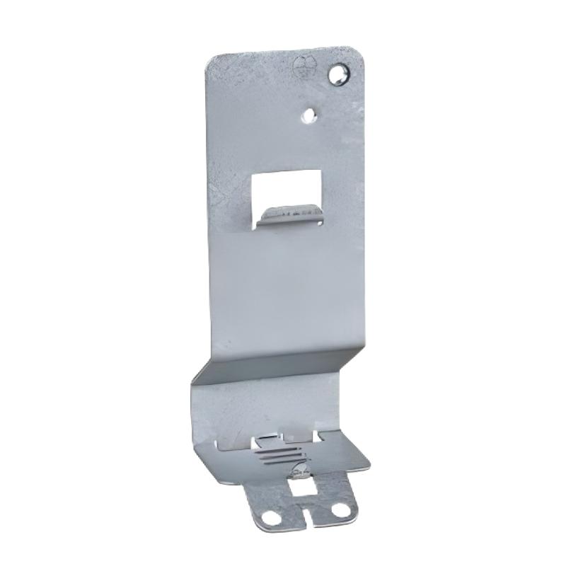
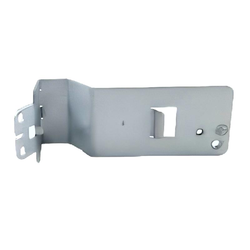
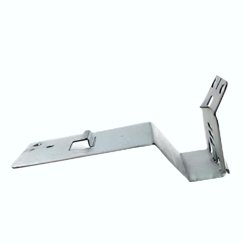
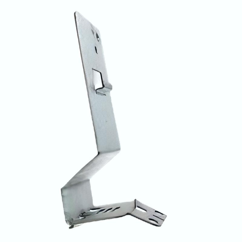
- Schneider
- VW3A9921
- Mounting Kit
- France
- 230 x 170 x 75 mm
- 0.075 kg
- Xiamen, China
- New & In Stock
- T/T, PayPal, Western Union
- 1 Year
- 1-3 Working Days
- DHL, UPS, TNT, FedEx and EMS.
- 24-Hour Service
- COO
- 4
Our advantage

Global Logistics
We have a 10-year logistics and express cooperation agreement, so our products can be shipped to any place in the world.

Brand new and original
Our products are imported in bulk from the place of origin. Because of the cooperative relationship, our products are all original and 100% new.

24-hour service
We provide 7*24 hours service to our customers. We will be there whenever you need us.

Price advantage
All our products are priced very favorably because we have our own warehouse and supply.
| Company Information | |||
| [email protected] | |||
| Mobile | +8615980777398 | ||
| +8615980777398 | |||
| 15980777398 |
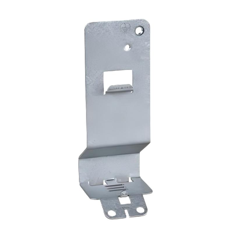
1. Product Overview
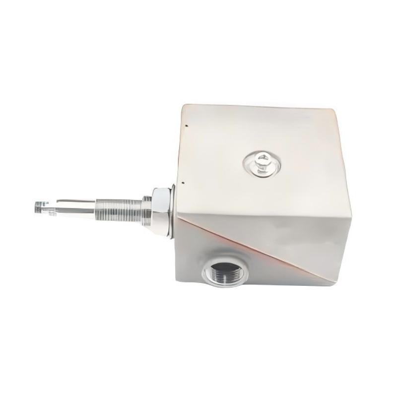
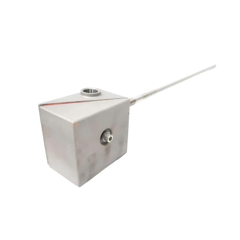
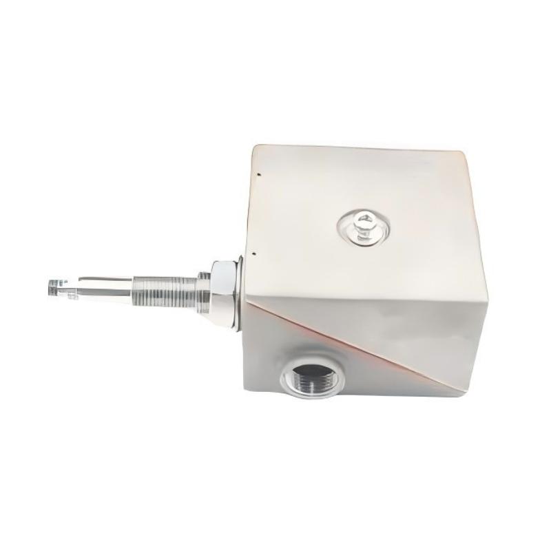
The Schneider VW3A9921 Mounting Kit is an industrial automation accessory intended to support the mechanical installation and integration of compatible equipment. Mounting kits are important in industrial control systems because they help establish the required mechanical arrangement, support secure equipment positioning, and simplify installation and maintenance.
With supplied dimensions of 230 × 170 × 75 mm and a weight of 0.075 kg, the VW3A9921 can be considered when evaluating installation space and equipment mounting requirements. Before purchasing or installing this kit, its exact components, intended application, mounting method, and compatibility with the target equipment should be confirmed using the product identification and applicable technical documentation.
The model number alone does not establish which specific drive, controller, enclosure, or other automation component the kit supports. Correct identification is essential to avoid mechanical incompatibility and unnecessary installation work.
2. Technical Specifications
| Parameter | Specification |
|---|---|
| Brand | Schneider Electric |
| Model | VW3A9921 |
| Product Type | Mounting Kit |
| Dimensions | 230 × 170 × 75 mm |
| Weight | 0.075 kg |
| Application | Mechanical mounting and equipment integration, subject to compatibility verification |
| Mounting Method | Confirm the approved installation procedure |
| Kit Contents | Verify against the product label and parts list |
| Compatible Equipment | Confirm the designated equipment models |
| Installation Requirements | Follow the applicable product documentation |
| Maintenance Requirements | Periodic inspection according to installation conditions |
The dimensions and weight above are the supplied product specifications. The exact kit contents, mounting orientation, fastening requirements, and supported equipment models should be verified before installation.
3. Function and Working Principle
A mounting kit provides the mechanical components needed to install, secure, or position compatible equipment. Depending on its design, a kit may include brackets, mounting plates, fasteners, supports, or other dedicated hardware.
The Schneider VW3A9921 should be used according to its specified purpose rather than treated as a universal mounting accessory. Its exact function and required installation arrangement must be established from the relevant documentation.
In a typical industrial installation, the mounting kit works by providing a defined mechanical interface between the equipment and its mounting location. Correct installation helps maintain the intended position and alignment of the equipment while reducing the risk of movement caused by normal operating conditions.
The following factors should be checked before use:
- Equipment compatibility: Confirm that the kit is intended for the exact equipment model.
- Mechanical dimensions: Verify the mounting points, available clearance, and installation space.
- Fastening requirements: Use the specified fasteners and tightening procedures.
- Mounting orientation: Follow the approved installation position.
- Environmental conditions: Check whether vibration, temperature, dust, or other conditions affect installation requirements.
- Required accessories: Confirm whether additional hardware is needed to complete the installation.
Correct mounting supports orderly equipment integration and makes future maintenance easier.
4. Role in Industrial Automation Systems
Industrial automation equipment must be mounted securely to support safe operation, organized wiring, and effective maintenance. Dedicated mounting accessories can help engineers implement the mechanical arrangement specified for a particular system.
4.1 Mechanical Equipment Support
A mounting kit provides the designated mechanical interface for compatible equipment. Correct installation helps maintain the intended position and prevents avoidable movement or misalignment.
4.2 Control Cabinet Organization
Mounting accessories can support orderly arrangements within electrical cabinets or equipment enclosures. Engineers should verify available space, required clearances, and access to terminals and connectors before installation.
4.3 Equipment Integration
Automation projects often combine drives, controllers, interface modules, and auxiliary components. A model-specific mounting kit may be required to install equipment according to the intended design.
4.4 Maintenance and Replacement
Correctly identifying the mounting kit helps technicians replace damaged or missing mechanical components without improvising unsupported mounting arrangements. Keeping model numbers and installation records also simplifies spare-parts management.
4.5 Installation Reliability
Incorrect mounting can lead to poor alignment, loose hardware, restricted access, or interference with adjacent equipment. Following the designated installation procedure helps reduce these risks.
5. Industrial Applications
The suitability of the VW3A9921 depends on its verified function and compatibility with the intended equipment. Potential environments in which dedicated industrial mounting kits are used include the following.
5.1 Motor Control Installations
Industrial motor control systems require equipment to be mounted according to specified mechanical and environmental requirements. Where the VW3A9921 is identified as the designated kit for a particular component, it should be installed according to the approved procedure.
5.2 Variable Speed Drive Systems
Drive installations may require dedicated mechanical accessories to support a specific mounting arrangement. Before using the VW3A9921 in a drive system, verify the supported drive model and any required clearance or ventilation provisions.
5.3 Industrial Control Cabinets
Control cabinets contain multiple electrical components that must be arranged to provide suitable access, wiring space, and thermal management. The supplied dimensions can assist preliminary space planning, but the actual mounting interface must be confirmed.
5.4 Automated Machinery
Manufacturing lines, packaging equipment, and material handling systems use mechanical mounting hardware to integrate control and electrical components into machine assemblies. Compatibility and environmental suitability should be checked for each installation.
5.5 Equipment Modernization and Repair
During maintenance or system upgrades, a mounting kit may be required to restore the original installation arrangement or accommodate an approved equipment configuration. Any modification should follow the equipment manufacturer’s instructions and the site’s change-control procedures.
These examples describe general applications for appropriately matched mounting hardware. They do not confirm that the VW3A9921 is suitable for every equipment category listed.
6. Installation and System Integration
Correct installation is important for maintaining mechanical stability and ensuring that the mounted equipment can operate as intended. The following workflow is a general checklist; the model-specific instructions take precedence.
Step 1: Verify the Product Model
Check the product label and confirm that the kit is identified as Schneider VW3A9921. Compare the model with the equipment documentation, bill of materials, or existing approved installation.
Step 2: Confirm Compatibility
Identify the equipment that the kit is intended to support. Verify mounting points, dimensions, orientation, required accessories, and any restrictions on the equipment combination.
Step 3: Isolate the Equipment
Before working on an electrical installation, place the equipment in a safe state and isolate relevant power sources according to the site’s lockout/tagout procedure. Follow all applicable electrical and mechanical safety requirements.
Step 4: Inspect the Kit Contents
Check the supplied components against the expected parts list. Inspect brackets, plates, fasteners, and other hardware for visible damage, deformation, corrosion, or missing parts.
Step 5: Prepare the Mounting Location
Ensure that the mounting surface or enclosure is suitable for the intended installation. Check available space, accessibility, required clearances, and any specified ventilation or environmental requirements.
Step 6: Position the Mounting Components
Arrange the kit components according to the approved mounting instructions. Confirm the correct orientation and alignment before tightening any fasteners.
Step 7: Secure the Assembly
Use the specified fastening hardware and tightening procedure. Do not substitute fasteners or apply an assumed tightening torque without confirming the applicable requirements.
Step 8: Check Clearances and Access
After installation, verify that the equipment is properly positioned and that terminals, connectors, service panels, and ventilation openings remain accessible as required.
Step 9: Complete the Installation Inspection
Check the assembled mounting arrangement for loose hardware, interference, misalignment, or other visible issues. Restore power only after the installation has passed the required safety and commissioning checks.
Step 10: Document the Installation
Record the mounting kit model, associated equipment, and any relevant installation details. Documentation helps maintenance teams identify the correct spare parts and preserve the approved equipment arrangement.
7. Common Problems and Troubleshooting
Mounting-related problems can result from incorrect part selection, missing hardware, unsuitable installation surfaces, or an incorrect assembly procedure.
| Symptom | Possible Cause | Recommended Check |
|---|---|---|
| Kit does not fit the equipment | Incorrect model or incompatible mounting interface | Verify the kit model and approved equipment pairing |
| Mounting holes do not align | Incorrect orientation, dimensions, or component selection | Compare the assembly with the installation drawing |
| Hardware is missing | Incomplete kit or incorrect parts identification | Check the supplied contents against the parts list |
| Assembly feels loose | Incorrect fastening or unsuitable hardware | Inspect fasteners and follow the specified tightening procedure |
| Equipment interferes with adjacent components | Insufficient clearance or incorrect positioning | Review the cabinet layout and approved mounting arrangement |
| Installation restricts ventilation or service access | Incorrect placement or layout planning | Check clearance and accessibility requirements |
| Corrosion or visible deformation appears | Environmental exposure or mechanical damage | Assess the installation conditions and replace unsuitable parts |
| Problem persists after reassembly | Incorrect kit, damaged mounting surface, or wider mechanical issue | Recheck compatibility and inspect the complete mounting arrangement |
7.1 Verify the Kit Model
A mounting kit may look similar to another accessory while having different mounting points or intended uses. Check the complete part number and the supported equipment configuration before proceeding.
7.2 Check Alignment and Fasteners
Misaligned holes, loose fasteners, or incorrect hardware can affect the stability of the installation. Compare the assembly with the approved instructions and replace damaged components as necessary.
7.3 Inspect the Mounting Surface
The mounting surface must be appropriate for the intended equipment and installation conditions. Check for deformation, damage, or other issues that could prevent secure installation.
7.4 Review Equipment Clearances
Confirm that the mounting arrangement does not obstruct ventilation, cable routing, access panels, or other equipment. Correct any layout problems before commissioning.
7.5 Avoid Unauthorized Modifications
Do not drill additional holes, bend brackets, or alter mounting components unless an approved engineering procedure permits the modification. Unapproved changes may affect mechanical integrity or equipment compatibility.
8. Preventive Maintenance and Reliability
Routine inspection helps maintain the integrity of mounted industrial equipment and can reveal problems before they cause interruptions.
- Inspect fasteners: Check for looseness, missing hardware, and visible damage according to the maintenance schedule.
- Check mechanical alignment: Confirm that the mounted equipment remains in its intended position.
- Look for corrosion: Inspect exposed components for signs of deterioration where environmental conditions may be a concern.
- Review surrounding clearances: Ensure that later equipment changes have not obstructed ventilation or service access.
- Inspect for vibration-related issues: Where vibration is present, check for movement, wear, or loosening in accordance with approved procedures.
- Maintain parts records: Record the kit model and associated equipment in the maintenance inventory.
- Use approved replacements: Replace damaged components with the specified parts or a documented equivalent.
Inspection intervals should reflect the operating environment, equipment criticality, and site maintenance policy.
9. Compatible System Components
The following component categories may be relevant when evaluating the VW3A9921. They do not confirm compatibility with any specific model.
| Component Category | Verification Requirement |
|---|---|
| Variable speed drive or motor control equipment | Confirm the exact supported model and mounting requirements |
| Industrial controller or interface equipment | Verify whether the kit is designated for the intended device |
| Control cabinet or enclosure | Check available space, mounting points, and required clearances |
| Mounting plate or support structure | Confirm mechanical dimensions and load requirements |
| Fasteners and fixing hardware | Use the specified types and sizes |
| Adjacent electrical components | Ensure that the mounting arrangement preserves required clearance and service access |
Compatibility should be confirmed from the complete equipment configuration and approved mounting documentation rather than inferred from the Schneider Electric brand alone.
10. Replacement and Alternative Selection
When replacing the Schneider VW3A9921 Mounting Kit, evaluate the mechanical and installation requirements before selecting an alternative.
| Selection Factor | What to Verify |
|---|---|
| Exact model | Confirm VW3A9921 against the original installation records |
| Dimensions | The supplied dimensions are 230 × 170 × 75 mm |
| Weight | The supplied product weight is 0.075 kg |
| Mounting interface | Compare hole locations, attachment points, and mechanical arrangement |
| Kit contents | Verify the required brackets, fasteners, and other components |
| Equipment compatibility | Confirm the intended device model and approved configuration |
| Material and condition | Inspect for damage, corrosion, or deformation |
| Installation requirements | Check orientation, clearances, and fastening procedures |
| Replacement suitability | Confirm functional and mechanical equivalence before substitution |
A mounting kit with similar dimensions is not necessarily interchangeable with the VW3A9921. Differences in attachment points, component design, or intended equipment can prevent correct installation. Use an alternative only after its suitability has been verified.
11. Key Benefits of Correct Mounting Kit Selection
Selecting the appropriate mounting kit supports several general objectives in industrial automation.
Secure equipment installation: Correctly matched hardware helps establish the intended mechanical arrangement.
Efficient space planning: The supplied dimensions of 230 × 170 × 75 mm provide preliminary information for installation layout planning.
Organized system integration: Dedicated mounting components can help maintain an orderly arrangement of compatible equipment.
Simplified maintenance: Accurate identification of the mounting kit makes it easier to source the correct replacement parts.
Reduced installation errors: Verifying mounting points and kit contents before assembly helps prevent avoidable rework.
These benefits depend on confirming the exact application, using the correct hardware, and following the approved installation procedure.
12. Technical FAQs
Q1: What is the Schneider VW3A9921?
The Schneider VW3A9921 is identified in the supplied product information as a mounting kit for industrial equipment installation. Its exact purpose and supported equipment models should be confirmed from the product documentation.
Q2: What are the dimensions of the VW3A9921?
The supplied dimensions are 230 × 170 × 75 mm.
Q3: How much does the VW3A9921 weigh?
The supplied product weight is 0.075 kg.
Q4: Which equipment is compatible with this mounting kit?
Compatibility depends on the kit’s intended application and mechanical interface. Confirm the exact supported equipment model before installation or replacement.
Q5: Does the mounting kit include all required fasteners?
The supplied information does not establish the exact kit contents. Check the product parts list and packaging before beginning installation.
Q6: Can the VW3A9921 be used as a universal mounting accessory?
It should not be treated as universal. Mounting points, dimensions, orientation, and equipment compatibility must be verified for the intended installation.
Q7: What should be checked before installing the kit?
Confirm the model number, kit contents, mounting interface, required fasteners, installation orientation, and available clearances. Inspect all components for damage before use.
Q8: Can a similar mounting kit be used as a replacement?
Only when mechanical fit, intended function, fastening requirements, and equipment compatibility have been verified. Similar dimensions alone do not establish equivalence.
Q9: What should be done if the equipment does not fit the mounting kit?
Stop the installation and recheck the kit model, equipment model, orientation, and mounting drawing. Do not force the components together or modify the kit without an approved procedure.
13. Conclusion
The Schneider VW3A9921 Mounting Kit is an industrial automation accessory identified by the supplied dimensions of 230 × 170 × 75 mm and weight of 0.075 kg. Selecting the correct mounting hardware is important for secure equipment installation, organized system integration, and efficient maintenance.
Before purchasing or installing the VW3A9921, confirm its exact application, kit contents, mounting interface, and compatibility with the intended equipment. Careful inspection, correct fastening, appropriate clearance management, and documented maintenance procedures help reduce avoidable installation problems and support reliable industrial automation systems.