

ProductPRODUCT
Featured products
Contact Us
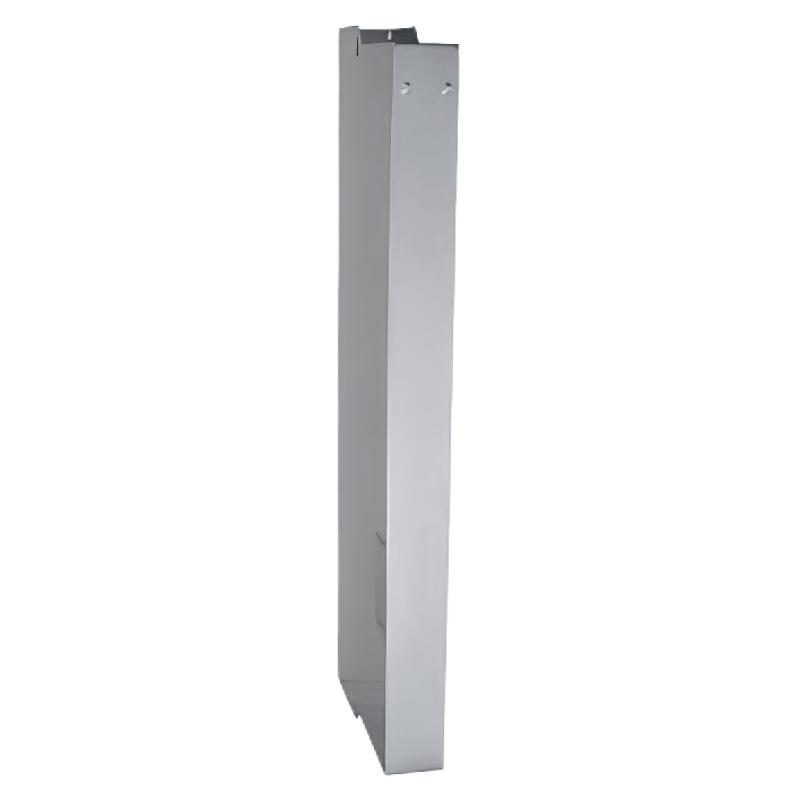
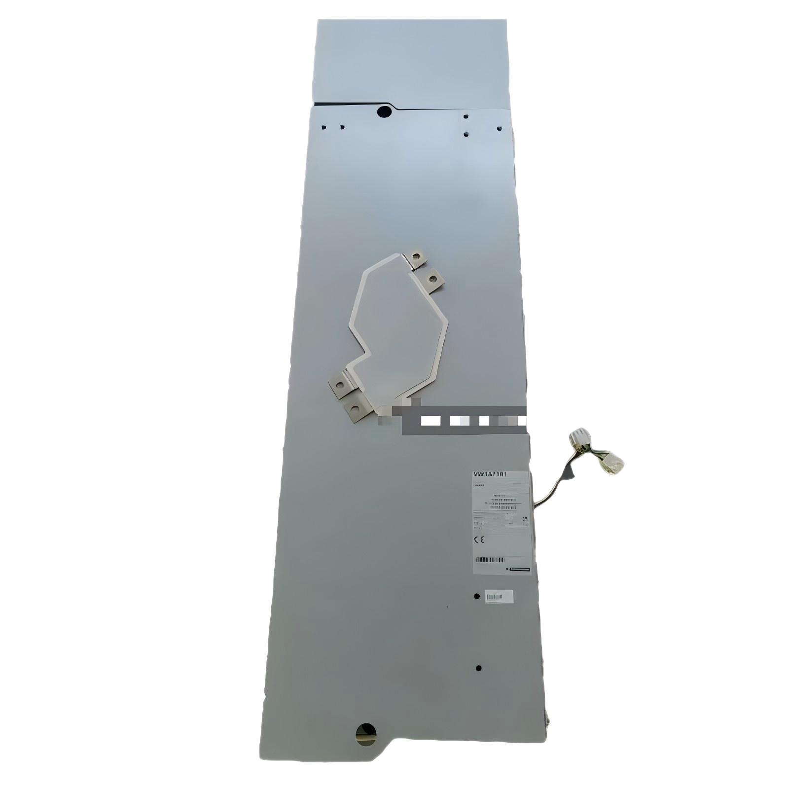
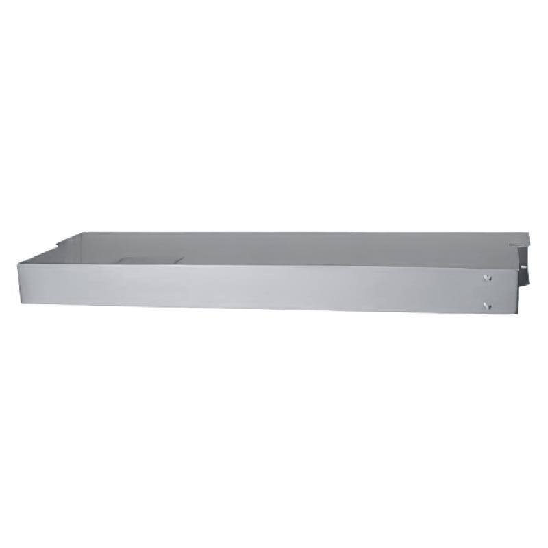
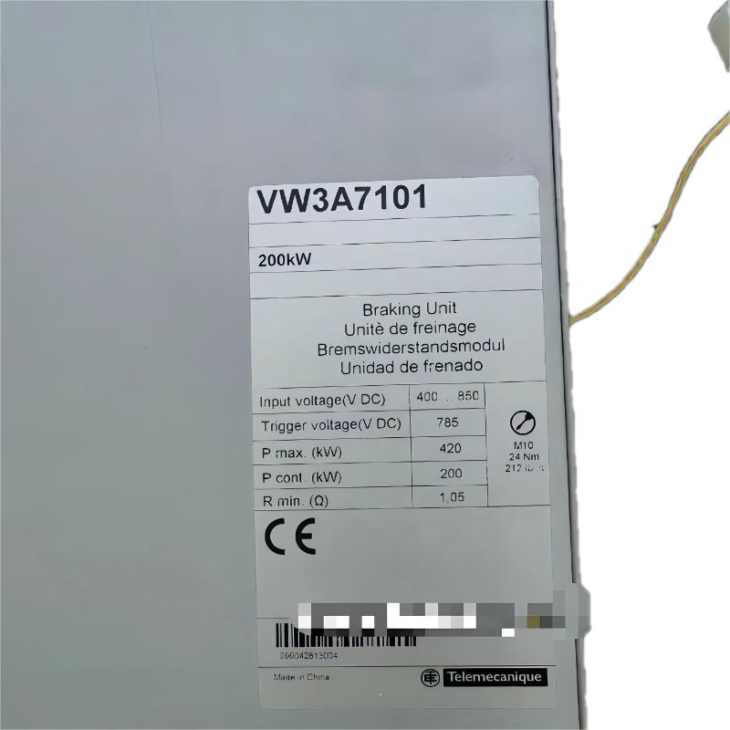
- Schneider
- VW3A7101
- Resistive Braking Unit
- France
- 3700 x 1100 x 490 mm
- 30 kg
- Xiamen, China
- New & In Stock
- T/T, PayPal, Western Union
- 1 Year
- 1-3 Working Days
- DHL, UPS, TNT, FedEx and EMS.
- 24-Hour Service
- COO
- 4
Our advantage

Global Logistics
We have a 10-year logistics and express cooperation agreement, so our products can be shipped to any place in the world.

Brand new and original
Our products are imported in bulk from the place of origin. Because of the cooperative relationship, our products are all original and 100% new.

24-hour service
We provide 7*24 hours service to our customers. We will be there whenever you need us.

Price advantage
All our products are priced very favorably because we have our own warehouse and supply.
| Company Information | |||
| [email protected] | |||
| Mobile | +8615980777398 | ||
| +8615980777398 | |||
| 15980777398 |
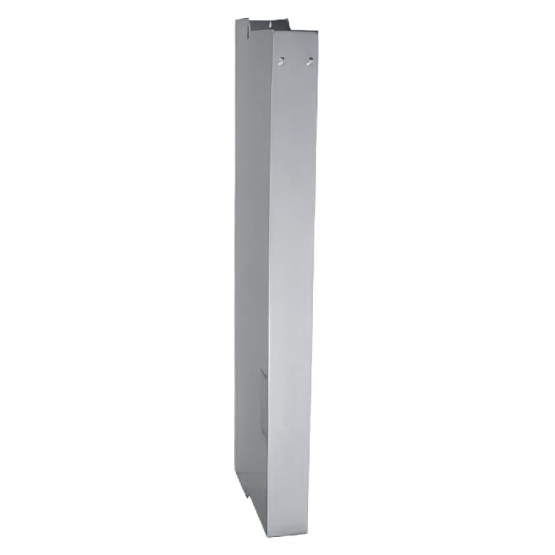
1. Product Overview
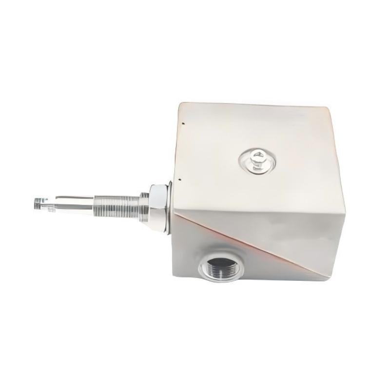
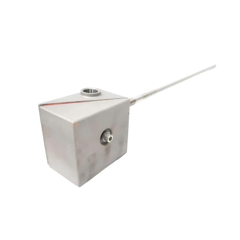
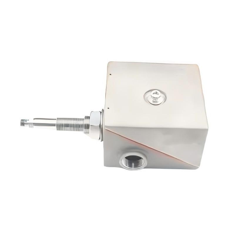
The Schneider Electric VW3A7101 Resistive Braking Unit is an industrial drive-related component identified for applications involving resistive braking in motor control systems. Resistive braking is commonly used with compatible variable frequency drives when a motor must decelerate more rapidly or when the drive system needs to manage regenerated electrical energy during braking.
During deceleration, an electric motor can act as a generator and return energy to the drive’s DC bus. If the drive cannot return this energy to the supply or otherwise absorb it, the DC bus voltage may rise. In a compatible braking arrangement, a braking unit controls the connection of a braking resistor so that excess electrical energy can be converted into heat.
The VW3A7101 is supplied with listed dimensions of 3700 × 1100 × 490 mm and a weight of 30 kg. These values should be checked against the physical product label and dimensional drawing before installation or transport, particularly because the listed dimensions are unusually large relative to the stated weight for a braking unit.
The exact electrical ratings, supported drive models, braking resistor requirements, duty cycle, and connection arrangement must be confirmed using the model-specific technical documentation. The product name alone does not establish whether the VW3A7101 is a standalone braking unit, an assembly, or a component requiring additional braking hardware.
2. Technical Specifications
| Parameter | Specification |
|---|---|
| Brand | Schneider Electric |
| Model | VW3A7101 |
| Product Type | Resistive Braking Unit |
| Product Category | Industrial motor drive accessory |
| Dimensions | 3700 × 1100 × 490 mm |
| Weight | 30 kg |
| Primary Application | Resistive braking in a compatible drive system |
| Braking Method | Dissipation of braking energy through a compatible resistor arrangement, subject to system design |
| Rated Voltage | Verify from model-specific documentation |
| Rated Current | Verify from model-specific documentation |
| Braking Power | Verify from model-specific documentation |
| Braking Resistor Requirements | Confirm the required resistance, power rating, and permitted duty cycle |
| Compatible Drives | Verify the exact supported drive models |
| Cooling Requirements | Follow the applicable installation instructions |
| Mounting Requirements | Confirm the approved mounting arrangement and physical dimensions |
| Protection Requirements | Follow the drive and braking system specifications |
The dimensions and weight above are the supplied product specifications. Confirm the dimensional information before planning the installation. Electrical ratings and compatibility details must also be verified before commissioning.
3. Function and Working Principle
A resistive braking system helps manage energy generated when a motor decelerates. Its operation depends on the drive’s braking circuitry, the braking unit where applicable, and the correctly matched braking resistor.
3.1 Energy Generation During Deceleration
When a motor slows down, its mechanical energy may be converted into electrical energy. In a drive system capable of regenerative operation, this energy can return to the drive’s DC bus.
If the energy is not returned to the supply or absorbed elsewhere, the DC bus voltage may increase. Excessive voltage can trigger a drive fault or prevent the intended deceleration sequence from completing.
3.2 Braking Unit Operation
In a compatible braking arrangement, a braking unit monitors the relevant electrical condition and controls the connection of a braking resistor. When braking energy needs to be dissipated, the resistor converts electrical energy into heat.
The exact control method and switching behavior depend on the braking unit and drive architecture. The VW3A7101’s specific operating principle and required companion components should be confirmed from its technical documentation.
3.3 Braking Resistor Requirements
The braking resistor must be matched to the drive and braking unit. Its resistance, power rating, thermal capacity, and duty cycle affect braking performance and system safety.
An unsuitable resistor may cause overheating, insufficient braking performance, or damage to the drive system. Never select a resistor based only on physical appearance or nominal power without checking the approved specifications.
3.4 Braking System Integration
The braking unit, resistor, drive, motor, protective devices, and wiring form an integrated system. Correct selection and configuration are necessary to achieve the intended deceleration behavior while keeping electrical and thermal conditions within permitted limits.
The VW3A7101 should only be used in the arrangement specified by the manufacturer for the intended drive.
4. Role in Industrial Automation Systems
Industrial automation systems frequently use variable speed drives to control the speed and deceleration of motors. In applications with high inertia, frequent stopping, or demanding deceleration requirements, a compatible braking arrangement may be needed to manage energy generated by the motor.
Controlled Motor Deceleration
A suitable resistive braking system can help a drive decelerate a motor according to the configured stopping profile, provided the system is correctly rated for the mechanical load and operating duty.
DC Bus Voltage Management
When regenerative energy cannot be returned to the supply, a compatible braking system can help prevent excessive DC bus voltage by dissipating the relevant energy through a braking resistor.
Process and Machine Coordination
Braking performance can affect machine cycle time, positioning, and coordination between equipment. The braking system must be designed according to the application’s mechanical and electrical requirements.
Equipment Reliability
Correct braking system selection can reduce avoidable drive trips caused by excessive regenerative energy. It does not replace proper drive sizing, mechanical braking where required, protective devices, or safe machine design.
5. Industrial Applications
The VW3A7101 may be evaluated for applications requiring a compatible resistive braking arrangement. Its suitability depends on verified ratings and approved drive compatibility.
5.1 Material Handling Equipment
Conveyors and other material handling machines may need controlled deceleration to manage moving loads. A suitable braking system can help the drive handle regenerated energy during stopping.
5.2 Industrial Machinery
Production equipment with frequent acceleration and deceleration may require braking energy management. The braking unit and resistor must be selected according to the motor, drive, inertia, and operating cycle.
5.3 Hoisting and Lifting Systems
Lifting equipment can involve substantial mechanical energy and safety requirements. A resistive braking unit alone must not be assumed to provide the complete stopping or holding function. The overall design must include the required mechanical brakes, safety circuits, and approved drive configuration.
5.4 Centrifugal Equipment
Certain high-inertia machines, including selected fans and rotating process equipment, can return energy to the drive during deceleration. The braking arrangement should be sized for the actual load and stopping frequency.
5.5 Drive System Modernization
During drive replacement or machine upgrades, the braking system may need to be reviewed alongside the motor, drive, resistor, and protective devices. The VW3A7101 should only be introduced after its compatibility and required companion components have been verified.
These examples describe general applications for appropriately selected resistive braking systems. They do not confirm that the VW3A7101 is suitable for every application listed.
6. Installation and System Integration
Installation should be performed by qualified personnel using the applicable Schneider Electric documentation and site electrical safety procedures.
Step 1: Verify the Model and Dimensions
Confirm that the product label identifies the component as VW3A7101. Compare the part number and supplied dimensions with the equipment drawings and original component.
Because the listed dimensions are 3700 × 1100 × 490 mm, verify the measurements carefully before planning transport, lifting, or mounting. Do not assume that the dimensions represent the component’s actual installed envelope without checking the dimensional drawing.
Step 2: Isolate the Equipment
Stop the drive and isolate all relevant power sources before installation or removal. Follow the site’s lockout/tagout procedures, observe the manufacturer’s specified discharge time, and verify that the equipment is in a safe, de-energized state before handling electrical connections.
Step 3: Confirm Electrical Compatibility
Verify the braking unit’s rated voltage, current capacity, permitted braking power, and supported drive models. Confirm whether additional braking circuitry or a separately specified resistor is required.
Do not determine compatibility from the product name or physical dimensions alone.
Step 4: Verify the Braking Resistor
Confirm the specified resistance, power rating, thermal capacity, and duty cycle for the intended drive and braking unit. Ensure that the resistor is installed in an appropriate location with the required heat dissipation and protection.
Braking resistors can become very hot during operation. Follow the manufacturer’s clearance and temperature requirements.
Step 5: Plan Mounting and Cable Routing
Confirm the approved mounting arrangement, available space, mechanical support, ventilation, and access for maintenance. Verify that power cables and braking connections can be routed according to the installation requirements.
If the supplied dimensions are accurate, the required installation space may be substantial and should be confirmed before equipment preparation begins.
Step 6: Complete Electrical Connections
Connect the drive, braking unit, resistor, and protective devices according to the approved wiring diagram. Verify conductor sizing, terminal torque, grounding, and cable insulation requirements.
Never improvise terminal assignments or connect a resistor with an unverified resistance value.
Step 7: Inspect the Installation
Before restoring power, inspect the mounting, wiring, protective covers, grounding, resistor location, and heat clearances. Ensure that all components are securely installed and that no tools or loose materials remain in the equipment area.
Step 8: Commission and Validate
Restore power according to the approved commissioning procedure. Check the drive’s configuration and diagnostic information, then validate deceleration behavior under controlled operating conditions.
Confirm that the braking system operates within its rated limits before returning the machine to normal service. Follow the machine’s risk assessment and safety procedures throughout commissioning.
7. Common Problems and Troubleshooting
A braking-related fault does not automatically mean the braking unit has failed. The cause may involve the drive, resistor, wiring, mechanical load, configuration, or operating duty.
| Symptom | Possible Causes | Recommended Checks |
|---|---|---|
| Drive reports a DC bus overvoltage fault during deceleration | Braking system not operating, unsuitable resistor, excessive regenerative energy, or incorrect configuration | Review drive diagnostics and verify the approved braking arrangement |
| Braking performance is insufficient | Incorrect braking settings, unsuitable resistor, or excessive mechanical load | Check drive parameters, resistor specifications, and application requirements |
| Braking resistor overheats | Excessive braking duty, incorrect resistance or power rating, or inadequate cooling | Verify resistor ratings, stopping frequency, ventilation, and operating conditions |
| Drive trips during frequent stops | Braking duty exceeds system capability or configuration is incorrect | Review deceleration time, load inertia, duty cycle, and system ratings |
| Braking unit is not detected or does not operate as expected | Incorrect wiring, incompatible hardware, power issues, or a component fault | Verify connections, compatibility, and diagnostic indications |
| Fault persists after component replacement | Root cause may be external to the braking unit | Check the drive, resistor, motor, mechanical load, wiring, and configuration |
7.1 Check Drive Diagnostics
Record the drive fault code, operating conditions, and deceleration settings before changing the configuration. Diagnostic information can help distinguish between an overvoltage condition, a wiring problem, and a braking system fault.
7.2 Inspect the Resistor and Wiring
With the equipment safely isolated, inspect the resistor connections and associated wiring for damage, loose terminals, or signs of overheating. Electrical measurements must be carried out by qualified personnel using suitable instruments and approved procedures.
7.3 Review Braking Duty
Frequent stops, short deceleration times, and high-inertia loads can increase braking energy and thermal demand. Compare the actual operating cycle with the drive, braking unit, and resistor ratings.
7.4 Check Cooling and Installation Conditions
Ensure that the braking components have the required ventilation and clearances. Investigate abnormal heating and confirm that the equipment is installed in an environment permitted by the manufacturer.
7.5 Confirm System Compatibility
If the fault remains, recheck the complete system configuration, including the drive model, braking unit, resistor, and protective devices. Replace components only after the fault has been investigated and the correct replacement has been identified.
8. Preventive Maintenance and Reliability
A planned maintenance program can help identify potential braking system problems before they interrupt production.
- Inspect electrical connections: Check for looseness, corrosion, damaged insulation, and signs of overheating.
- Monitor braking resistor temperature: Investigate abnormal heating and ensure that the resistor operates within its specified limits.
- Check mounting security: Confirm that the braking unit and associated components are securely installed.
- Maintain ventilation: Keep the required cooling paths and heat clearances unobstructed.
- Review drive diagnostics: Record recurring braking-related faults and investigate their causes.
- Verify operating duty: Compare stopping frequency and deceleration requirements with the approved system ratings.
- Maintain documentation: Keep wiring diagrams, model numbers, resistor specifications, and configuration records up to date.
- Follow electrical safety procedures: Isolate the equipment and verify a safe condition before inspection or maintenance.
Maintenance frequency should reflect the operating environment, braking duty, equipment criticality, and site maintenance policy.
9. Compatible System Components
The VW3A7101 must be evaluated as part of the complete braking system. The following component categories should be reviewed during engineering, commissioning, and replacement.
| Component Category | Compatibility Considerations |
|---|---|
| Variable speed drive | Confirm the exact supported drive model and braking interface |
| Braking resistor | Verify resistance, power rating, thermal capacity, and duty cycle |
| Electric motor | Assess motor characteristics, load inertia, and regenerative behavior |
| Power and braking cables | Confirm conductor sizing, insulation, routing, and connection requirements |
| Protective devices | Follow the approved protection scheme for the drive and braking circuit |
| Grounding system | Apply the specified protective grounding requirements |
| Mounting structure | Verify the actual dimensions, installed envelope, and mechanical support |
| Cooling and ventilation | Provide the required heat dissipation and clearances |
| Machine safety system | Confirm that the complete machine includes the required safety and mechanical braking functions |
This table identifies component categories to verify; it does not confirm compatibility with any specific drive or resistor model.
10. Replacement and Alternative Selection
When replacing a Schneider Electric VW3A7101 Resistive Braking Unit, confirm technical equivalence before considering price, availability, or physical dimensions.
| Selection Factor | What to Verify |
|---|---|
| Exact model | Confirm VW3A7101 and any applicable product revision |
| Braking function | Ensure the replacement performs the required braking function |
| Drive compatibility | Confirm the supported drive model and braking interface |
| Electrical ratings | Verify voltage, current, and permitted braking power |
| Resistor requirements | Confirm resistance, power rating, thermal capacity, and duty cycle |
| Operating conditions | Assess load inertia, stopping frequency, and deceleration requirements |
| Dimensions | Verify the supplied dimensions of 3700 × 1100 × 490 mm against the product drawing |
| Weight and mounting | Confirm the listed weight of 30 kg and the actual mounting requirements |
| Cooling requirements | Check ventilation and heat dissipation needs |
| Product condition | Assess authenticity, physical condition, testing status, and warranty where applicable |
The supplied dimensions should be confirmed before ordering because they are unusually large for a component with the stated weight. A physically similar braking unit is not necessarily electrically equivalent.
If the original model is unavailable, select an alternative only after verifying the complete braking system design and manufacturer-approved compatibility.
11. Key Benefits of Correct Braking System Selection
Selecting the correct resistive braking equipment can support reliable motor deceleration in suitable industrial drive applications.
Braking energy management: A properly matched resistive braking arrangement can dissipate regenerated energy when the drive cannot return it to the supply.
Controlled deceleration: Correctly configured braking equipment can help the drive achieve the required stopping profile within its rated limits.
Drive system integration: Matching the braking unit, resistor, and drive helps ensure that the system operates according to its intended design.
Maintenance planning: Accurate model identification and documented electrical ratings help maintenance teams select suitable replacement parts.
Installation preparation: Verified dimensions and weight support transport planning, mechanical support design, and safe installation.
These benefits depend on the verified specifications of the VW3A7101, correct system selection, and compliance with the manufacturer’s installation and safety requirements.
12. Technical FAQs
Q1: What is the Schneider Electric VW3A7101?
The VW3A7101 is identified as a Schneider Electric Resistive Braking Unit. Its precise electrical function, supported drive models, and required companion components should be confirmed from model-specific documentation.
Q2: What are the dimensions of the VW3A7101?
The supplied dimensions are 3700 × 1100 × 490 mm. These measurements should be checked against the product label or dimensional drawing before installation planning.
Q3: How much does the VW3A7101 weigh?
The supplied product weight is 30 kg.
Q4: What does a resistive braking unit do?
In a compatible drive system, a braking unit controls the dissipation of regenerated electrical energy through a braking resistor. This can help manage DC bus voltage during deceleration when energy cannot be returned to the supply.
Q5: Does the VW3A7101 require a separate braking resistor?
That depends on the product’s design and intended configuration. Confirm the required braking resistor and any companion components from the applicable technical documentation before installation.
Q6: Can the VW3A7101 be used with every Schneider Electric drive?
No. Compatibility depends on the drive model, electrical ratings, braking interface, resistor requirements, and approved system configuration.
Q7: Why can a drive trip during deceleration?
Potential causes include excessive regenerative energy, an unsuitable braking resistor, incorrect braking parameters, wiring problems, or a braking system fault. Review drive diagnostics and verify the complete braking arrangement.
Q8: What should be checked before installation?
Confirm the exact model, dimensions, electrical ratings, supported drive models, resistor requirements, mounting arrangement, wiring diagram, and cooling requirements. Follow the required electrical isolation and commissioning procedures.
Q9: Can a resistive braking unit replace a mechanical brake?
Not automatically. A resistive braking system manages electrical energy and motor deceleration; it does not necessarily provide the holding function or safety performance required from a mechanical brake. The complete machine design must meet the applicable safety requirements.
Q10: Can another braking unit replace the VW3A7101?
Only when the replacement’s electrical characteristics, drive compatibility, braking capacity, resistor requirements, and application suitability have been verified. Similar dimensions or product descriptions alone are not sufficient.
13. Conclusion
The Schneider Electric VW3A7101 Resistive Braking Unit is identified as an industrial drive-related component for applications involving resistive braking. Its supplied dimensions are 3700 × 1100 × 490 mm, and its listed weight is 30 kg. Because the dimensions are unusually large relative to the stated weight, the physical specifications should be verified against the actual product and dimensional drawing before procurement or installation.
For reliable operation, confirm the unit’s exact function, electrical ratings, compatible drive models, braking resistor requirements, and approved wiring arrangement. Correct system sizing, safe installation, appropriate heat management, and systematic troubleshooting are essential to dependable braking performance.
For industrial automation engineers, maintenance teams, and spare-parts purchasers, accurate product identification and compatibility verification are key to selecting the VW3A7101 for the intended application.