

ProductPRODUCT
Featured products
Contact Us
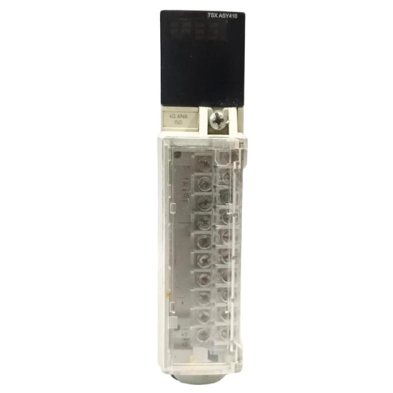
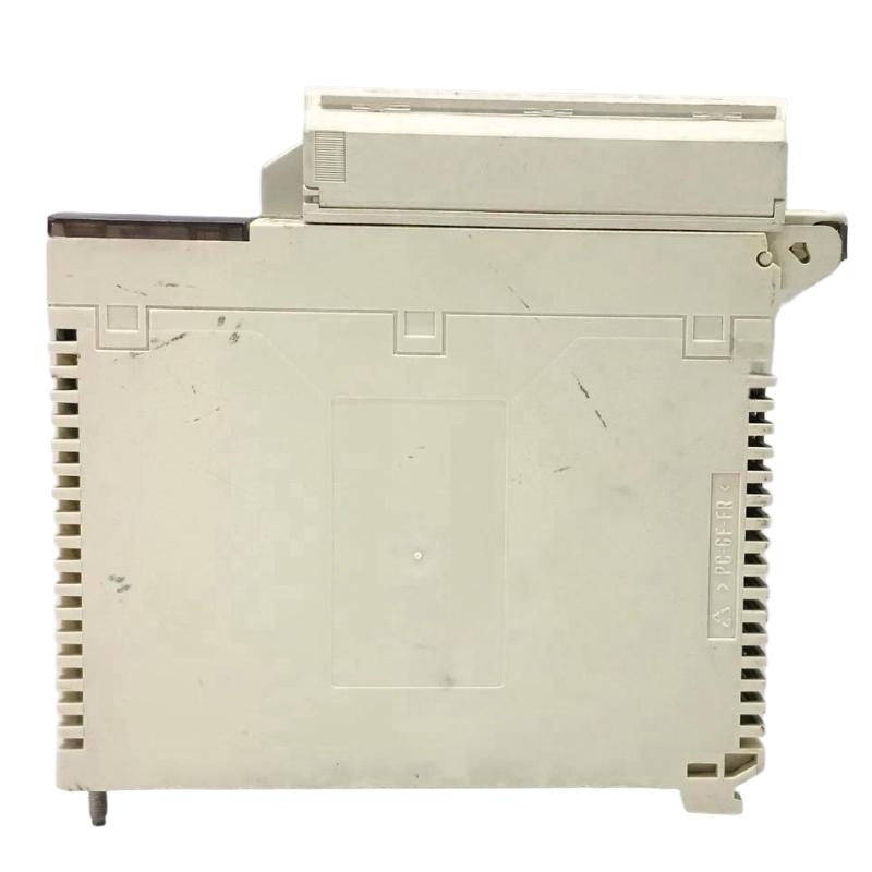
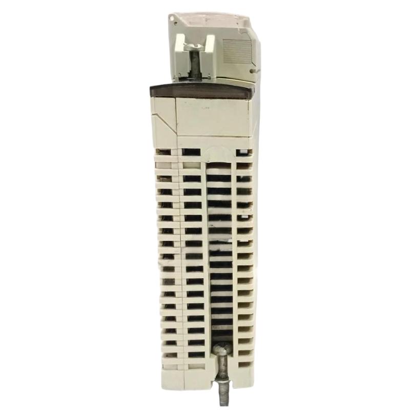
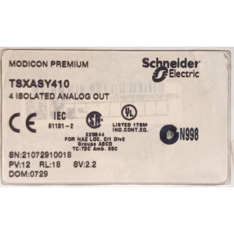
- Schneider
- TSXASY410
- Analog Output Module
- France
- 103 × 95 × 20 mm
- 0.35 kg
- Xiamen, China
- New & In Stock
- T/T, PayPal, Western Union
- 1 Year
- 1-3 Working Days
- DHL, UPS, TNT, FedEx and EMS.
- 24-Hour Service
- COO
- 4
Our advantage

Global Logistics
We have a 10-year logistics and express cooperation agreement, so our products can be shipped to any place in the world.

Brand new and original
Our products are imported in bulk from the place of origin. Because of the cooperative relationship, our products are all original and 100% new.

24-hour service
We provide 7*24 hours service to our customers. We will be there whenever you need us.

Price advantage
All our products are priced very favorably because we have our own warehouse and supply.
| Company Information | |||
| [email protected] | |||
| Mobile | +8615980777398 | ||
| +8615980777398 | |||
| 15980777398 |
1. Product Overview
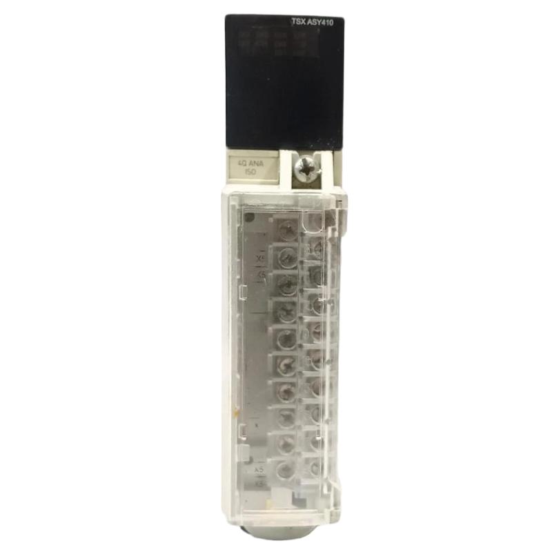
The Schneider TSXASY410 Analog Output Module is an industrial automation component designed to provide analog control signals from a programmable logic controller (PLC) to compatible field devices. Analog output modules play an important role in process automation because they allow controllers to adjust equipment operation through continuously variable signals rather than simple ON/OFF commands.
In industrial environments, analog output signals are commonly used to regulate motor speed references, control valve positions, adjust process setpoints, and interface with other equipment that accepts analog commands. By converting PLC control values into electrical output signals, an analog output module helps connect control logic with physical processes.
The Schneider TSXASY410 belongs to the TSX automation product designation. Before using this module in an existing installation, engineers should verify its exact platform compatibility, output-channel configuration, supported signal ranges, resolution, and wiring requirements against the relevant hardware documentation.
The supplied product information lists dimensions of 103 × 95 × 20 mm and a weight of 0.35 kg. These details can support preliminary equipment identification, spare-parts planning, and control cabinet assessments. The official dimensional drawing should be consulted before finalizing installation arrangements.
For industrial maintenance teams and automation system integrators, accurate module identification and correct configuration are essential to ensuring reliable analog control and avoiding incompatibility during replacement.
2. Technical Specifications
| Parameter | Specification |
|---|---|
| Brand | Schneider Electric |
| Model | TSXASY410 |
| Product Type | Analog Output Module |
| Product Category | PLC Analog I/O |
| Primary Function | Analog signal output and process control |
| Dimensions | 103 × 95 × 20 mm |
| Weight | 0.35 kg |
| Typical Application | Industrial automation and process control |
| System Integration | Compatible PLC hardware and supported field devices |
| Signal Ranges | Verify against the official module documentation |
| Output Resolution | Verify against the official module documentation |
| Electrical Isolation | Verify against the official module documentation |
| Supported Controller Platform | Confirm before installation |
Specification note: Dimensions and weight follow the supplied product information. Electrical characteristics, including the number of output channels, current or voltage ranges, resolution, accuracy, and load requirements, should be confirmed from the official TSXASY410 documentation rather than inferred from the model number.
3. Function and Working Principle
An analog output module allows a PLC to issue variable electrical commands to compatible industrial equipment. These commands represent control values calculated by the PLC application.
3.1 Converting PLC Commands into Analog Signals
The PLC executes its control program and determines the required output value. The analog output module converts the configured digital command into an electrical signal within its supported operating range.
A receiving device interprets that signal and adjusts its operation accordingly. Depending on the application, the command may represent a speed reference, valve position request, process setpoint, or another control parameter.
For example, a PLC may calculate that a pump should operate at a particular speed reference based on process demand. If the connected drive accepts the output signal provided by the module, the analog command can be used to request the required operating level.
The actual signal type and scaling must match the receiving device’s specifications.
3.2 Output Signal Processing
In a typical PLC system, the output process includes several stages:
- The PLC program calculates a control value.
- The controller transfers the configured value to the output channel.
- The module generates the corresponding electrical output.
- The receiving device interprets the signal.
- The controlled equipment responds to the command.
- Feedback signals, where available, allow the PLC to evaluate the result.
The module is only one part of this chain. Overall control performance depends on the controller, field wiring, signal conditioning, receiving equipment, and application logic.
3.3 Output Scaling
Output scaling converts an engineering command into the numeric value required by the module’s configured output range.
For example, a control program might translate a percentage command into an output value representing a requested operating level. The conversion must reflect the module’s supported range and the receiving equipment’s input requirements.
Incorrect scaling can cause equipment to operate below or above the intended setpoint. For this reason, commissioning should include verification of the PLC command, measured electrical output, and actual device response.
4. Role in Industrial Automation Systems
4.1 Process Regulation
Analog output modules are commonly used where process conditions require continuous adjustment. A PLC can calculate an output based on operator settings, process measurements, or a control algorithm and send the command to a compatible device.
Examples include regulating pressure, adjusting flow, or controlling a variable operating reference.
4.2 Drive and Motor Control Interfaces
Some industrial drives accept analog speed or torque references. Where the output signal is electrically compatible, an analog output module can provide the command value used by the drive.
The module should not be assumed to provide direct motor power. Motor power is supplied by the appropriate drive or power-control equipment.
4.3 Valve and Actuator Control
Compatible control valves and actuators may accept analog commands to regulate position or process output. In such installations, correct signal scaling, electrical compatibility, and fail-state design are important.
The TSXASY410 should only be connected to equipment whose signal requirements are supported by the verified module specifications.
4.4 Integration with Supervisory Systems
In a PLC-based architecture, analog output values may be determined by operator commands from an HMI or supervisory system. The PLC processes those commands according to the application logic and updates the appropriate output channel.
The HMI or supervisory software does not replace the need for correct output configuration and field-level electrical compatibility.
4.5 Equipment Maintenance
An analog output module can affect process stability when its output becomes inaccurate or unavailable. Correct fault diagnosis should consider the complete control path, including PLC logic, channel configuration, wiring, receiving devices, and the module itself.
5. Typical Industrial Applications
5.1 Manufacturing and Production Lines
Automated production equipment may require adjustable operating references for speed, position, pressure, or other process parameters. Analog outputs can provide commands to compatible devices as part of the PLC control strategy.
5.2 Water and Wastewater Treatment
Water treatment systems often use PLC control to regulate pumping, flow, pressure, and chemical dosing. Where the receiving equipment supports the required signal type, analog output channels can provide control references to appropriate actuators or controllers.
5.3 Chemical and Process Industries
Chemical and process plants use variable control signals to regulate operating conditions and coordinate equipment. Properly configured analog outputs can support setpoint adjustment and process regulation.
The suitability of a specific module depends on its verified electrical specifications and the requirements of the installation.
5.4 HVAC and Utility Equipment
Industrial HVAC and utility systems may use analog references to control compatible drives, dampers, valves, and other equipment. Accurate signal scaling and correct receiving-device configuration are necessary for predictable operation.
5.5 Material Handling and Industrial Machinery
Certain conveyors, material-handling systems, and production machines use analog commands to adjust operating parameters. Analog outputs can support these applications when their electrical characteristics and response capabilities meet the system requirements.
6. Installation and System Integration
Correct installation is essential for reliable operation. Before integrating the Schneider TSXASY410, confirm the full model reference and applicable hardware documentation.
6.1 Verify Controller Compatibility
Before installation, check:
- The supported PLC family and hardware platform
- The required rack, mounting base, or installation interface
- The applicable hardware revision
- The required configuration software and firmware, where applicable
- The supported output signal types and ranges
- The module’s environmental and electrical limits
Do not assume compatibility with a controller based only on the Schneider brand or the TSX designation.
6.2 Inspect the Module
Examine the module housing, connectors, terminals, and identification label. Look for cracks, corrosion, contamination, bent contacts, or signs of moisture damage.
Confirm that the complete product reference matches the intended replacement or installation specification.
6.3 Follow Electrical Safety Procedures
Before installing or removing the module, isolate the relevant equipment according to site lockout/tagout procedures and the manufacturer’s instructions. Confirm that the equipment is in a safe state.
Do not connect, disconnect, or rewire the module while energized unless the specific hardware documentation explicitly permits the procedure.
6.4 Connect Output Wiring
Use the official wiring diagram to identify output terminals, common connections, polarity, shielding, and grounding requirements.
Important practices include:
- Use wiring suitable for the electrical and environmental conditions.
- Separate analog signal cables from high-noise power conductors where practical.
- Follow the prescribed shielding and grounding arrangement.
- Confirm that the receiving device accepts the module’s output type.
- Verify the load and electrical limits for each channel.
- Check that terminal connections are secure and correctly assigned.
Incorrect wiring can result in inaccurate control signals, unstable equipment behavior, or hardware damage.
6.5 Configure the PLC Program
Configure the module using the engineering tools and procedures supported by the target controller. Verify channel assignment, output range, scaling, diagnostic settings, and any required operating parameters.
The PLC application should convert the desired engineering value into the appropriate output command. For example, a percentage-based setpoint must be mapped to the correct numeric range for the configured module and receiving device.
The correct conversion cannot be established reliably until the module’s actual output specifications have been confirmed.
6.6 Commission the Output
A structured commissioning process should include:
- Verify the installed module reference.
- Check the hardware configuration and diagnostic status.
- Inspect output wiring against the official diagram.
- Confirm the configured signal type and range.
- Test the output using an approved procedure.
- Measure the electrical signal with suitable test equipment.
- Confirm the receiving device responds as intended.
- Verify the output scaling and engineering-unit conversion.
- Record the final settings and commissioning results.
Where an output controls potentially hazardous equipment, test it under an approved procedure with appropriate safeguards in place.
7. Troubleshooting Common Problems
7.1 Analog Output Has No Signal
Possible causes:
- Incorrect PLC hardware configuration
- Output channel assignment error
- Wiring fault or loose terminal
- PLC logic not updating the command
- Module diagnostic fault
- Incompatible receiving device
Recommended checks:
Check the PLC command value and relevant diagnostics. Inspect the output wiring and verify the receiving device’s input requirements. Use suitable test equipment to determine whether the expected signal is present at the output terminals.
7.2 Output Signal Is Incorrect
Possible causes:
- Incorrect output scaling
- Mismatched signal range
- Incorrect channel configuration
- Receiving-device configuration error
- Electrical loading outside the permitted limits
Recommended checks:
Compare the requested PLC value with the configured range and measured electrical output. Confirm that the receiving device uses the same signal type and scaling assumptions.
7.3 Connected Equipment Does Not Respond Correctly
Possible causes:
- Incorrect input configuration at the receiving device
- Wrong signal polarity or wiring
- Incompatible electrical interface
- Incorrect control logic
- Mechanical or equipment-side fault
Recommended checks:
Verify the electrical signal at the receiving device and compare it with the expected command. Check the device’s own configuration and diagnostics before determining whether the analog output module is defective.
7.4 Output Is Unstable
Possible causes:
- Electrical interference
- Poor shielding or grounding
- Loose wiring
- Unstable PLC command values
- Receiving-device input problems
- Process control logic oscillation
Recommended checks:
Determine whether the instability is present in the PLC command, the measured electrical output, or only the receiving equipment’s response. Inspect the signal cable routing and grounding arrangement. Review the control algorithm if the command itself fluctuates.
7.5 PLC Reports a Hardware Error
Possible causes:
- Incorrect hardware configuration
- Unsupported module or revision
- Poor mounting or connector contact
- Electrical damage
- Module failure
Recommended checks:
Record the exact diagnostic message, verify the hardware reference, and inspect the mounting interface. Follow the manufacturer’s troubleshooting instructions before replacing the module.
8. Compatible System Components
The exact components compatible with the TSXASY410 depend on its supported controller platform and verified electrical specifications.
| Component Category | Function |
|---|---|
| Compatible PLC or controller | Executes the application logic and generates output commands |
| Supported mounting hardware | Provides the required mechanical and electrical connection |
| Variable-speed drive | Receives an analog reference when its input is compatible |
| Control valve or actuator | Converts an appropriate command into a physical adjustment |
| Process controller | Receives a compatible analog setpoint or command |
| HMI operator interface | Allows operators to view or adjust permitted control values |
| Engineering software | Configures supported PLC hardware and application parameters |
| Instrumentation cable | Carries analog signals between control hardware and field equipment |
| Test equipment | Measures output signals during troubleshooting and commissioning |
These are general component categories, not a confirmed list of specific compatible part numbers. Always verify the actual module specifications before selecting accessories or connected devices.
9. Replacement and Alternative Selection
When replacing a Schneider TSXASY410, selecting a module based only on its dimensions or general description may lead to compatibility problems. Analog output modules can differ significantly in electrical characteristics and controller support.
Consider the following criteria:
| Selection Criterion | Verification Requirement |
|---|---|
| Complete model reference | Match the full product number and suffix |
| Controller compatibility | Confirm the supported PLC platform |
| Output channel configuration | Verify the number of channels required |
| Signal type | Confirm voltage or current output requirements |
| Output range | Match the receiving device’s input range |
| Resolution and accuracy | Meet the process control requirements |
| Load capability | Confirm compatibility with the connected input |
| Isolation characteristics | Verify electrical isolation requirements |
| Wiring and terminals | Confirm the terminal layout and connection method |
| Physical dimensions | Check mounting and cabinet clearance |
| Lifecycle status | Confirm availability and approved replacement guidance |
An alternative should be validated against the existing system design, not chosen solely because it is described as an analog output module.
10. Key Advantages of Analog Output Modules
10.1 Continuous Control
Analog outputs support variable commands for compatible devices, enabling more precise adjustments than simple discrete signals alone.
10.2 Integration with PLC Logic
The module allows the PLC application to translate calculated control values into electrical commands for connected equipment.
10.3 Flexible Process Applications
Depending on the verified electrical interface, analog outputs can be used in manufacturing, utility systems, process industries, and other PLC-controlled installations.
10.4 Support for Automated Regulation
When combined with suitable feedback and control logic, analog output signals can help maintain process variables near configured targets.
10.5 Maintenance and Spare-Parts Planning
The supplied product dimensions of 103 × 95 × 20 mm and weight of 0.35 kg provide useful identification information for inventory and preliminary cabinet planning. Mechanical fit and hardware compatibility should still be verified before replacement.
11. Frequently Asked Questions
Q1: What is the Schneider TSXASY410?
The Schneider TSXASY410 is identified as an analog output module intended for use in industrial automation applications. Its exact platform compatibility and electrical characteristics should be verified before installation.
Q2: What does an analog output module do?
It converts PLC output commands into electrical signals that compatible field devices can interpret as variable control references.
Q3: What are the dimensions and weight of the TSXASY410?
The supplied product information lists dimensions of 103 × 95 × 20 mm and a weight of 0.35 kg.
Q4: Can the TSXASY410 control a variable-speed drive?
It may be suitable if the module’s verified output signal matches the drive’s analog reference input and the controller platform is compatible. Confirm the electrical specifications before connecting the equipment.
Q5: Why is an analog output signal incorrect?
Common causes include incorrect scaling, mismatched signal ranges, wiring problems, channel configuration errors, or an incorrectly configured receiving device.
Q6: Can the module be installed in any Schneider PLC system?
No. Compatibility depends on the supported hardware platform, mounting interface, controller configuration, and applicable module specifications.
Q7: What should be checked before replacing the module?
Verify the complete part number, supported controller, output configuration, signal ranges, terminal assignments, physical dimensions, and approved replacement guidance.
Q8: How can the module be tested?
Follow the manufacturer’s diagnostic procedure and use suitable test equipment to measure the output under approved conditions. Compare the measured signal with the PLC command and the configured output range.
Q9: Does the analog output module supply power to a motor?
An analog output module generally supplies a control signal rather than motor power. A compatible drive or other power-control device is responsible for supplying the motor’s operating power.
Q10: Why is correct output scaling important?
Scaling ensures that the numeric command generated by the PLC corresponds to the intended electrical signal and operating reference at the receiving device.
12. Conclusion
The Schneider TSXASY410 Analog Output Module is intended to support analog command generation in industrial automation systems. Analog output functionality allows a PLC to communicate variable control references to compatible drives, actuators, process controllers, and other field equipment.
For reliable integration, engineers should verify the complete module reference, controller compatibility, supported output signals, load limits, wiring requirements, and configuration parameters. Proper installation, commissioning, and systematic troubleshooting can help reduce downtime and maintain dependable process control.
The supplied dimensions of 103 × 95 × 20 mm and weight of 0.35 kg can assist with product identification and preliminary installation planning. Before purchasing or replacing the module, confirm all critical mechanical and electrical details against the applicable hardware documentation.